


1. Introduction
With the progress of science and technology, quadcopter drones have become an indispensable tool in many fields, including aerial photography, emergency rescue, agriculture, express transport, etc., and the application of drones is becoming more and more widespread. However, a powerful and reliable control system is essential to achieve precise control and highly automated flight. In this regard, the PID controller, with its simple and effective features, plays a central role in the flight control of quadrotor UAVs and has been the focus of many scholars' research. For example, reference [1] and [2] adopts its serial PID control algorithm to design the flight control system and verifies that the control system has strong stability and anti-interference ability through simulation flight experiments. Reference [3] offers a comprehensive survey covering various control strategies, encompassing not only classic PID controllers but also delving into sophisticated approaches like adaptive control, robust control, and intelligent control mechanisms, including neural networks and fuzzy logic. Additionally, it discusses the prevailing challenges and anticipates future directions in the field, emphasizing the importance of reliable communication and navigation in scenarios where access to the global positioning system (GPS) may be compromised.
However, existing research still faces the challenge of optimizing PID parameters to cope with complex flight environments. This study aims to improve the flight stability and efficiency of a quadrotor UAV by developing a new PID control strategy. Its feasibility will be verified through detailed experimental analysis and simulation using MATLAB and Simulink.
2. Modeling and result analysis
2.1. Modeling
2.1.1. Force analysis
Several simplifying assumptions are necessary to establish a model for the quadcopter aircraft [4]. Firstly, this paper assume that the quadcopter is a uniformly symmetric rigid body, which means that its physical properties are evenly distributed, leading to consistent behavior during flight. Additionally, this paper assumes that both the mass and moment of inertia of the quadcopter remain constant throughout its operation. This assumption simplifies the dynamics involved by eliminating the need to account for changes in these properties over time. Furthermore, the geometric center of the quadcopter is assumed to coincide with its center of gravity. This alignment is crucial for maintaining stability and control, as it ensures that the quadcopter will not exhibit unexpected tilting or turning behaviors. The quadcopter is subject to two forces: gravity, which pulls it downwards, and the tension generated by the propellers, which enables it to lift and maneuver. Regarding the orientation and operation of the propellers, it is specified that propellers numbered 1 and 3 rotate in a counterclockwise direction, while propellers 2 and 4 rotate clockwise [5]. This configuration is essential for balancing the rotational forces and achieving stable flight. These assumptions are foundational for the development of a theoretical model that accurately represents the flight dynamics of a quadcopter.
Among them, the lift \( {F_{i}} \) generated by each rotor is related to the motor speed \( {w_{i}} \) , and proportional to \( {{w_{i}}^{2}}, {F_{i}}= {K_{F}}{{w_{i}}^{2}} \) (i=1, 2, 3, 4), where \( {K_{F}} \) is the lift coefficient. The force analysis of a quadrotor UAV is shown in figure 1.
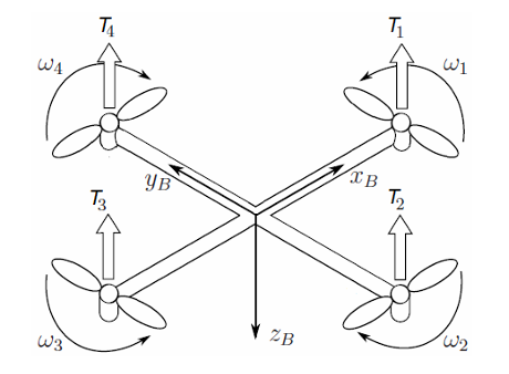
Figure 1. Force analysis of a quadrotor UAV [5]
In a balanced state, the quadrotor employs a specific rotation strategy for its rotors to maintain stability and control. Rotors 1 and 3 rotate in a counterclockwise direction, whereas rotors 2 and 4 rotate clockwise. This arrangement is critical for counteracting the gyroscopic and aerodynamic torque effects produced by the motors at high speeds, which, if unmanaged, would cause the vehicle to spin uncontrollably [6]. The quadrotor can move in six degrees of freedom within space, encompassing both translational and rotational movements along three axes. However, for the purposes of this analysis, the focus will be on the control of pitch, roll, and yaw movements.
Control over the pitch of the UAV is achieved by varying the rotational speeds of rotors 1 and 3 while keeping the speeds of rotors 2 and 4 constant. This adjustment generates a torque that influences the UAV to pitch forward or backward. Conversely, to initiate a roll motion, the rotational speeds of rotors 2 and 4 are altered while maintaining constant speeds for rotors 1 and 3. This change in speed induces a torque that causes the UAV to roll to the side. Lastly, to control yaw movement, the rotational speeds of both pair of rotors (1 and 3 or 2 and 4) are varied simultaneously while ensuring the total lift force counterbalances the force of gravity. This manipulation of speeds creates an anti-torque effect, allowing the UAV to rotate around its vertical axis without altering its position in space.
These methods of manipulating the rotational speeds of the rotors to control pitch, roll, and yaw movements are fundamental to the quadrotor's ability to navigate and maneuver through its environment. By carefully adjusting these speeds, the UAV can achieve precise movements and maintain stability during flight.
It follows that the rotational moments for which these three motions can be realized are shown in formula 1.
\( [ \begin{array}{c} F \\ {M_{x}} \\ {M_{y}} \\ {M_{z}} \end{array} ]=[ \begin{array}{c} {u_{1}} \\ {u_{2}} \\ {u_{3}} \\ {u_{4}} \end{array} ]=[ \begin{array}{c} {k_{F}}\sum _{i=1}^{4}{{ω_{i}}^{2}} \\ {k_{F}}l({{ω_{4}}^{2}}-{{ ω_{2}}^{2}}) \\ {k_{F}}l({{ω_{3}}^{2}}- {{ω_{1}}^{2}}) \\ {k_{M}}({{ω_{1}}^{2}}+{{ω_{3}}^{2}}- {{ω_{4}}^{2}}-{{ ω_{2}}^{2}}) \end{array} ] \) (1)
Where \( F \) means Lift for vertical motion of the vehicle, and \( {M_{x}} , {M_{y}} \) , \( {M_{z}} \) represent the rotational moments for quadrotor pitch, roll and yaw motions. \( {k_{F}} \) represents lift coefficient, and \( {k_{M}} \) is rotational moment coefficient.
2.1.2. Dynamic model
To accurately represent the vehicle's attitude and movement, the establishment of vector coordinate systems is essential. These include the Earth coordinate system, denoted as e (x, y, z), and the vehicle's body coordinate system, labeled b (x, y, z). The Earth coordinate system's origin is situated at the Earth's center, while the body coordinate system's origin aligns with the vehicle's center. For computational convenience, aligning the origins of these coordinate systems is required. This alignment involves rotating the Earth coordinate system about the x, y, and z axes, following the sequence z, y, x, to derive the rotation matrix that transitions from the Earth to the body coordinate system [7].
\( R=[\begin{matrix}cosθcosψ & sinϕsinθcosψ - cosϕsinψ & cosϕsinθcosψ+sinϕsinψ \\ cosθsinψ & sinϕsinθsinψ+cosϕcosψ & cosϕsinθsinψ- sinϕcosψ \\ -sinθ & sinϕcosθ & cosϕcosθ \\ \end{matrix}] \) (2)
The rotation matrix is a vital component of quadrotor dynamics as it transforms vectors from the body coordinate system to the earth coordinate system. This transformation is necessary to accurately represent the quadrotor's position and speed within the Earth's coordinate framework. It significantly aids the flight controller in determining the vehicle's precise location and velocity. Representing the tensile forces and moments acting on the quadrotor, as well as sensor measurements, is more intuitive when done in the airframe coordinate system. The rotation matrix simplifies the complexity of navigating and controlling the quadrotor in three-dimensional space, enabling more effective and intuitive flight management. This representation duality improves the understanding and control of the quadrotor's flight dynamics, enhancing its stability and performance in the air [3].
In the Earth coordinate system, linear positions are represented by \( ξ={[x,y,z]^{T}} \) , linear velocities are represented by \( {V_{e}}={[\dot{x}, \dot{y}, \dot{z}]^{T}}, \) angular positions are represented by \( η={[θ,ψ,ϕ]^{T}} \) with pitch angle \( θ \) , roll angle \( ϕ \) , yaw angle \( ψ \) . And angular speed is defined by \( \dot{η}={[\dot{θ}, \dot{ψ}, \dot{ϕ}]^{T}} \) .
In body coordinate system, linear velocities are defined as \( {V_{b}}={[u,v,ω]^{T}}, \) and angular velocities is defined as \( ϑ={[p, q, r]^{T}} \) . But since angular velocity is a vector pointing towards the axis of rotation and \( \dot{η} \) is just the time derivative of \( η \) , the equation is needed:
\( ϑ={R_{r}}\dot{η} \) which means \( \dot{η}= {{R_{r}}^{-1}}ϑ \) (3)
Where \( {R_{r}} \) transformation matrix is given as:
\( {R_{r}}=[\begin{matrix}1 & 0 & -sinθ \\ 0 & cosϕ & sinϕcosθ \\ 0 & -sinϕ & cosϕcosθ \\ \end{matrix}] \) (4)
Since the pitch and roll angles are small due to neglecting air resistance, we approximate the \( sin{θ}≈ sin{ϕ} ≈0 \) , \( cos{θ}≈cos{ϕ}≈1 \) .
the relationship between \( ϑ \) and \( \dot{η} \) can be reduced to:
\( {[p, q, r]^{T}} \) = \( {[\dot{θ}, \dot{ψ}, \dot{ϕ}]^{T}} \) (5)
Since in body coordination system \( {F_{b}}={[0 0 {u_{1}}]^{T}} \) , \( {G_{e}}={[0 0 mg]^{T}} \) , then get:
\( {F_{e}}= R{F_{b}}={u_{1}}[ \begin{array}{c} sinϕsinψ+cosϕcosψsinθ \\ -cosψsinϕ+cosϕsinψsinθ \\ cosϕcosθ \end{array} ] \) (6)
From Newton's second law:
\( \ddot{x}=\frac{sinϕsinψ+cosϕcosψsinθ}{m}{u_{1}} \) (7)
\( \ddot{y}=\frac{-cosψsinϕ+cosϕsinψsinθ}{m}{u_{1}} \) (8)
\( \ddot{z}= \frac{cosϕcosθ}{m}-g \) (9)
Newton's Euler equations are known as:
\( I\dot{ϑ} + ϑ×(Iϑ) = τ \) (10)
Where \( ϑ= {[p, q, r]^{T}}, τ={[{u_{2}}, {u_{3}} ,{u_{4}}]^{T}}, I= [\begin{matrix}{I_{xx}} & 0 & 0 \\ 0 & {I_{yy}} & 0 \\ 0 & 0 & {I_{zz}} \\ \end{matrix}] \)
Due to smaller angular velocity vectors during low-speed flights, \( ϑ×(Iϑ) \) can be consider as 0 [8]. Then get:
\( [\begin{matrix}{I_{xx}} & 0 & 0 \\ 0 & {I_{yy}} & 0 \\ 0 & 0 & {I_{zz}} \\ \end{matrix}][ \begin{array}{c} \dot{p} \\ \dot{q} \\ \dot{r} \end{array} ] \) = \( [ \begin{array}{c} {u_{2}} \\ {u_{3}} \\ {u_{4}} \end{array} ] \) (11)
\( [ \begin{array}{c} \dot{p} \\ \dot{q} \\ \dot{r} \end{array} ] = [ \begin{array}{c} \ddot{ϕ} \\ \ddot{θ} \\ \ddot{ψ} \end{array} ]=[ \begin{array}{c} {u_{2}}/{I_{xx}} \\ {u_{3}}/{I_{yy}} \\ {u_{4}}/{I_{zz}} \end{array} ] \) (12)
Finally, nonlinear dynamical model is as in formula 13 [9].
\( d=[ \begin{array}{c} \ddot{x} \\ \ddot{y} \\ \ddot{z} \\ \ddot{ϕ} \\ \ddot{θ} \\ \ddot{ψ} \end{array} ]=[ \begin{array}{c} \frac{sinϕsinψ+cosϕcosψsinθ}{m}{u_{1}} \\ \frac{-cosψsinϕ+cosϕsinψsinθ}{m}{u_{1}} \\ \frac{cosϕcosθ}{m}-g \\ {u_{2}}/{I_{xx}} \\ {u_{3}}/{I_{yy}} \\ {u_{4}}/{I_{zz}} \end{array} ] \) (13)
2.2. Simulation
Parameters of the quadrotor model were obtained from the literature is shown in table 1 [10].
Table 1. Parameters of the quadrotor model
Parameters | Values |
\( {I_{xx}} \) | \( 2.353×{10^{-3}} kg∙{m^{2}} \) |
\( {I_{yy}} \) | \( 2.353×{10^{-3}} kg∙{m^{2}} \) |
\( {I_{zz}} \) | \( 3.262×{10^{-3}} kg∙{m^{2}} \) |
\( M \) | \( 1.2kg \) |
\( G \) | \( 9.8 m/{s^{2}} \) |
\( L \) | \( 0.2m \) |
The model was solved using the LPV method, assume that the system state equation is shown in formula 14 [11].
\( \begin{cases} \begin{array}{c} \dot{X}=AX+BU \\ Y=CX+DU \end{array} \end{cases} \) (14)
Where A is coefficient matrix, \( X={(\dot{x}, \dot{y}, \dot{z}, x, y,z,\dot{ϕ}, \dot{θ},\dot{ψ},ϕ,θ,ψ,g)^{T}} \) , B is input matrix, \( U={({U_{1}},{U_{2}},{U_{3}},{U_{4}})^{T}} \) , \( Y={(z,ϕ,θ,ψ)^{T}} \) , C is output matrix, and D is direct transfer matrix. The Laplace transform of the above equation yields the transfer function:
\( {G_{s}}=\frac{Y(s)}{U(s)}=C{(SI-A)^{-1}}B+D \) (15)
Then get:
\( {G_{1}}(s)=[\begin{matrix}\frac{0.8333}{{s^{2}}} & 0 & 0 & 0 \\ 0 & \frac{424.9894}{{s^{2}}} & 0 & 0 \\ 0 & 0 & \frac{424.9894}{{s^{2}}} & 0 \\ 0 & 0 & 0 & \frac{306.5604}{{s^{2}}} \\ \end{matrix}] \) (16)
The final linear model of the system needs to consider the first-order inertia model when ultimately used with a DC motor with a motor governor that generates lift in relation to the screw [12].
\( G(s)=\frac{d}{0.1s+1} \) (17)
This experiment is obtained by taking d to be 1 since d has a small effect, then get:
\( {G_{2}}(s)=[\begin{matrix}\frac{1}{0.1s+1} & 0 & 0 & 0 \\ 0 & \frac{1}{0.1s+1} & 0 & 0 \\ 0 & 0 & \frac{1}{0.1s+1} & 0 \\ 0 & 0 & 0 & \frac{1}{0.1s+1} \\ \end{matrix}] \) (18)
The final transfer function:
\( G(s)={G_{2}}(s) {G_{1}}(s)= [\begin{matrix}\frac{0.8333}{{0.1{s^{3}}+s^{2}}} & 0 & 0 & 0 \\ 0 & \frac{424.9894}{{0.1{s^{3}}+s^{2}}} & 0 & 0 \\ 0 & 0 & \frac{424.9894}{{0.1{s^{3}}+s^{2}}} & 0 \\ 0 & 0 & 0 & \frac{306.5604}{{0.1{s^{3}}+s^{2}}} \\ \end{matrix}] \) (19)
So, the transfer functions for pitch, roll and yaw can be obtained as:
\( {G_{θ}}=\frac{0.8333}{{0.1{s^{3}}+s^{2}}} \) (20)
\( {G_{ϕ}}=\frac{424.9894}{{0.1{s^{3}}+s^{2}}} \) (21)
\( {G_{ψ}}=\frac{306.5604}{{0.1{s^{3}}+s^{2}}} \) (22)
2.3. Results analysis
PID algorithms are based on a feedback law designed to control deviation and do not rely on the specific mathematical model of the controlled object. They have demonstrated good performance in many process control scenarios. Despite the emergence of various new control algorithms, the dominant position of PID control algorithms in industrial control has not been challenged. Figure 2 shows the PID controller designed in this study for the quadrotor to receive commands during flight.
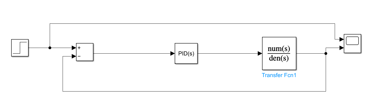
Figure 2. Simulation structure diagram (Photo/Picture credit: Original)
Build the simulation model of each control channel in MATLAB to get its disturbance curve shown as figure 3-5.
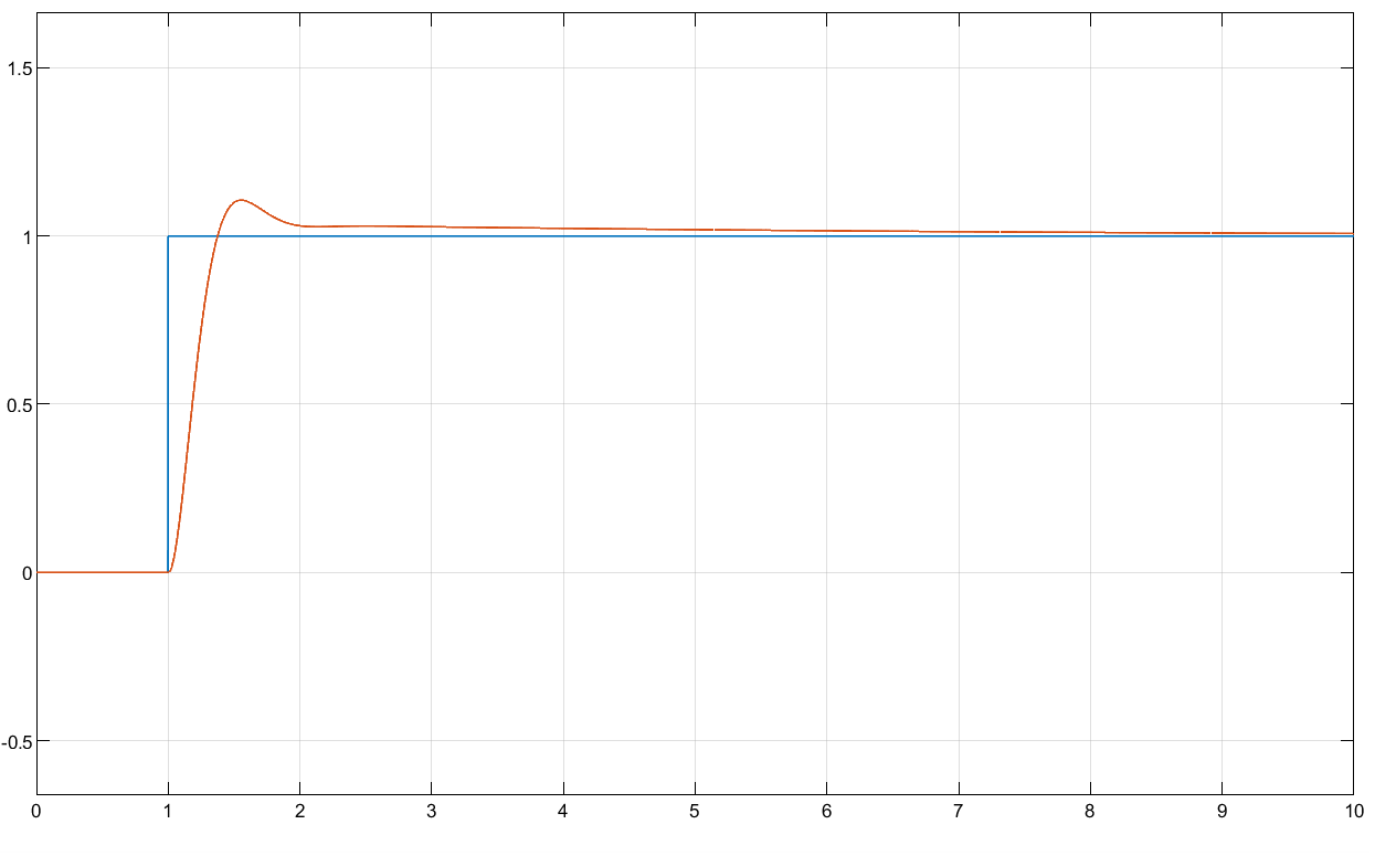
Figure 3. Pitch (Photo/Picture credit: Original)
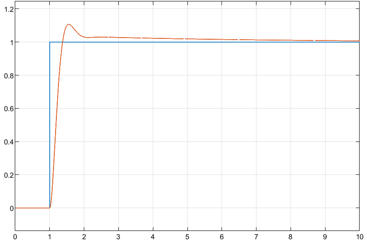
Figure 4. Roll (Photo/Picture credit: Original)
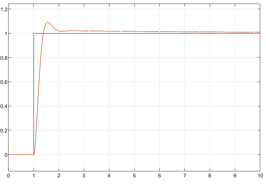
Figure 5. Yaw (Photo/Picture credit: Original)
Figures 3-5 demonstrate that all channels exhibit excellent control performance. The system responds quickly, reaching a steady state in approximately 1.0s, with minimal overshoot and no steady-state error. This indicates that the PID control system is effective in controlling the quadrotor, allowing the vehicle to follow the designated trajectory even in the presence of disturbances. This demonstrates that the designed PID controller possesses anti-interference capabilities, ensuring the robustness and reliability of the control system in practical applications.
3. Application scenarios
In Walid, Missouri’s paper, it presents a comprehensive approach to modelling and controlling a quadrotor UAV, with emphasis on the vehicle's dynamics and control strategies [13]. The Lagrange formalism is used to develop a mathematical model. A significant portion of the document is dedicated to the control strategy, with particular focus on a Proportional-Derivative (PD) control approach. The aim of this strategy is to stabilize the quadrotor's position and attitude by adjusting the PD controller gains and analyzing their effects on system responses. The control system is divided into two subsystems for managing positions and angles. Specific equations are provided for vertical and horizontal position control, as well as attitude control. Additionally, the document explains the implementation of a converter block that calculates appropriate angular speeds from controller outputs, enabling the quadrotor to maintain stability and maneuverability. This has been validated through simulations using MATLAB/Simulink.
Li Zhang establishes a mathematical model for the quadrotor UAV based on physics and mechanics theory and designs the hardware circuit part of the control system, which provides hardware support for the implementation of the quadrotor UAV control algorithm [14]. Then, the flight control system of the quadrotor UAV is designed based on the serial PID control algorithm, and the control system is verified to have strong stability and anti-interference ability through simulation flight experiments.
Najm analyses the stability conditions of the system by constructing a mathematical model of the system and uses these conditions to design a nonlinear PID controller [15]. The objective of the controller design is to ensure the stability and controllability of the UAV under various flight conditions, considering the nonlinear characteristics and possible external disturbances in the system. The stability conditions mentioned in the paper are given through the Hurwitz stability criterion and these conditions ensure the closed-loop stability of the system. To validate the effectiveness of the designed controller, the paper presents a series of simulation results and case studies. These simulations consider different flight missions and external disturbances and demonstrate the effectiveness and robustness of the quadrotor UAV under the action of the PID controller under different flight conditions.
Haijun He’s thesis is devoted to the research of attitude stabilization and trajectory tracking control problem of quadrotor vehicle, and a novel attitude trajectory tracking control method is proposed [16]. The thesis firstly establishes the dynamics model of the quadrotor vehicle based on Newton's second law and Euler's equation. On this basis, a control system with a double-closed-loop structure is designed, in which the outer-loop position controller is designed by a novel inversion method, which is simple in structure and easy to be implemented in engineering; and the inner-loop attitude controller adopts a new type of self-resistant controller constructed by hyperbolic tangent function. This controller can accurately compensate the internal and external perturbations of the system estimated by the state observer by redesigning the nonlinear state error feedback control rate, effectively overcoming the serious coupling problem between the outer-loop position and the inner-loop attitude, and thus enabling the system state to converge globally and rapidly. The simulation results show that the control system can quickly track the desired attitude and trajectory with fast response, high stability accuracy, good stability and small overshooting amount, which realizes the effective flight of the quadrotor.
4. Conclusion
In conclusion, this study successfully verifies the effectiveness of the PID control strategy in improving the stability and control performance of a quadrotor UAV by establishing a quadrotor UAV model based on PID control and performing detailed simulation analysis. The flight performance of the UAV is improved by adjusting the PID parameters. By adjusting the PID parameters, the flight performance of the UAV was optimized, including the improvement of its response speed, stability and trajectory tracking accuracy. The successful implementation of this study provides an important theoretical foundation and practical guidance for the control system design and performance optimization of future quadrotor UAVs.
However, the widespread adoption of quadcopter UAVs introduces challenges such as ensuring flight safety to prevent airborne collisions, protecting personal privacy, and overcoming technological limitations related to load capacity, flight velocity, and stability. Additionally, increasing concerns over electronic jamming and cyber-attacks necessitate enhanced anti-jamming capabilities and cybersecurity measures.
Looking ahead, the integration of cutting-edge technologies like artificial intelligence, machine learning, computer vision, and sensing technologies promises to make quadcopter UAVs more intelligent, capable of autonomous navigation, obstacle avoidance, and decision-making. Advancements in energy utilization, including solar and fuel cell technologies, aim to significantly extend UAV endurance. Furthermore, progress in communication technologies, particularly 5G and the forthcoming 6G, will enable longer-distance and more reliable connections, facilitating real-time data exchange and remote control. As quadcopter drones find broader applications in fields such as agriculture, rescue operations, logistics, and distribution, the development of sophisticated management systems will be crucial to ensure their safe and efficient operation.
References
[1]. Zhou Hui, & Song Yi. (2016). Design and simulation of attitude control for quadrotor based on Matlab. Science & Technology Information, 14(20), 62-62.
[2]. Chen Tingyu. (2018). Quadrotor modeling, simulation and PID control. Electronics World, (21), 5-7.
[3]. Amin, R., Li, A., & Shamshirband, S. (2016). A review of quadrotor UAV: control methodologies and performance evaluation. International Journal of Automation and Control, 10(2), 87-103.
[4]. Bouabdallah, S. (2007). Design and control of quadrotors with application to autonomous flying. Thesis, EPFL.
[5]. Cárdenas, J. A., et al. (2022). Optimal PID ø axis control for UAV quadrotor based on multi-objective PSO. IFAC-PapersOnLine, 55(14), 101-106.
[6]. Abbas, N. H., & Sami, A. R. (2017). Tuning of PID controllers for quadcopter system using hybrid memory based gravitational search algorithm–particle swarm optimization. International Journal of Computer Applications, 172(04), 9-18.
[7]. Khusheef, A. S. (2016). An efficient approach for modeling and control of a quadrotor. Wasit Journal of Engineering Sciences, 4(2), 1-16.
[8]. Zhang, P. (2019). Modeling and simulation of attitude control of quadrotor aircraft. Electric Machine Control Application, 46, 70-74.
[9]. Dong, W., et al. (2013). Modeling and control of a quadrotor UAV with aerodynamic concepts. World Academy of Science, Engineering and Technology, 7(5), 901-906.
[10]. Li Jun, & Li Yuntang. (2012). Dynamics modeling and PID control of quadrotor. Journal of Liaoning Technical University (Natural Science), 31(1), 114-117.
[11]. Zhao Yongliang, Zhou Chaoying, & Xie Peng. (2015). Dynamics modeling and control system design for multi-rotor aircraft. Mechanical and Electrical Product Development and Innovation, 4, 102-104.
[12]. Jiang Jie, & Qi Weinan. (2013). Modeling and PID controller design for quadrotor. Electronic Design Engineering, 21(23), 147-150.
[13]. Walid, M., et al. (2014). Modeling and control of a quadrotor UAV. Proceedings of the 2014 15th International Conference on Sciences and Techniques of Automatic Control and Computer Engineering (STA). IEEE.
[14]. Zhang Li. (2023). Design of quadrotor UAV control system based on cascaded PID control algorithm. Information Technology and Informatization, (01), 100-103.
[15]. Najm, A. A., & Ibraheem, I. K. (2019). Nonlinear PID controller design for a 6-DOF UAV quadrotor system. Engineering Science and Technology, an International Journal, 22(4), 1087-1097.
[16]. He Haijun, et al. (2018). Simulation study on attitude trajectory tracking control of quadrotor aircraft. Computer Simulation, 35(6), 37-41.
Cite this article
Liu,Y. (2024). Modelling and simulation of quadcopter UAV based on PID control. Applied and Computational Engineering,75,202-210.
Data availability
The datasets used and/or analyzed during the current study will be available from the authors upon reasonable request.
Disclaimer/Publisher's Note
The statements, opinions and data contained in all publications are solely those of the individual author(s) and contributor(s) and not of EWA Publishing and/or the editor(s). EWA Publishing and/or the editor(s) disclaim responsibility for any injury to people or property resulting from any ideas, methods, instructions or products referred to in the content.
About volume
Volume title: Proceedings of the 2nd International Conference on Software Engineering and Machine Learning
© 2024 by the author(s). Licensee EWA Publishing, Oxford, UK. This article is an open access article distributed under the terms and
conditions of the Creative Commons Attribution (CC BY) license. Authors who
publish this series agree to the following terms:
1. Authors retain copyright and grant the series right of first publication with the work simultaneously licensed under a Creative Commons
Attribution License that allows others to share the work with an acknowledgment of the work's authorship and initial publication in this
series.
2. Authors are able to enter into separate, additional contractual arrangements for the non-exclusive distribution of the series's published
version of the work (e.g., post it to an institutional repository or publish it in a book), with an acknowledgment of its initial
publication in this series.
3. Authors are permitted and encouraged to post their work online (e.g., in institutional repositories or on their website) prior to and
during the submission process, as it can lead to productive exchanges, as well as earlier and greater citation of published work (See
Open access policy for details).
References
[1]. Zhou Hui, & Song Yi. (2016). Design and simulation of attitude control for quadrotor based on Matlab. Science & Technology Information, 14(20), 62-62.
[2]. Chen Tingyu. (2018). Quadrotor modeling, simulation and PID control. Electronics World, (21), 5-7.
[3]. Amin, R., Li, A., & Shamshirband, S. (2016). A review of quadrotor UAV: control methodologies and performance evaluation. International Journal of Automation and Control, 10(2), 87-103.
[4]. Bouabdallah, S. (2007). Design and control of quadrotors with application to autonomous flying. Thesis, EPFL.
[5]. Cárdenas, J. A., et al. (2022). Optimal PID ø axis control for UAV quadrotor based on multi-objective PSO. IFAC-PapersOnLine, 55(14), 101-106.
[6]. Abbas, N. H., & Sami, A. R. (2017). Tuning of PID controllers for quadcopter system using hybrid memory based gravitational search algorithm–particle swarm optimization. International Journal of Computer Applications, 172(04), 9-18.
[7]. Khusheef, A. S. (2016). An efficient approach for modeling and control of a quadrotor. Wasit Journal of Engineering Sciences, 4(2), 1-16.
[8]. Zhang, P. (2019). Modeling and simulation of attitude control of quadrotor aircraft. Electric Machine Control Application, 46, 70-74.
[9]. Dong, W., et al. (2013). Modeling and control of a quadrotor UAV with aerodynamic concepts. World Academy of Science, Engineering and Technology, 7(5), 901-906.
[10]. Li Jun, & Li Yuntang. (2012). Dynamics modeling and PID control of quadrotor. Journal of Liaoning Technical University (Natural Science), 31(1), 114-117.
[11]. Zhao Yongliang, Zhou Chaoying, & Xie Peng. (2015). Dynamics modeling and control system design for multi-rotor aircraft. Mechanical and Electrical Product Development and Innovation, 4, 102-104.
[12]. Jiang Jie, & Qi Weinan. (2013). Modeling and PID controller design for quadrotor. Electronic Design Engineering, 21(23), 147-150.
[13]. Walid, M., et al. (2014). Modeling and control of a quadrotor UAV. Proceedings of the 2014 15th International Conference on Sciences and Techniques of Automatic Control and Computer Engineering (STA). IEEE.
[14]. Zhang Li. (2023). Design of quadrotor UAV control system based on cascaded PID control algorithm. Information Technology and Informatization, (01), 100-103.
[15]. Najm, A. A., & Ibraheem, I. K. (2019). Nonlinear PID controller design for a 6-DOF UAV quadrotor system. Engineering Science and Technology, an International Journal, 22(4), 1087-1097.
[16]. He Haijun, et al. (2018). Simulation study on attitude trajectory tracking control of quadrotor aircraft. Computer Simulation, 35(6), 37-41.