


1. Introduction
Six degrees of freedom is also known as 6-DOF, and the robotic arm model we will talk about today is all about flipping. There is a joint between each material that can be flipped. There are three types of flips: tilt, roll, and twist. The robotic arm is programmable and can command and execute various functions like a human arm. Although the 6-DOF robotic arm cannot be translated, it can be applied to factories and hospitals by the flexibility between each part.
In industrial production, robotic arms help workers stay safe by operating in dangerous environments and performing tasks that carry a high risk of injury to humans and reduce labor costs [1]. Mostly AMRS, AGVs, articulated robots and co-robots to help speed up processes, increase efficiency and improve safety. The robot arm can also complete welding, installation and pasting.
In healthcare systems, robotic arms are controlled remotely to perform surgery or treatment, allowing providers to focus on reaching and caring for patients. For example, AMRS delivers medicine, disinfects surfaces, or provides mobile remote sensing functions. Suppose the attending doctor cannot arrive at the hospital in time for special reasons. In that case, the treatment can be completed by controlling the robotic arm from a distance, ensuring no accidents and the patient is treated in time [2].
The following are the major contributions of our work on the development of robotic manipulators.
1) Revolute joints make the end-effector can reach many points. The revolute joint at the end ensures that the end-effector can flexibly respond to space constraints and get the operating position from different directions.
2) The joints are all revolute joints, making it easy to model and select mates in SolidWorks.
3) 6-DOF manipulators are very common in industrial production. Different end sensors can be used in some innovative areas.
The following is the Organization of this work.
We organize the remaining article as follows. Section II displays the modeling inspirations from other articles. Section III shows the details of modeling, its Simulink results and finite element analysis. Section IV presents the application of two kinds of 6-DOF robotic manipulators with different end effectors. Section V explains the problems in modelling the robotic manipulator, their possible influences, and the parts to be optimized, such as adding a controller.
2. Related Work
This section reviews the mechanical design and FEA analysis of the robotic arm, which also contains some improvements to the CAD model.
To better understand the robotic arm’s structure and the revolute joint’s operation principle, modelling and simulation of the 6-DOF robot arm widely used in industrial production was a suitable research method. The modelling was based on the design of the robotic arm in two references. Design and fabrication of six axial arm robots [3] The robotic arm represented one degree of freedom by a grip-and-release action of the end effector. Structural design and simulation of 6-DOF robot based on genetic algorithm [4] The robotic arm was equipped with a spherical wrist rather than a revolute joint with only one degree of freedom. Based on those mentioned above, this study aimed to understand the operation principle of revolute joints. Then, the robot arm should have six rotating joints, and the spherical wrist was not allowed to appear in this model. At the same time, the model was not equipped with an end effector that could grab and drop but let the entire end effector rotate. After modification, a robotic arm model with 6-DOF and six revolute joints was born.
3. Mechanical Design and Simulation
3.1. Design
The manipulator was modeled with a base and six links, each connected by a rotating joint, resulting in an open kinematic chain of 6-DOF. The types of mates used in this model were coincidence, coaxial, and angle limitation. The 6-DOF robotic arm is similar to the human arm, and the six movements it can achieve are bottom joint rotation, lower arm swing, upper arm swing, wrist rotation, wrist swing, and end effector rotation.
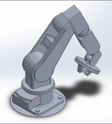
Figure 1. The CAD model of the Robotic Arm.
3.2. Simulink
We import the CAD model of the 6-DOF robot arm into Simulink to coordinate transformation. This model is mainly built up of two parts: basic objects and the data processing model.
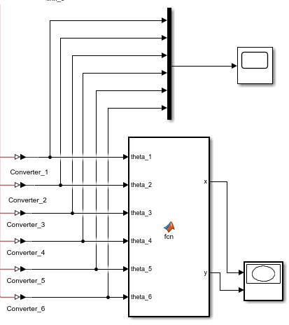
Figure 2. Data Collection and Analysis
By Setting the appropriate torque and angle limit for each joint so that the manipulator can swing. This model has a torque of 1N*m for all joints except joint_2 with 0.5N*m. The different setting of joint_2 is because the length of link_3 connected to it is long. The module will shake too severely if the torque set is too large.
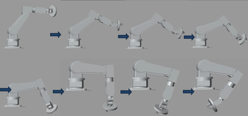
Figure 3. Operation Process of Mechanical Arm
The XY plot presents the motion trajectory of the end of the robotic arm, which a position function and the length of each link can calculate. The marks on the XY plot of 0.1s are consistent with the swing of the mechanical arm shown in Fig. 3. Extend the time to 2.5s so that the end effector is moving almost the same.
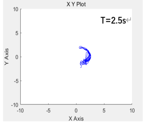
Figure 4. The Motion Trajectory of The End of The Robotic Arm
3.3. C. FEA
To verify whether the structure of this robot arm was reasonable, the model should undergo several static simulations. A block is fixed on the end effector, and a vertical downward force is applied on the lower surface of the block to simulate the load-bearing situation. In several experiments, the easily yielding parts of the model were thickened to allow greater weight to be borne. The upper arm was low, and the wrist was straightforward to simulate picking up the goods. The upper arm was raised, and the wrist was lowered to simulate lifting the goods. After repeatedly modifying the force magnitudes and running them, the maximum force the model can withstand under two situations was 5N and 15N, respectively. The interface of small elements near the end is very prone to yield.
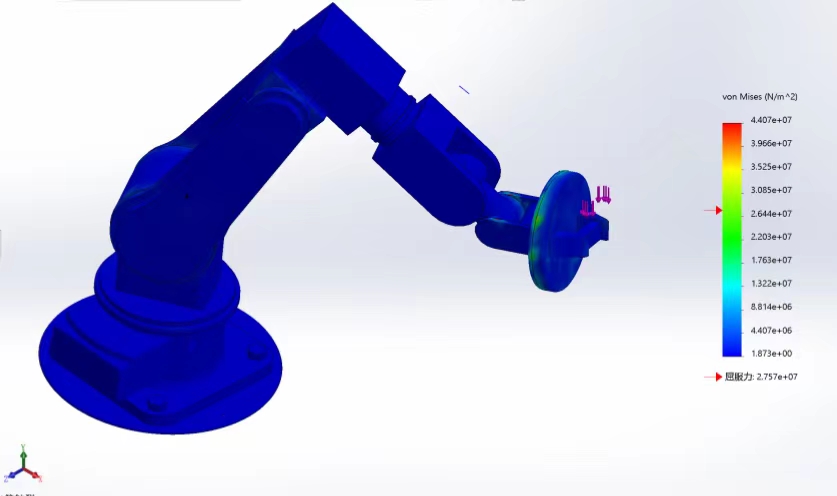
Figure 5. FEA of the Robotic Arm with 5N Payload On the End-effector.
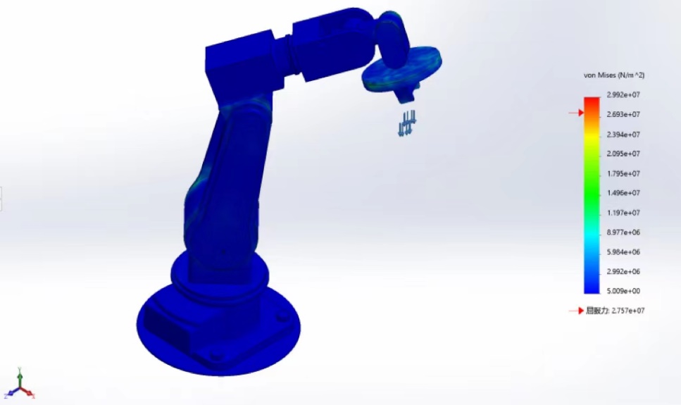
Figure 6. FEA of the Robotic Arm with 15N Payload On the End-effector.
4. Applications
The manipulator can be seen everywhere because of its high accuracy. It is mainly used instead of manual labor or time-consuming work. The accuracy and durability of robotic arms can reduce the unpredictability of human problems. Some factories have also introduced robots to improve factory output; robot efficiency is much higher than human, and high precision.
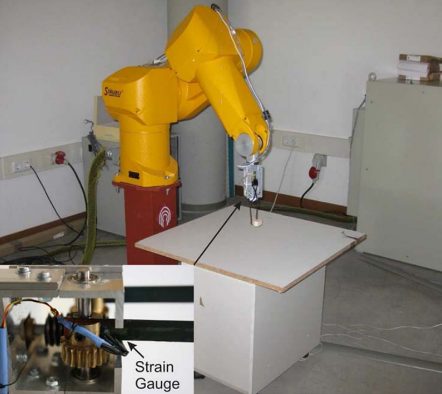
Figure 7. Experimental setup and details of the gripper mechanisms and sensor [5].
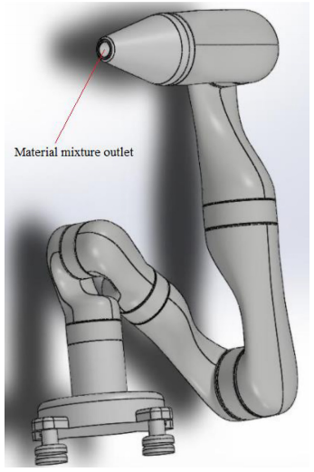
Figure 8. A small-scale robot manipulator design for construction engineering [6].
Fig. 7. shows a 6-DOF manipulator for grasping objects. Based on the soft properties of the materials, the flexible 6-DOF manipulator can absorb energy during collisions and perform well in holding objects [5].
Fig. 8. shows a 3D printing 6-DOF manipulator. It can discharge materials for the construction of buildings [6].
Although the end effector is not designed to be a grip that can grasp and place items substantially, the gripper rotating around the shaft can open and close the lid with a larger diameter. Some raw materials are stored in barrels in industrial production, and the lid’s diameter is more significant. Unlike beverage caps, large-diameter caps cannot be closed by human fingers and wrists alone, requiring more energy. If the raw materials in the barrel have high sealing requirements, such as solid volatility, it is more necessary to tighten the lid firmly. Nowadays, the shopping mall entertainment handmade experience museum rises. This experience center allows customers to experience wood carving and silver jewelry making. A robot arm with a sculpting function can be obtained if the end sensor and its connected parts with the component are replaced. In the new design, the end effector is a rigid body shaped like a pencil, which rotates itself to achieve the engraving function. Customers can design complex patterns and carve them into a rigid material with a robotic arm. The engraving function provides more possibilities for manufacturing items, thus realizing its economic value. The new design has 6-DOF, and each joint is a revolute joint, which is consistent with the purpose of this study.
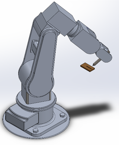
Figure 9. The robot arm with a sculpting function
5. Conclusion
In this paper, the modelling, simulation, and finite element analysis are completed, and thinking about innovative application scenarios. The FEA and Simulink are demonstrated as being the most crucial components. It is clear how the robotic arm is made and functions. This report can provide inspiration and suggestions for future students working on this project. Future work can be extended to the experimental platform of an accurate robotic arm.
The Six-DOF robotic Manipulator simulation and FEA in this study are developed based on the CAD model and are proven to work well. If there is an extra opportunity to do the project again. First, the structures will be considered. A new model and materials will be researched to make the model more stable and flexible. Second, a trajectory controller will be added. Inaccurate modelling and inaccurate system parameters cause system disturbance.
References
[1]. N. S. Krishnaraj Rao et al., “An automated robotic arm: A machine learning approach,” 2021 IEEE International Conference on Mobile Networks and Wireless Communications (ICMNWC), 2021. doi:10.1109/icmnwc52512.2021.9688512
[2]. A. Okamura, M. Mataric, and C. Henrik, “Medical and healthcare robotics,” IEEE Robotics & Automation Magazine - IEEE ROBOT AUTOMAT, vol. 17, pp. 26–37, 2010. doi:10.1016/c2022-0-00158-6
[3]. K. N. Gunasekaran, C. Vasu, V. Ram N S, R. G. Tharun Athi, and R. S. Vijayamoorthi, “Design and fabrication of six axial arm robot,” IOP Conference Series: Materials Science and Engineering, vol. 1132, no. 1, p. 012004, 2021. doi:10.1088/1757-899x/1132/1/012004
[4]. H. Li and A. Yan, “Structural design and simulation of 6-DOF robot based on genetic algorithm,” 2021 2nd International Conference on Artificial Intelligence and Information Systems, 2021. doi:10.1145/3469213.3471382
[5]. J. Becedas, I. Payo, and V. Feliu, “Two-Flexible-Fingers Gripper Force Feedback Control System for Its Application as End Effector on a 6-DOF Manipulator,” IEEE Transactions on Robotics, vol. 27, no. 3, pp. 599–615, 2011. doi:10.1109/tro.2011.2132850
[6]. Md. H. Ali, Y. Kuralbay, A. Aitmaganbet, and M. A. S. Kamal, “Design of a 6-DOF robot manipulator for 3D printed construction,” Materials Today: Proceedings, vol. 49, pp. 1462–1468, 2022. doi:10.1016/j.matpr.2021.07.228
Cite this article
He,R.;Wang,Y.;Li,T. (2024). Design and control of the Six-DOF robotic manipulator. Applied and Computational Engineering,78,129-135.
Data availability
The datasets used and/or analyzed during the current study will be available from the authors upon reasonable request.
Disclaimer/Publisher's Note
The statements, opinions and data contained in all publications are solely those of the individual author(s) and contributor(s) and not of EWA Publishing and/or the editor(s). EWA Publishing and/or the editor(s) disclaim responsibility for any injury to people or property resulting from any ideas, methods, instructions or products referred to in the content.
About volume
Volume title: Proceedings of the 2nd International Conference on Mechatronics and Smart Systems
© 2024 by the author(s). Licensee EWA Publishing, Oxford, UK. This article is an open access article distributed under the terms and
conditions of the Creative Commons Attribution (CC BY) license. Authors who
publish this series agree to the following terms:
1. Authors retain copyright and grant the series right of first publication with the work simultaneously licensed under a Creative Commons
Attribution License that allows others to share the work with an acknowledgment of the work's authorship and initial publication in this
series.
2. Authors are able to enter into separate, additional contractual arrangements for the non-exclusive distribution of the series's published
version of the work (e.g., post it to an institutional repository or publish it in a book), with an acknowledgment of its initial
publication in this series.
3. Authors are permitted and encouraged to post their work online (e.g., in institutional repositories or on their website) prior to and
during the submission process, as it can lead to productive exchanges, as well as earlier and greater citation of published work (See
Open access policy for details).
References
[1]. N. S. Krishnaraj Rao et al., “An automated robotic arm: A machine learning approach,” 2021 IEEE International Conference on Mobile Networks and Wireless Communications (ICMNWC), 2021. doi:10.1109/icmnwc52512.2021.9688512
[2]. A. Okamura, M. Mataric, and C. Henrik, “Medical and healthcare robotics,” IEEE Robotics & Automation Magazine - IEEE ROBOT AUTOMAT, vol. 17, pp. 26–37, 2010. doi:10.1016/c2022-0-00158-6
[3]. K. N. Gunasekaran, C. Vasu, V. Ram N S, R. G. Tharun Athi, and R. S. Vijayamoorthi, “Design and fabrication of six axial arm robot,” IOP Conference Series: Materials Science and Engineering, vol. 1132, no. 1, p. 012004, 2021. doi:10.1088/1757-899x/1132/1/012004
[4]. H. Li and A. Yan, “Structural design and simulation of 6-DOF robot based on genetic algorithm,” 2021 2nd International Conference on Artificial Intelligence and Information Systems, 2021. doi:10.1145/3469213.3471382
[5]. J. Becedas, I. Payo, and V. Feliu, “Two-Flexible-Fingers Gripper Force Feedback Control System for Its Application as End Effector on a 6-DOF Manipulator,” IEEE Transactions on Robotics, vol. 27, no. 3, pp. 599–615, 2011. doi:10.1109/tro.2011.2132850
[6]. Md. H. Ali, Y. Kuralbay, A. Aitmaganbet, and M. A. S. Kamal, “Design of a 6-DOF robot manipulator for 3D printed construction,” Materials Today: Proceedings, vol. 49, pp. 1462–1468, 2022. doi:10.1016/j.matpr.2021.07.228