


1. Introduction
CO2 emissions have led to increasing global warming and the greenhouse effect, meanwhile, vehicles, as the mainstream means of transportation, are also one of the main sources of pollution. At this stage there is a need to reduce vehicle emissions and improve vehicle energy efficiency and energy recovery systems offer us a new strategy.
Kinetic energy recovery systems (KERS) are a form of regenerative system that has different approaches to store and reuse the lost energy during deceleration. In this paper, we studied two major types of KERS, regenerative braking system and flywheel energy storage system (FESS). Regenerative braking is harness motors or sensors capable of converting thermal energy into electricity, effectively capturing energy from the braking process. This captured energy can subsequently be employed to power the electric motor during acceleration or to supplement other vehicle functions. By recuperating and repurposing this energy, regenerative braking significantly enhances the overall energy efficiency of the vehicle, ultimately extending its driving range. The fundamental objective of this system is to achieve more efficient driving by reclaiming energy that would otherwise be wasted during braking, effectively transforming it into energy to propel the vehicle. Notably, under specific conditions, certain systems have demonstrated a remarkable regenerative braking energy recovery rate of up to 65.01% [1]. The FESS used in vehicles is connecting the flywheel with the driveline through a transmission that spins up the flywheel in the deceleration process, and vice versa, slows down when the vehicle is speeding up. This involves three separate stages during the process, which were further explain in the discussion part.
The thermal energy conversion and energy recovery of vehicles are divided into thermoelectric technology and Rankine cycle. The application of thermoelectric technology in automobiles is mainly reflected in the thermoelectric generator device, which contains thermoelectric material modules, radiators, thermal conductive plates, electronic components and other components. The Unileg thermoelectric generator (TGEs) [2] is the most representative, which is able to convert waste heat from exhaust gas into reusable electricity. Rankine cycle is a thermodynamic cycle system that converts heat into mechanical work, and the working fluid inside it powers a generator through a turbine to produce electrical or mechanical energy. Thermoelectric technology and Rankine cycle technology both improve energy efficiency by recovering lost heat.
Aside from thermoelectric technology, there is another technology that is closely related to energy conservation called ETC. Electric Turbo Compounding (E-TC) means installing a motor-generator unit on the exhaust side to recycle the energy of the exhaust to drive the turbine during start and stop periods. The energy in the exhaust gases can also be used to drive the fan blades of the turbine. The entire ETC can be divided into three different structures: sE-TC, pE-TC and eA-TC. These are three different layouts of the turbine and turbocharger. The specific structures are described below. ETC can effectively reduce CO2 emissions and improve fuel economy. When it comes to saving energy and protecting the environment, ETC is a very worthwhile method to consider. In this paper, it focus on one or some combination of ways to improve vehicle performance and make them more efficient and achieve some energy saving.
2. Discussion
This paper will review current literature on the energy recovery mechanisms of kinetic energy recovery system, heat energy by thermal energy conversion technology as well as Rankine cycle, and the potential of the transformation of electric turbine combination. These methods will be compared for their suitability as sustainable and efficient transportation systems.
2.1. Regenerative braking
In accordance with the research on the Control Strategy of Regenerative Braking Systems in Electric Vehicles [3], the focus of this study is on the implementation of strategies to optimize energy recovery during regenerative braking, thereby enhancing the energy efficiency and performance of braking in electric vehicles.
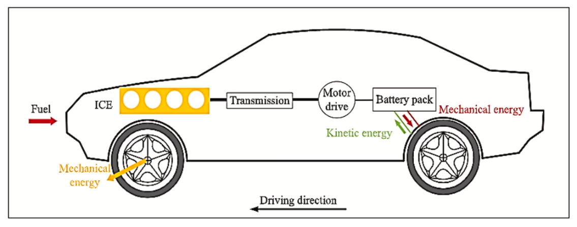
Figure 1. Schematic diagram representing energy flow of a hybrid electric vehicle employing an RBS[4]
The subtopic of this study addresses the inefficiency in energy utilization within electric vehicles, particularly in the context of braking. Traditional braking systems in electric vehicles result in dissipation of energy, thereby limiting the overall efficiency and range of the vehicle. To address this issue, He [5] proposes innovative strategies aimed at optimizing energy recovery during braking, thereby significantly enhancing the energy efficiency and overall performance of braking within electric vehicles. Central to regenerative braking systems is an electric machine (motor/generator) that either propels the vehicle or is propelled by the kinetic energy of the moving vehicle itself [6].
In essence, Atkins’s result [6] involves the development and implementation of strategies that optimize energy recovery not only during motor braking but also during electro-hydraulic compound braking in a dual-motor pure electric vehicle. This approach aims to minimize energy loss and enhance the overall efficiency of energy recovery, thereby improving braking performance for the vehicle. The methods employed to address the outlined problem are twofold: firstly, by refining torque distribution during regenerative braking to enhance energy recovery efficiency, and secondly, by introducing a dynamic control strategy for electro-hydraulic compound braking. This dynamic control strategy orchestrates the collaborative functioning of motor braking and hydraulic systems to reduce the disparity between target and actual braking torques. Simulation results corroborate the effectiveness of these strategies in augmenting energy recovery rates and improving the performance of the braking system.
In some vehicles, about 9% of the energy will be wasted through braking [7]. If the wasted energy in braking can be reused, the fuel consumption of cars will be reduced significantly as braking is used quite frequently. Inspiration is drawn from the electro-hydraulic composite braking system [5], which offers the flexibility to select from a range of braking modes to achieve the most economically efficient braking approach. The hydraulic braking mechanism incorporates a low-pressure reservoir, a hydraulic pump/motor, and high-pressure accumulators to store energy in compressed gas [6]. During braking, this energy is transformed into pressure within the working fluid. Subsequently, the expelled liquid, via a hydraulic motor, channels the power back into the transmission at a suitable location.
A hybrid system’s most important parameter is its energy storage capacity during braking. After doing experiments in single braking and dual braking mode, Fig 2. and Fig 3. shows the final result of the percent of the energy stored after the braking. Utilizing this strategy, experimental results indicate a 3.35% enhancement in energy recovery and an efficiency of 92% when compared to conventional average distribution control, which uses batteries to store the energy for future use and has only an efficiency of 82% [8]. Additionally, the coordination strategy reduces braking distance by up to 0.698%, thereby underscoring the efficacy of the proposed strategies in amplifying energy recovery and overall performance, thereby confirming the distinctiveness and effectiveness of these strategies when compared to conventional approaches.
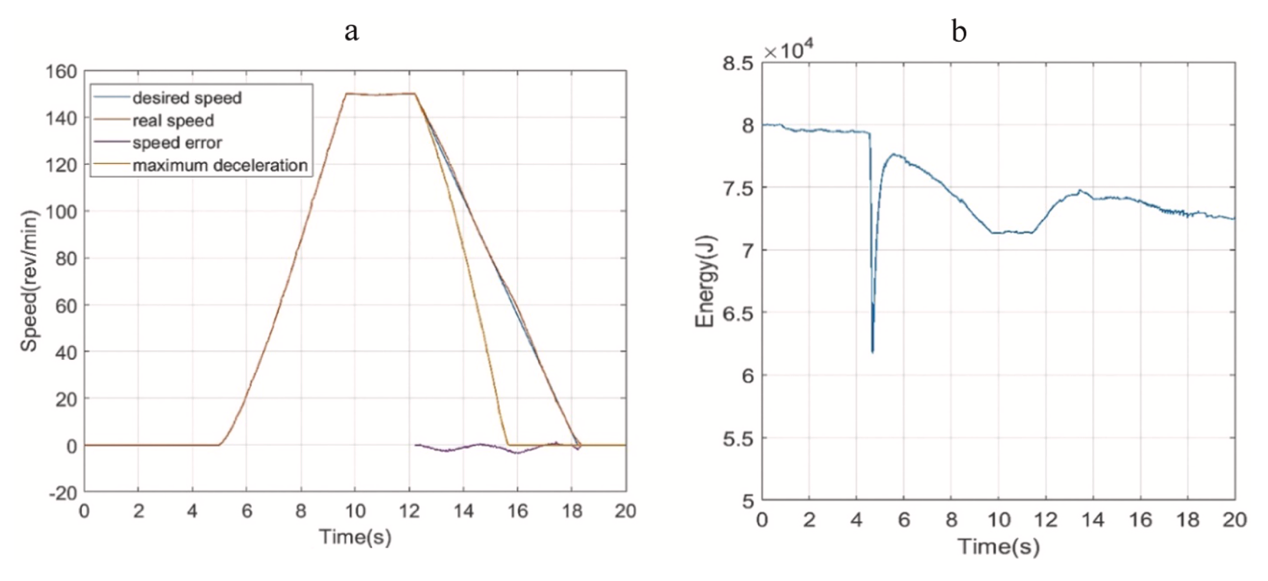
Figure 2. Plot of (a) desired versus real speed and (b) accumulator energy storage [8]
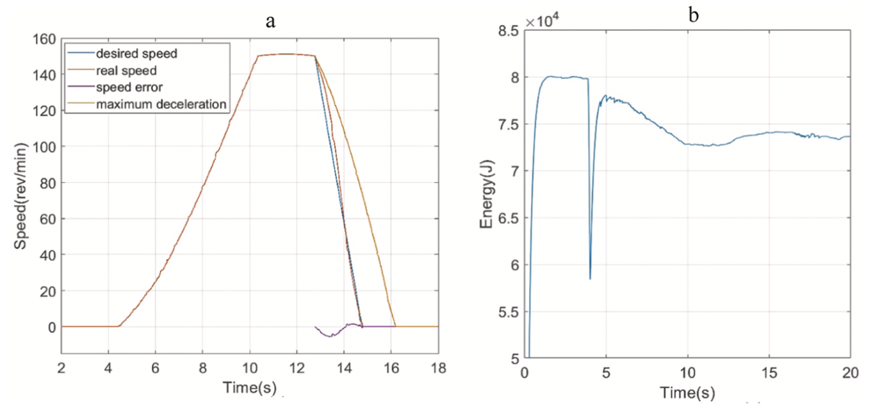
Figure 3. Plot of (a) desired versus real speed in dual braking and (b) accumulator energy storage [8]
2.2. Flywheel Energy Storage System (FESS)
Energy lost through deceleration or braking is a common aspect in automotive industry. For vehicles, energy efficiency and conservation of resources is necessary. As an approach to store and reuse lost energy, Kinetic Energy Recovery Systems (KERS) were invented, with various types and ways. For example, mechanical KERS, as shown in (figure 4), were widely used in racing car, it stores mechanical energy in a flywheel. Another type is hydraulic KERS (figure 5), it is mostly used for heavy machinery like excavators [9]. What’s more, there are Electric KERS for battery electric and hybrid electric vehicles, and hydro-electric KERS [10]. This paper is mainly focusing on Mechanical KERS involving Mechanical regenerative flywheel.
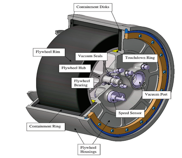
Figure 4. The flybrid flywheel used in mechanical KERS
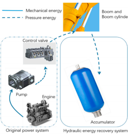
Figure 5. Schematic of hydraulic excavators with hydraulic KERS
The mechanical KERS were first widely used in Racing cars and is hardly seen in the field of street cars and other common vehicle field. Because the flywheel, KERS is not designed to be a stand-alone source of power in the vehicle, its main purpose was to provide additional power during the acceleration period. However, for vehicles in the city, it is common to continuously change the speed during the start-stop pattern, which is the most significant acceleration period [11]. In that case the Flywheel KERS seem not capable for the vehicles that runs in the city road. But this doesn’t indicate that the application of the flywheel KERS is limited. For public transportation, flywheel KERS seems to be a great option for improving energy efficiency.
The first application of flywheel KERS in buses was in the 1950s, a bus called Gyrobus. The rising interest in electric and hybrid vehicles during the late 20th centuries lead to a greater awareness of vehicles with flywheel (Table 1) [12]. Besides, there are also usages of flywheel KERS in rail vehicle. The light rail is a great example for this, for dc light rail networks, according to paper [13],in a single train system, the improvement of efficiency can be up to 21.6%,and 22.6% for multi-train, what’s more the results also suggested that. “Trackside flywheel energy storage was shown to be effective in improving voltage sag by 29.8% and reducing substation loading by 30.1%”. Apart from that, Volvo had already made experiment of flywheel KERS on road car, the result shows that it has the potential to reduce fuel consumption by up to 25% compared with the six-cylinder turbo engine at a comparable performance level [14].
Table 1. Flywheel vehicles(public transportation) [4]
Nr. | Year | Name | Developer/Company | Country | Content of Energy [kWh] | Max. Speed | Fly wheel Mass [kg] |
Road Vehicles | |||||||
1 | 1953 | Gyrobus | Oerlikon Werke | CH | 9.15 | 3000 | 1500.0 |
2 | 1961 | Gyreacta | Robert Clerk | GB | - | 15000 | 100.0 |
3 | 1979 | Stockholm City Bus | Volvo | SE | - | 10000 | 335.0 |
4 | 1981 | M.A.N Test Bus | MAN | D | 1.50 | 12000 | 104.0 |
5 | 1985 | New York Bus System | Garrett Corp | USA | 16.00 | 16000 | 340.0 |
6 | 1988 | Munich City Bus | MAN/Magnet Motor | D | 2.75 | 11000 | 181.0 |
7 | 1995 | O-Bus Basel | Neoplan/Magnet Motor | - | - | - | - |
8 | 1998 | CCM Trolleybus | CCM | DK | 2.00 | - | - |
9 | 2002 | Advanced Technology Transit Bus | Northrop Grumman | USA | 2.00 | 40000 | - |
10 | 2004 | PHILEAS | CCM | - | - | - | - |
11 | 2006 | Auto Tram | Fraunhofer Institut | D | 4.00 | 23000 | 300 |
12 | 2009 | Torotrac Fly Bus | Ricardo Kinergy/Torotrac | GB | 0.28 | - | - |
Rail Vehicles | |||||||
1 | 1860 | Schuberski Lok | Leutnant Z. Schuberski | RUS | 31.67 | - | 5000.0 |
2 | 1948 | British Rail Class 70 | GB | - | - | - | |
3 | 1974 | New York Subway | Garrett Corp | USA | - | 14000 | 4x68.0 |
4 | 1975 | Advanced Conept Train | Boeing Vertol Comp | USA | 4.50 | 11000 | |
5 | 1992 | PPM 50 Railcar | Parry People Movers | GB | 3.75 | 2600 | 720.0 |
6 | 2001 | ULEV-TAP 1 | CCM | - | 400 | - | - |
7 | 2004 | Lirex MDS K5 | ALSTOM | D | 2x2.00 | 12000 | - |
8 | 2006 | Lirex MDS K6 | ALSTOM | D | 2x6.00 | 21000 | - |
The system has three separate operating states, which is the charging process, converting other types of energy into the mechanical energy of the flywheel, the discharge process, transmitting the stored energy using the drive motor as a generator and the flywheel speed experiences a decrease in this process, and lastly the maintenance state, keeping the energy loss of the fly wheel at a low level.
By looking through these process, it can be seen that the performance of flywheel energy recovery system mainly depends on several factors, which is the material of the rotor , the type of the rotor, the bearing used in the system, and the strategy of charge and discharge [15]. For material improvements, Kim S et al. [16] designed and fabricated a hub made of composite materials for a flywheel rotor, further improved the energy stored in the system and accelerates the process of releasing energy, thus increasing the power. V. Kale, M. Secanell [17], studied and concluded that” press-fitted multi-rim composite rotors with specific material sequences could outperform single rim composite and metal flywheels, in terms of total energy or specific energy.” As for rotor enhancements, significant innovation has been proposed in the past several years (Table2). They all showed great improvement in the efficiency. As for bearing innovation, a study by Murakami et al. [18] developed a superconducting magnet bearing using a parament repulsive magnet through this, the flywheel could be driven up to 10,000 rpm along with strong axial suspension force. The innovation above showed that the technology improvement of flywheel energy recovery system made it applicable and has great potential in improving the overall efficiency of modernized vehicles.
Table 2. Performance comparison of various motors [7]
Performance | Asynchronous machine | Reluctance machine | Permanent magnet machine |
Power | High | Low | Low |
Specific power | 0.7 | 0.7 | 12 |
Rotor loss | Copper, iron | Iron | None |
Rotation loss | Can be removed by demagnetization | Can be removed by demagnetization | Irremovable |
Efficiency % | 93 | 93 | 95 |
Torque ripple | Medium | High | Medium |
Speed | Medium | High | Low |
Loss field | None | None | Have |
Cost | Low | Low | High |
2.3. Electric Turbo Compound (ETC)
2.3.1. CO2 reduction. Electric Turbo Compounding (E-TC) means installing a motor-generator unit on the exhaust side. The energy of the exhaust gas is reused. At an early stage, people invented the Lundell generator which had the same purpose as ETC. The total ETC can be divided into three different structures: sE-TC, pE-TC and eA-TC. In the sE-TC system, the power turbine is located below the turbocharger and must operate at lower pressure conditions. Especially for a light-duty engine, commercially turbines could not take over the role of the power turbine [19]. The turbocharger in pE-TC is usually installed between the intake and exhaust pipes of the engine. Its layout avoids the demanding requirements of a power turbine. However, it cannot solve the turbo-lag problem [19]. The eA-TC system includes an electric machine coupling on the shaft of the turbocharger. The electric machine can be used either to reuse energy from the exhaust or to provide additional power to the turbocharger shaft during acceleration [19].
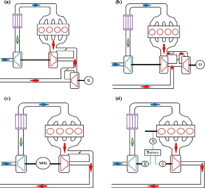
Figure 6. Different layouts of E-TC (a) sE-TC (b) pE-TC (c) eA-TC (d) EBTG [19].
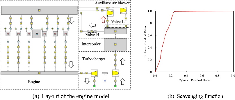
Figure 7. Layout of the engine model [20].
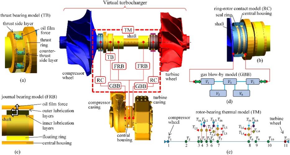
Figure 8. Graphical representation of a virtual turbocharger [21]
ETC can provide considerable power and efficiency gains at high loads. At low loads, however, ETC does not provide a significant improvement, or even diminishes it somewhat, and the advantages of ETC for larger vehicles are clearly superior to those for smaller vehicles. The paper focuses on how to recover engine waste heat, improve fuel economy and achieve the CO2 reduction through Electric Turbo-Compound (ETC) technology. Applying ETC technology to a turbocharged petrol vehicle and testing the associated integration effects. A motor - generator unit is added to the whole system. At low loads, additional power can be provided by using an electric motor to assist the turbocharger. The electric motor can electrically drive the turbocharger when exhaust gas energy is low, increasing intake pressure and improving engine performance. There is an extra battery and an inverter in the layout in order to recycle the energy. By monitoring and optimising the distribution and utilisation of energy in real time, the efficiency of the ETC system can be maximised in low load situations. Modelling and simulating dynamic analysis of vehicle powertrains to compare the CO2 reduction and the fuel efficiency [22].
The application of the ETC can obviously reduce CO2 emissions up to 5% [22]. Another paper I. Arsie, A. Cricchio, C. [23] shows that combine the application of the ETC system with the Stop and Start strategy could push the percentage of CO2 reduction up to 6.6%.
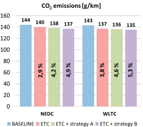
Figure 9. Different CO2 emissions [22]
Many of the above experimental conclusions are reflected in the high engine load operating conditions which means power of turbine should outweigh the compressor [22]. At low load conditions the turbine needs to close the turbine blades to achieve the required boost pressure. That also shows the inefficiency of ETC in low load operating conditions [24]. The turbocharger has two thresholds to limit itself [23]. Attempts can be made to lower the lower threshold and increase the upper threshold to widen the operating range of the turbine. The ability to make the turbine work over a wider range and re-work in zones where it was not responding. And some more attentions can be focused on improving the efficiency of ETCs under low load conditions like changing the turbine blade material or its own structure.
2.3.2. Fuel efficiency. In gasoline internal combustion engines, about 40% of the fuel energy is wasted in the exhaust gases and another 30% is dissipated through the coolant [25]. This kind of situation significantly reduced energy efficiency due to the Substantial energy loss. ETC was created to solve the problem of energy waste. The flowing will focus on how can ETC make a vehicle more fuel efficient. An experiment is set up to compare fuel economy under different scenarios, thus providing a reliable way of thinking about saving fuel. It carries out three different structures system A, B and C. Two road models US06 and FTP75 are cited in the test. US06 is developed to describe the high loads working environment. And FTP75 is developed to describe low engine loads like driving on the urban road. System A integrates an electrical generator into the turbine shaft to convert additional energy into electricity and limit boost pressure. System B recovers additional energy downstream of the turbocharger by connecting the power turbine and turbocharger in series. Turbocharger and power turbine in parallel with two additional throttle valves to form the system C [26]. The final conclusion is reached by evaluating the energy consumption in different scenarios.
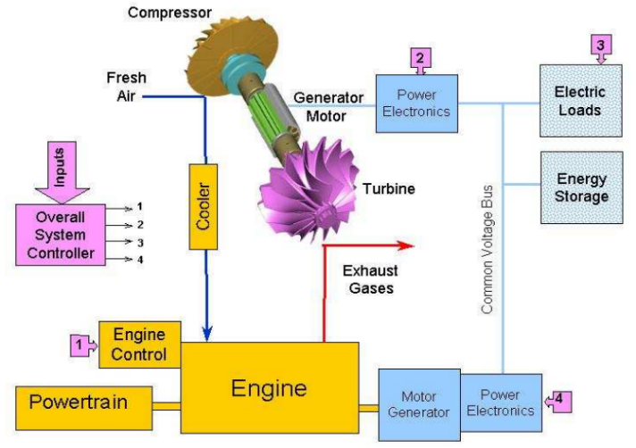
Figure 10. Electric Turbo compound System Diagram [27]
The 2 different simulations built by W. Wei, W. Zhuge et al. shows that System C’s fuel economy improves by 4.0 % in the US06 driving cycle and 1.6 % in the FTP75 driving cycle [26]. The minimum fuel consumption of the electric compound engine is consistently lower than that of the reference engine, by 5.1 to 8.3% [28]. Through the experimental data, it can be clearly understood that ETC has a significant improvement in vehicle fuel economy. However, if comparing the results for high and low loads, the efficiency at low loads is not as good as at high loads. Due to the addition of a power turbine in System C, it can be noticed that both are still more efficient in System C than in System A at low loads [25]. Giving the turbine some extra power at low loads can be an effective way to improve some fuel efficiency. A paper from A. Mohd Noor, R. Che Puteh et al. indicated that when a downstream power turbine is fitted, engine performance is compromised as the power turbine applies a degree of back pressure in the exhaust system [25]. Considering reducing the size of the power turbine is also a way to improve fuel economy. The change of the material of the turbocharger also provides with a way to reduce the flywheel inertia.
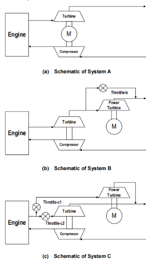
Figure 11.Three different systems [26]
2.3.3. Energy recovery. About 33% of the fuel energy in a petrol engine is lost through the exhaust gases. Solving the problem of energy waste is key to economic viability. ETC can save energy by optimising the geometrical design and speed control of the turbine generator. Control the flow distribution between the turbocharger and the turbo-generator to optimally recover energy from the exhaust gases. An experiment is carried out to compare the energy efficiency of two different ETC structures VNT and FGT on two road models US06 and FTP75. FGT applies two throttles to ETC, one for the turbo and another for the generator. In the VNT structure, the turbo-generator is controlled by a VNT and the throttle-2 is removed.
At engine speed of 6000 rpm, the maximum of the efficiency of output power improvement is 8%, At high load operating conditions, the performance of the VNT system is higher than the FGT by 0.3% [29]. Maximum efficiency gains are achieved when the engine throttle is fully open and the throttle upstream of the turbocharger is fully closed at 44 per cent load conditions.
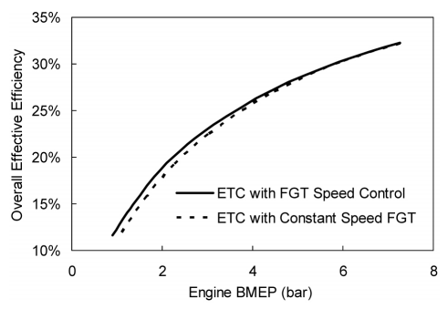
Figure 12. Effects of the power turbine speed control (part load, 2500 rpm)
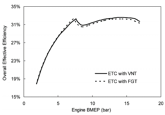
Figure 13. comparison of ETC system with VNT and FGT (part load, 2500 rpm)
The definition and formula for calculating the efficiency is provided in the experimental results data. the overall effective efficiency of the engine system is equal to the engine output divided by the sum of the fuel consumption rate and the electrical power output [29].
\( {η_{IES=}}\frac{{P_{e}}+{P_{t}}}{{\dot{m}_{f}}{H_{u}}} \)
It can be seen from the equation that reducing the low-level heating value of the fuel improves the overall energy efficiency. And the fuel heat dissipation can be accelerated as much as possible by changing the rate of heat transfer during fuel pipeline transfer. Similarly, reducing fuel consumption is a way to improve efficiency. Setting limits on injectors to reduce fuel feeds addresses the issue of energy.
2.4. Thermoelectric
The application of thermoelectric technology in vehicles is mainly reflected in the device of thermoelectric generator, which contains thermoelectric material modules, radiators, thermal conductive plates, electronic components, and other components. The Unileg thermoelectric generator (TGEs) [2] is the most representative, which is able to convert waste heat from exhaust gases into reusable electricity. In addition, another application of thermoelectric technology in vehicles is to use the chemical heat or chemical properties of the vehicle exhaust gas to produce hydrogen, and then convert the chemical energy of hydrogen into electrical energy stored in the fuel cell.
The current problem with TGEs is that the heat output will greatly affect its working efficiency, and researchers have adjusted the number and height of its legs to reduce its heat output in order to improve efficiency. Hydrogen production efficiency affects the performance and battery life of fuel cells. To address this issue, Sittichompoo, Nozari et al [2] used catalytic ammonia decomposition to produce hydrogen to recover waste gas energy, while M. Umar, M. R. Menezes et al. [30] use diesel engine waste heat recovery as bioethanol fuel product hydrogen.
Reducing the height of the connecting pins from 12 mm to 8 mm can increase the output power of the system by 31%, however, the efficiency shows no significant sensitivity to the change in leg height, with only a slight decrease of 1.45%. The reaction rate and yield of hydrogen produced in the hydrogen production experiment have been improved, and converting the produced hydrogen into electricity for storage in the fuel cell can improve fuel economy by 32%.
In automobiles, about 70% of fuel energy is lost in the form of waste heat through engine exhaust and coolant, and how to use this lost energy is a problem that researchers have been studying. Nicholas Kempf, Yanliang Zhang et al. [31] improved the heat conversion efficiency by optimizing the structure of TEG. A high-temperature thermoelectric generator (TEG) was experimentally simulated to convert engine exhaust waste heat into electrical energy, and the TEG was optimized to consist of 72 nanostructured Heusler tem half blocks [32]. Use of silicon carbide heat exchangers and SS 444 heat exchangers to provide fuel efficiency.
The experimental results show that the fuel efficiency on the highway is increased by 2.5% and 2.0%, respectively. To further improve fuel efficiency can also be achieved by increasing the ZT value of the material, using a cascade/grading module with higher thermoelectric conversion efficiency, and/or using a multistage teg with low temperature TEM in the exhaust stream. The significant influence of waste heat recovery on vehicle performance. However, the potential for efficiency gains remains great. Increasing the ZT value of the material, adopting cascaded or graded modules with superior thermoelectric conversion efficiency, and implementing multistage teg in the exhaust stream at different temperature levels all offer interesting possibilities for further development. In essence, the ability to capture waste heat and convert it into usable energy not only demonstrates sustainable engineering, but also the ability to capture and convert it into usable energy. And it reflects the broader need to optimize resource use.
Vehicle thermoelectric technology: waste heat to electricity, chemical reaction to produce hydrogen, improve efficiency and fuel economy. Adjust the structure, improve the efficiency of hydrogen production, and convert hydrogen into electricity to improve economy.
Thermal conversion of waste gas to electricity improves highway economy. High ZT material, cascade module, multistage thermoelectric generator to increase efficiency. Sustainable engineering, resource optimization.
2.5. Rankine cycle waste heat recovery system
The Rankine Cycle Waste Heat Recovery System is a technology employed to gather and make use of the waste heat generated by industrial processes or internal combustion engines. The system operates based on the Rankine cycle, which is a thermodynamic cycle that changes heat into mechanical work. In this system, the waste heat produced by exhaust gases or other sources is employed to create steam or other working fluids. The working fluid is then directed through a turbine, which drives a generator to generate electricity or mechanical work. By capturing the waste heat that would otherwise be lost, the system can be effectively utilized to improve energy efficiency and reduce greenhouse gas emissions, making Rankine Cycle Waste Heat Recovery Systems an environmentally sustainable option for a broad variety of industries and applications. By turning waste heat into useful energy, the technology contributes to the overall energy efficiency of the process and helps satisfy sustainability objectives [33].
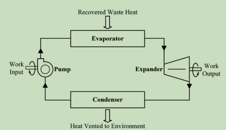
Figure 14. The Rankine Cycle
In the context of internal combustion engines in automobiles, a notable problem is that a significant amount of fuel energy is wasted as heat, resulting in reduced fuel efficiency and increased emissions. This situation poses environmental challenges. A solution is proposed in the form of Rankine Cycle (RC) technology, which harnesses this waste heat and converts it into usable energy to improve fuel efficiency and reduce emissions. The study methodically examined a range of RC system designs, expander variants, suitable working fluids, and strategies for seamless integration of these systems into passenger vehicles. The results of the study show that the implementation of RC systems has the potential to improve vehicle efficiency by a significant margin of 2% to 8%, depending on the specific system configuration and operating conditions. Notably, even greater efficiency gains can be achieved by integrating these RC systems with cooling systems for hybrid vehicle power electronics. The research also highlights the critical importance of selecting expanders and working fluids that are carefully matched to the vehicle’s unique specifications. While acknowledging the challenges of integration and added weight, the Rankine cycle offers a promising way to meet emissions standards and improve overall vehicle efficiency. In internal combustion engines, a large amount of fuel energy is lost as heat in the exhaust gas and engine coolant, and the Organic Rankine Cycle (ORC) has emerged as a promising automotive waste heat recovery technology. This study focuses on the potential of ORCs to recover waste heat from exhaust and coolant sources. ORC uses low-boiling organic fluids to convert heat into high-pressure gas, effectively improving engine efficiency. The study examines the feasibility of using Genetron 245fa, a non-chlorinated hydrocarbon, in ORCs, highlighting issues such as available waste heat, temperature-related efficiency limitations, and potential engine inefficiencies due to increased backpressure limits. By analyzing the performance of a 1.8-liter gasoline engine using an exhaust and coolant ORC system, the study shows that exhaust ORC can improve fuel efficiency by up to 6.4% at high loads, while coolant ORC can improve efficiency by up to 2.8%. Combining the two systems can improve fuel efficiency by up to 8.2%. However, these gains should be considered in light of electromechanical conversion losses, reduced engine thermal efficiency due to back pressure, and transient operation challenges. While the benefits of the ORC system are significant, challenges such as additional weight, cost, complexity, and transient operation issues should be addressed when considering large-scale production. Overall, the study highlights the potential for ORC systems to improve vehicle fuel efficiency and meet emissions standards, while recognizing the need to mitigate the challenges associated with these systems. The discussion highlighted the enormous potential benefits of the ORC system in terms of fuel economy. However, it is critical to consider the trade-offs between these advantages and the associated disadvantages such as increased weight, cost, complexity, and transient operation challenges. The results of this study provide valuable insights into the advancement of passenger vehicle heat recovery systems and effectively outline their advantages and limitations. In conclusion, this study confirms the ability of ORC systems, especially those that recover heat from exhaust gases and coolant, to improve the fuel efficiency of passenger vehicles. Despite the obvious advantages, barriers such as transient operation issues and efficiency loss need to be addressed when integrating these systems into mass production [34].
2.6. Comparation
Different technologies will have different advantages. In terms of energy efficiency regenerate braking has the most significant energy efficiency of 92%, followed by flywheel at 80%. For ETC and thermoelectric both of them have better fuel economy around 5%-8% and ETC also has obvious CO2 reduction. Rankin cycle can improve the overall energy efficiency of the vehicle up to 8.2%.Collectively, regenerate braking is more widely used and more efficient
3. Conclusion
Electrified powertrain and energy management strategy (EMS) has the access to significantly reduce the waste of the energy among the exhaust, gain more fuel efficiency and reach some CO2 reduction. The whole system can be divided into different technical. The paper talks about Regenerative braking, ETC, Thermoelectric, Flywheel energy storage system (FESS) and Rankin cycle. All parts can be made more efficient by recovering energy from the vehicle’s working processes such as energy from exhaust gases, vehicle inertia, etc.
Each section is summarised in more detail below.
• At high loads, the ETC system can compensate for the additional power supplied to the engine via the electric motor. So, it has a better performance at high loads than the low loads. lt can improve more 2.5% fuel efficiency in the high loads.
• Under high load operating conditions, ETC is more effective i.e. significantly reduces CO2 emissions up to 6%. The generator section would reuse the energy in the CO2 to help with turbine start-up. The ETC can recharge the battery and relax the alternator load on the engine in order to achieve the efficiency.
• The hydraulic system not only delivers rapid braking performance but also achieves a commendable 3.35% energy recovery enhancement, offering both safety and efficiency benefits.
• The innovative electro-hydraulic composite braking system’s ability to capture and repurpose around 9% of wasted energy presents a promising opportunity for significantly reducing fuel consumption. Experimental results further validate its superior performance, with a 3.35% energy recovery increase and 92% efficiency compared to conventional battery-based alternatives.
• Vehicle thermoelectric technology: waste heat to electricity, chemical reaction toproduce hydrogen, improve efficiency and fuel economy. Adjust the structure, improvethe efficiency of hydrogen production, and convert hydrogen into electricity to improve economy.
• Thermal conversion of waste gas to electricity improves highway economy. High ZT material, cascade module, multistage thermoelectric generator to increase efficiency. Sustainable engineering, resource optimization.
• The expander is a key component of the Rankine cycle system, and this paper is dedicated to finding the most suitable expander for passenger cars, as well as various Rankine cycle configurations, expander types, working fluid options, and vehicle integration strategies. Rankine cycle is one of the promising methods for energy recovery.
• This study demonstrates the feasibility of Organic Rankine Cycle (ORC) technology for recovering waste heat from exhaust gases and coolant in hybrid passenger vehicles, resulting in improved fuel efficiency. The combination of exhaust gas- and coolant-based ORC resulted in a power increase of 5.1 percent.
• By reviewing existing studies, FESS can recover over 70% of the energy lost during deceleration, and with the improvement on the motor and the bearing, the flywheel reaches a much higher spinning speed, about 15,000-17,000 rpm, thus making it possible to bring its efficiency to the next level. FESS also has the fuel efficiency at about 30%.
• The FESS has a wide coverage and longer development time, with more technology base, its easier to apply to public vehicles and aircrafts. However, there is rarely usage of FESS for road cars and FESS has several inevitable drawbacks, which is the heavy weight that is used to provide kinetic energy, and the repairing cost when failure happens.
Thermoelectric technology in vehicles involves thermoelectric generators (TEGs) that convert waste heat into electricity and harness chemical properties for hydrogen production, enhancing vehicle efficiency and fuel economy. This technology showcases sustainable engineering and optimal resource utilization in vehicles. The hydraulic system’s response rate provides the fastest braking performance, which outweighs the disadvantages of the system. Also, because hydraulic system does not require battery to store energy, it has a higher efficiency than traditional battery strategy. Rankine’s recirculating waste heat recovery systems offer several benefits, including improved fuel efficiency, reduced carbon emissions, and efficient conversion of exhaust and coolant waste heat into usable power for the vehicle. The ETC system recovers energy from the exhaust stream to generate electrical energy to provide additional power to the engine, thus improving fuel efficiency. Recycling exhaust gases can also help reduce CO2 emissions. Turbo lag can also be reduced by using an electric generator to power the turbocharger. Rankine’s recirculating waste heat recovery systems offer several benefits, including improved fuel efficiency, reduced carbon emissions, and efficient conversion of exhaust and coolant waste heat into usable power for the vehicle.
Acknowledgement
Youtian Cao and Chengchuan Shu contributed equally to this work and should be considered co-first author
References
[1]. T. Han, B. Zeng, and Y. Tong, “Theoretical study on energy recovery rate of regenerative braking for hybrid mining trucks with different parameters,” J. Energy Storage, vol. 42, p. 103127, Oct. 2021, doi: 10.1016/j.est.2021.103127.
[2]. W.-H. Chen, T.-H. Huang, G. L. Augusto, R. Lamba, C. Maduabuchi, and L. H. Saw, “Power generation and thermal stress characterization of thermoelectric modules with different unileg couples by recovering vehicle waste heat,” J. Clean. Prod., vol. 375, p. 133987, Nov. 2022, doi: 10.1016/j.jclepro.2022.133987.
[3]. L. Zhang and X. Cai, “Control strategy of regenerative braking system in electric vehicles,” Energy Procedia, vol. 152, pp. 496–501, Oct. 2018, doi: 10.1016/j.egypro.2018.09.200.
[4]. S. Bai and C. Liu, “Overview of energy harvesting and emission reduction technologies in hybrid electric vehicles,” Renew. Sustain. Energy Rev., vol. 147, p. 111188, Sep. 2021, doi: 10.1016/j.rser.2021.111188.
[5]. Q. He, Y. Yang, C. Luo, J. Zhai, R. Luo, and C. Fu, “Energy recovery strategy optimization of dual-motor drive electric vehicle based on braking safety and efficient recovery,” Energy, vol. 248, p. 123543, Jun. 2022, doi: 10.1016/j.energy.2022.123543.
[6]. F. Atkins, “18 - Integration and performance of regenerative braking and energy recovery technologies in vehicles*,” in Alternative Fuels and Advanced Vehicle Technologies for Improved Environmental Performance (Second Edition), R. Folkson and S. Sapsford, Eds., in Woodhead Publishing Series in Energy. Woodhead Publishing, 2022, pp. 545–568. doi: 10.1016/B978-0-323-90979-2.00005-6.
[7]. D. Yadav, R. Kumar, U. Kulshrestha, A. Jain, and S. Rani, “Enhancement of fuel efficiency in heavy duty vehicles through integrated module of TEG, piezoelectric and regenerative braking solutions,” Mater. Today Proc., vol. 63, pp. 1–5, Jan. 2022, doi: 10.1016/j.matpr.2021.10.372.
[8]. F. Khajvand, M. Zareinejad, S. Mehdi Rezaei, and K. Baghestan, “Design and implementation of a series hydraulic hybrid propulsion system to increase regenerative braking energy saving range,” Energy Convers. Manag., vol. 279, p. 116754, Mar. 2023, doi: 10.1016/j.enconman.2023.116754.
[9]. Boretti, “Kinetic Energy Recover Systems for Racing Cars,” in Kinetic Energy Recovery Systems for Racing Cars, SAE, 2013, pp. i–v. Accessed: Aug. 06, 2023. [Online]. Available: https://ieeexplore.ieee.org/document/8505601
[10]. R. Kapoor and C. M. Parveen, “Comparative Study on Various KERS,” 2013.
[11]. T. Mathews, “FLYWHEEL BASED KINETIC ENERGY RECOVERY SYSTEMS (KERS) INTEGRATED IN VEHICLES,” Int. J. Eng. Sci. Technol., vol. 5, 2013.
[12]. Buchroithner, I. Andrasec, and M. Bader, “Optimal system design and ideal application of flywheel energy storage systems for vehicles,” in 2012 IEEE International Energy Conference and Exhibition (ENERGYCON), Florence, Italy: IEEE, Sep. 2012, pp. 991–996. doi: 10.1109/EnergyCon.2012.6348295.
[13]. M. Gee and R. W. Dunn, “Analysis of Trackside Flywheel Energy Storage in Light Rail Systems,” IEEE Trans. Veh. Technol., vol. 64, no. 9, pp. 3858–3869, Sep. 2015, doi: 10.1109/TVT.2014.2361865.
[14]. “Volvo Cars’ tests of flywheel technology confirm fuel savings of up to 25%,” Green Car Congress. https://www.greencarcongress.com/2013/04/kers-20130425.html (accessed Aug. 06, 2023).
[15]. Bamisile, Z. Zheng, H. Adun, D. Cai, N. Ting, and Q. Huang, “Development and prospect of flywheel energy storage technology: A citespace-based visual analysis,” Energy Rep., vol. 9, pp. 494–505, Oct. 2023, doi: 10.1016/j.egyr.2023.05.147.
[16]. S. J. Kim, K. Hayat, S. U. Nasir, and S. K. Ha, “Design and fabrication of hybrid composite hubs for a multi-rim flywheel energy storage system,” Compos. Struct., vol. 107, pp. 19–29, Jan. 2014, doi: 10.1016/j.compstruct.2013.07.032.
[17]. V. Kale and M. Secanell, “A comparative study between optimal metal and composite rotors for flywheel energy storage systems,” Energy Rep., vol. 4, pp. 576–585, Nov. 2018, doi: 10.1016/j.egyr.2018.09.003.
[18]. Murakami, Y. Zhao, and T. Tashiro, “Stabilization of a Magnetic Repulsive Levitation Flywheel System Using a High-Efficiency Superconducting Magnetic Bearing,” Actuators, vol. 11, no. 7, Art. no. 7, Jul. 2022, doi: 10.3390/act11070180.
[19]. D. Zi, L. Zhang, B. Chen, and Q. Zhang, “Study of the electric-booster and turbo-generator system and its influence on a 1.5 L gasoline engine,” Appl. Therm. Eng., vol. 162, p. 114236, Nov. 2019, doi: 10.1016/j.applthermaleng.2019.114236.
[20]. M. Yang et al., “Matching method of electric turbo compound for two-stroke low-speed marine diesel engine,” Appl. Therm. Eng., vol. 158, p. 113752, Jul. 2019, doi: 10.1016/j.applthermaleng.2019.113752.
[21]. P. Novotný, P. Kudláček, and J. Vacula, “Explanation of the mechanisms of unsteady gas flow through the turbocharger seal system, including thermal and structural interactions,” Propuls. Power Res., vol. 12, no. 2, pp. 180–198, Jun. 2023, doi: 10.1016/j.jppr.2023.05.003.
[22]. Arsie, A. Cricchio, C. Pianese, V. Ricciardi, and M. D. Cesare, “Evaluation of CO2 reduction in SI engines with Electric Turbo-Compound by dynamic powertrain modelling,” IFAC-Pap., vol. 48, no. 15, pp. 93–100, Jan. 2015, doi: 10.1016/j.ifacol.2015.10.014.
[23]. Arsie, A. Cricchio, C. Pianese, V. Ricciardi, and M. De Cesare, “Modeling Analysis of Waste Heat Recovery via Thermo-Electric Generator and Electric Turbo-Compound for CO2 Reduction in Automotive SI Engines,” Energy Procedia, vol. 82, pp. 81–88, Dec. 2015, doi: 10.1016/j.egypro.2015.11.886.
[24]. García, J. Monsalve-Serrano, S. Martinez-Boggio, and P. Gaillard, “Emissions reduction by using e-components in 48 V mild hybrid trucks under dual-mode dual-fuel combustion,” Appl. Energy, vol. 299, p. 117305, Oct. 2021, doi: 10.1016/j.apenergy.2021.117305.
[25]. Mohd Noor, R. Che Puteh, S. Rajoo, U. M. Basheer, M. H. Md Sah, and S. H. Shaikh Salleh, “Simulation Study on Electric Turbo-Compound (ETC) for Thermal Energy Recovery in Turbocharged Internal Combustion Engine,” Appl. Mech. Mater., vol. 799–800, pp. 895–901, Oct. 2015, doi: 10.4028/www.scientific.net/AMM.799-800.895.
[26]. W. Wei, W. Zhuge, Y. Zhang, and Y. He, “Comparative Study on Electric Turbo-Compounding Systems for Gasoline Engine Exhaust Energy Recovery,” in Volume 5: Industrial and Cogeneration; Microturbines and Small Turbomachinery; Oil and Gas Applications; Wind Turbine Technology, Glasgow, UK: ASMEDC, Oct. 2010, pp. 531–539. doi: 10.1115/GT2010-23204.
[27]. M. Algrain, “Controlling an Electric Turbo Compound System for Exhaust Gas Energy Recovery in a Diesel Engine Marcelo C. Algrain,”.
[28]. E. Pipitone and S. Caltabellotta, “The Potential of a Separated Electric Compound Spark-Ignition Engine for Hybrid Vehicle Application,” J. Eng. Gas Turbines Power, vol. 144, no. 4, p. 041016, Apr. 2022, doi: 10.1115/1.4053393.
[29]. W. Zhuge, L. Huang, W. Wei, Y. Zhang, and Y. He, “Optimization of an Electric Turbo Compounding System for Gasoline Engine Exhaust Energy Recovery,” presented at the SAE 2011 World Congress & Exhibition, Apr. 2011, pp. 2011-01–0377. doi: 10.4271/2011-01-0377.
[30]. M. Umar, H. Nozari, M. R. Menezes, J. M. Herreros, C. S. Lau, and A. Tsolakis, “Hydrogen production from bioethanol fuel mixtures via exhaust heat recovery in diesel engines: A promising route towards more energy efficient road vehicles,” Int. J. Hydrog. Energy, vol. 46, no. 46, Art. no. 46, Jul. 2021, doi: 10.1016/j.ijhydene.2021.04.146.
[31]. N. Kempf and Y. Zhang, “Design and optimization of automotive thermoelectric generators for maximum fuel efficiency improvement,” Energy Convers. Manag., vol. 121, pp. 224–231, Aug. 2016, doi: 10.1016/j.enconman.2016.05.035.
[32]. T. Morimura, M. Hasaka, and M. Yoshimoto, “TEM observation of coexistent Heusler and half-Heusler phases in TiNi1.5Sn,” J. Alloys Compd., vol. 416, no. 1, Art. no. 1, Jun. 2006, doi: 10.1016/j.jallcom.2005.08.043.
[33]. T. Yamamoto, T. Furuhata, N. Arai, and K. Mori, “Design and testing of the Organic Rankine Cycle,” Energy, vol. 26, no. 3, pp. 239–251, Mar. 2001, doi: 10.1016/S0360-5442(00)00063-3.
[34]. Boretti, “Recovery of exhaust and coolant heat with R245fa organic Rankine cycles in a hybrid passenger car with a naturally aspirated gasoline engine,” Appl. Therm. Eng., vol. 36, pp. 73–77, Apr. 2012, doi: 10.1016/j.applthermaleng.2011.11.060.x
Cite this article
Shu,C.;Cao,Y.;Sun,T.;Zhang,T.;Wang,X. (2024). Energy recovery in automotive systems: A review of regenerative braking, flywheel, thermoelectric, rankin cycle and electric turbo compound. Applied and Computational Engineering,85,44-60.
Data availability
The datasets used and/or analyzed during the current study will be available from the authors upon reasonable request.
Disclaimer/Publisher's Note
The statements, opinions and data contained in all publications are solely those of the individual author(s) and contributor(s) and not of EWA Publishing and/or the editor(s). EWA Publishing and/or the editor(s) disclaim responsibility for any injury to people or property resulting from any ideas, methods, instructions or products referred to in the content.
About volume
Volume title: Proceedings of the 4th International Conference on Materials Chemistry and Environmental Engineering
© 2024 by the author(s). Licensee EWA Publishing, Oxford, UK. This article is an open access article distributed under the terms and
conditions of the Creative Commons Attribution (CC BY) license. Authors who
publish this series agree to the following terms:
1. Authors retain copyright and grant the series right of first publication with the work simultaneously licensed under a Creative Commons
Attribution License that allows others to share the work with an acknowledgment of the work's authorship and initial publication in this
series.
2. Authors are able to enter into separate, additional contractual arrangements for the non-exclusive distribution of the series's published
version of the work (e.g., post it to an institutional repository or publish it in a book), with an acknowledgment of its initial
publication in this series.
3. Authors are permitted and encouraged to post their work online (e.g., in institutional repositories or on their website) prior to and
during the submission process, as it can lead to productive exchanges, as well as earlier and greater citation of published work (See
Open access policy for details).
References
[1]. T. Han, B. Zeng, and Y. Tong, “Theoretical study on energy recovery rate of regenerative braking for hybrid mining trucks with different parameters,” J. Energy Storage, vol. 42, p. 103127, Oct. 2021, doi: 10.1016/j.est.2021.103127.
[2]. W.-H. Chen, T.-H. Huang, G. L. Augusto, R. Lamba, C. Maduabuchi, and L. H. Saw, “Power generation and thermal stress characterization of thermoelectric modules with different unileg couples by recovering vehicle waste heat,” J. Clean. Prod., vol. 375, p. 133987, Nov. 2022, doi: 10.1016/j.jclepro.2022.133987.
[3]. L. Zhang and X. Cai, “Control strategy of regenerative braking system in electric vehicles,” Energy Procedia, vol. 152, pp. 496–501, Oct. 2018, doi: 10.1016/j.egypro.2018.09.200.
[4]. S. Bai and C. Liu, “Overview of energy harvesting and emission reduction technologies in hybrid electric vehicles,” Renew. Sustain. Energy Rev., vol. 147, p. 111188, Sep. 2021, doi: 10.1016/j.rser.2021.111188.
[5]. Q. He, Y. Yang, C. Luo, J. Zhai, R. Luo, and C. Fu, “Energy recovery strategy optimization of dual-motor drive electric vehicle based on braking safety and efficient recovery,” Energy, vol. 248, p. 123543, Jun. 2022, doi: 10.1016/j.energy.2022.123543.
[6]. F. Atkins, “18 - Integration and performance of regenerative braking and energy recovery technologies in vehicles*,” in Alternative Fuels and Advanced Vehicle Technologies for Improved Environmental Performance (Second Edition), R. Folkson and S. Sapsford, Eds., in Woodhead Publishing Series in Energy. Woodhead Publishing, 2022, pp. 545–568. doi: 10.1016/B978-0-323-90979-2.00005-6.
[7]. D. Yadav, R. Kumar, U. Kulshrestha, A. Jain, and S. Rani, “Enhancement of fuel efficiency in heavy duty vehicles through integrated module of TEG, piezoelectric and regenerative braking solutions,” Mater. Today Proc., vol. 63, pp. 1–5, Jan. 2022, doi: 10.1016/j.matpr.2021.10.372.
[8]. F. Khajvand, M. Zareinejad, S. Mehdi Rezaei, and K. Baghestan, “Design and implementation of a series hydraulic hybrid propulsion system to increase regenerative braking energy saving range,” Energy Convers. Manag., vol. 279, p. 116754, Mar. 2023, doi: 10.1016/j.enconman.2023.116754.
[9]. Boretti, “Kinetic Energy Recover Systems for Racing Cars,” in Kinetic Energy Recovery Systems for Racing Cars, SAE, 2013, pp. i–v. Accessed: Aug. 06, 2023. [Online]. Available: https://ieeexplore.ieee.org/document/8505601
[10]. R. Kapoor and C. M. Parveen, “Comparative Study on Various KERS,” 2013.
[11]. T. Mathews, “FLYWHEEL BASED KINETIC ENERGY RECOVERY SYSTEMS (KERS) INTEGRATED IN VEHICLES,” Int. J. Eng. Sci. Technol., vol. 5, 2013.
[12]. Buchroithner, I. Andrasec, and M. Bader, “Optimal system design and ideal application of flywheel energy storage systems for vehicles,” in 2012 IEEE International Energy Conference and Exhibition (ENERGYCON), Florence, Italy: IEEE, Sep. 2012, pp. 991–996. doi: 10.1109/EnergyCon.2012.6348295.
[13]. M. Gee and R. W. Dunn, “Analysis of Trackside Flywheel Energy Storage in Light Rail Systems,” IEEE Trans. Veh. Technol., vol. 64, no. 9, pp. 3858–3869, Sep. 2015, doi: 10.1109/TVT.2014.2361865.
[14]. “Volvo Cars’ tests of flywheel technology confirm fuel savings of up to 25%,” Green Car Congress. https://www.greencarcongress.com/2013/04/kers-20130425.html (accessed Aug. 06, 2023).
[15]. Bamisile, Z. Zheng, H. Adun, D. Cai, N. Ting, and Q. Huang, “Development and prospect of flywheel energy storage technology: A citespace-based visual analysis,” Energy Rep., vol. 9, pp. 494–505, Oct. 2023, doi: 10.1016/j.egyr.2023.05.147.
[16]. S. J. Kim, K. Hayat, S. U. Nasir, and S. K. Ha, “Design and fabrication of hybrid composite hubs for a multi-rim flywheel energy storage system,” Compos. Struct., vol. 107, pp. 19–29, Jan. 2014, doi: 10.1016/j.compstruct.2013.07.032.
[17]. V. Kale and M. Secanell, “A comparative study between optimal metal and composite rotors for flywheel energy storage systems,” Energy Rep., vol. 4, pp. 576–585, Nov. 2018, doi: 10.1016/j.egyr.2018.09.003.
[18]. Murakami, Y. Zhao, and T. Tashiro, “Stabilization of a Magnetic Repulsive Levitation Flywheel System Using a High-Efficiency Superconducting Magnetic Bearing,” Actuators, vol. 11, no. 7, Art. no. 7, Jul. 2022, doi: 10.3390/act11070180.
[19]. D. Zi, L. Zhang, B. Chen, and Q. Zhang, “Study of the electric-booster and turbo-generator system and its influence on a 1.5 L gasoline engine,” Appl. Therm. Eng., vol. 162, p. 114236, Nov. 2019, doi: 10.1016/j.applthermaleng.2019.114236.
[20]. M. Yang et al., “Matching method of electric turbo compound for two-stroke low-speed marine diesel engine,” Appl. Therm. Eng., vol. 158, p. 113752, Jul. 2019, doi: 10.1016/j.applthermaleng.2019.113752.
[21]. P. Novotný, P. Kudláček, and J. Vacula, “Explanation of the mechanisms of unsteady gas flow through the turbocharger seal system, including thermal and structural interactions,” Propuls. Power Res., vol. 12, no. 2, pp. 180–198, Jun. 2023, doi: 10.1016/j.jppr.2023.05.003.
[22]. Arsie, A. Cricchio, C. Pianese, V. Ricciardi, and M. D. Cesare, “Evaluation of CO2 reduction in SI engines with Electric Turbo-Compound by dynamic powertrain modelling,” IFAC-Pap., vol. 48, no. 15, pp. 93–100, Jan. 2015, doi: 10.1016/j.ifacol.2015.10.014.
[23]. Arsie, A. Cricchio, C. Pianese, V. Ricciardi, and M. De Cesare, “Modeling Analysis of Waste Heat Recovery via Thermo-Electric Generator and Electric Turbo-Compound for CO2 Reduction in Automotive SI Engines,” Energy Procedia, vol. 82, pp. 81–88, Dec. 2015, doi: 10.1016/j.egypro.2015.11.886.
[24]. García, J. Monsalve-Serrano, S. Martinez-Boggio, and P. Gaillard, “Emissions reduction by using e-components in 48 V mild hybrid trucks under dual-mode dual-fuel combustion,” Appl. Energy, vol. 299, p. 117305, Oct. 2021, doi: 10.1016/j.apenergy.2021.117305.
[25]. Mohd Noor, R. Che Puteh, S. Rajoo, U. M. Basheer, M. H. Md Sah, and S. H. Shaikh Salleh, “Simulation Study on Electric Turbo-Compound (ETC) for Thermal Energy Recovery in Turbocharged Internal Combustion Engine,” Appl. Mech. Mater., vol. 799–800, pp. 895–901, Oct. 2015, doi: 10.4028/www.scientific.net/AMM.799-800.895.
[26]. W. Wei, W. Zhuge, Y. Zhang, and Y. He, “Comparative Study on Electric Turbo-Compounding Systems for Gasoline Engine Exhaust Energy Recovery,” in Volume 5: Industrial and Cogeneration; Microturbines and Small Turbomachinery; Oil and Gas Applications; Wind Turbine Technology, Glasgow, UK: ASMEDC, Oct. 2010, pp. 531–539. doi: 10.1115/GT2010-23204.
[27]. M. Algrain, “Controlling an Electric Turbo Compound System for Exhaust Gas Energy Recovery in a Diesel Engine Marcelo C. Algrain,”.
[28]. E. Pipitone and S. Caltabellotta, “The Potential of a Separated Electric Compound Spark-Ignition Engine for Hybrid Vehicle Application,” J. Eng. Gas Turbines Power, vol. 144, no. 4, p. 041016, Apr. 2022, doi: 10.1115/1.4053393.
[29]. W. Zhuge, L. Huang, W. Wei, Y. Zhang, and Y. He, “Optimization of an Electric Turbo Compounding System for Gasoline Engine Exhaust Energy Recovery,” presented at the SAE 2011 World Congress & Exhibition, Apr. 2011, pp. 2011-01–0377. doi: 10.4271/2011-01-0377.
[30]. M. Umar, H. Nozari, M. R. Menezes, J. M. Herreros, C. S. Lau, and A. Tsolakis, “Hydrogen production from bioethanol fuel mixtures via exhaust heat recovery in diesel engines: A promising route towards more energy efficient road vehicles,” Int. J. Hydrog. Energy, vol. 46, no. 46, Art. no. 46, Jul. 2021, doi: 10.1016/j.ijhydene.2021.04.146.
[31]. N. Kempf and Y. Zhang, “Design and optimization of automotive thermoelectric generators for maximum fuel efficiency improvement,” Energy Convers. Manag., vol. 121, pp. 224–231, Aug. 2016, doi: 10.1016/j.enconman.2016.05.035.
[32]. T. Morimura, M. Hasaka, and M. Yoshimoto, “TEM observation of coexistent Heusler and half-Heusler phases in TiNi1.5Sn,” J. Alloys Compd., vol. 416, no. 1, Art. no. 1, Jun. 2006, doi: 10.1016/j.jallcom.2005.08.043.
[33]. T. Yamamoto, T. Furuhata, N. Arai, and K. Mori, “Design and testing of the Organic Rankine Cycle,” Energy, vol. 26, no. 3, pp. 239–251, Mar. 2001, doi: 10.1016/S0360-5442(00)00063-3.
[34]. Boretti, “Recovery of exhaust and coolant heat with R245fa organic Rankine cycles in a hybrid passenger car with a naturally aspirated gasoline engine,” Appl. Therm. Eng., vol. 36, pp. 73–77, Apr. 2012, doi: 10.1016/j.applthermaleng.2011.11.060.x