


1. Introduction
With the rapid advancement of UAV technology, formation control of multi-quadcopters has become a hot research topic [1]. Formation flight can enhance system efficiency and reliability but introduces challenges such as nonlinear dynamics, external disturbances, and formation coordination. Traditional control methods struggle to meet the requirements of fast convergence and high precision simultaneously. This paper proposes a control strategy based on finite-time stability theory aimed at achieving rapid formation of multi-quadcopter systems and precise trajectory tracking. This method is expected to play a crucial role in collaborative missions in complex environments [2].
2. Multi-Quadcopter System Model and Problem Description
2.1. Quadcopter UAV dynamics model
The dynamics model of a quadcopter UAV can be described using position and attitude information. In the ground coordinate system, assuming N quadcopters, the position and attitude information of the  quadcopter are denoted by
  , where
  represents position coordinates, and
  denote roll, pitch, and yaw angles, respectively. Each aircraft's system parameters include mass m, gravitational acceleration g, and moment of inertia J [3]. By introducing virtual control inputs, the position system can be simplified to a second-order integrator model. The attitude system can be described using Euler angle velocities and angular accelerations. This model forms the basis for subsequent controller design, enabling separate consideration of position and attitude control problems.
2.2. Description of multi-quadcopter formation control problem

Figure 1. Multi-Quadcopter Formation
As shown in Fig. 1, establish an  plane coordinate system with the leader as the origin. Consider the formation control problem of 1 leader and 4 followers quadcopters. Describe the positions of the four followers respectively,

The relative positions between nodes are always kept constant, and the relative position is set to:

2.3. Coordinate System Establishment and Parameter Setting
In the ground coordinate system, assume there are n quadcopter aircraft, using  to describe the position information and attitude information of the quadcopter [4]. The expected trajectory of the leader baseline is, the initial position of follower 1 is
  , the initial position of follower 2 is (2,1,0,0,0,0)T, the initial position of follower 3 is (0,1,-1,0,0,0)T, and the initial position of follower 4 is (0,0,0,0,0,0)T. Each aircraft's system parameters are selected as follows:
  ,
,  ,
,  ,
,  , and
, and  ,(
,( ). The moment of inertia of each aircraft is: Given a finite time T=10 s, the requirement is for the aircraft's position and attitude to converge to their desired values within this time.
3. Distributed Formation Control Protocol Design
3.1. Information Exchange Strategy
The formation control strategy consists of two main parts: information exchange and formation control. In the information exchange phase, this study adopts a distributed control approach, where each quadcopter in the formation system only needs to exchange position information with its nearest neighbor [5]. Additionally, it is highly convenient to add or remove individual UAVs when malfunctions occur.
3.2. Leader-Follower Formation Control
This study adopts the leader-follower approach for formation control among the UAVs. Initially, designate one UAV as the leader, with the remaining individuals as followers. Followers align themselves around the leader and track its trajectory. The advantage of the leader-follower method lies in simplifying the structure of formation control. For example, the leader only needs to send information to follower 1, enabling follower 2 to track the leader's trajectory. Similarly, follower 1 only needs to communicate with follower 2 to achieve tracking, and so forth, thereby coordinating all UAVs in the formation.
3.3. Graph Representation and Laplacian Matrix
The interaction among n quadcopters can be described using the graph  . Here,
  represents the set of nodes, E is the set of edges, \( A=[{a_{ij}}]ϵ{R^{n×n}} \) represents the weights between adjacent nodes. If
  exists, satisfying
 , then it indicates that there is information exchange between node
  and node
  . Define the degree matrix
  , then the Laplacian matrix L of graph G is as follows:
\( L=D-A=[\begin{matrix}\sum _{j=1}^{n}{a_{1j}} & -{a_{12}} \\ \begin{matrix}-{a_{21}} \\ \\ \begin{matrix} \\ \begin{matrix}⋮ \\ \\ -{a_{n1}} \\ \end{matrix} \\ \end{matrix} \\ \end{matrix} & \begin{matrix}\sum _{j=1}^{n}{a_{2j}} \\ ⋮ \\ -{a_{n2}} \\ \end{matrix} \\ \end{matrix} \begin{matrix}⋯ & -{a_{1n}} \\ \begin{matrix} \\ \\ \begin{matrix} \\ \begin{matrix}⋯ \\ \\ \begin{matrix} \\ \\ ⋯ \\ \end{matrix} \\ \end{matrix} \\ \\ \end{matrix} \\ \end{matrix} & \begin{matrix}-{a_{2n}} \\ \\ \begin{matrix} \\ ⋮ \\ \begin{matrix} \\ \\ \sum _{j=1}^{n}{a_{nj}} \\ \end{matrix} \\ \end{matrix} \\ \end{matrix} \\ \end{matrix}]=[\begin{matrix}\sum _{jϵ{N_{1}}}{a_{1j}} & -{a_{12}} \\ \begin{matrix}-{a_{21}} \\ \\ \begin{matrix} \\ \begin{matrix}⋮ \\ \\ -{a_{n1}} \\ \end{matrix} \\ \end{matrix} \\ \end{matrix} & \begin{matrix}\sum _{jϵ{N_{2}}}{a_{2j}} \\ ⋮ \\ -{a_{n2}} \\ \end{matrix} \\ \end{matrix} \begin{matrix}⋯ & -{a_{1n}} \\ \begin{matrix} \\ \\ \begin{matrix} \\ \begin{matrix}⋯ \\ \\ \begin{matrix} \\ \\ ⋯ \\ \end{matrix} \\ \end{matrix} \\ \\ \end{matrix} \\ \end{matrix} & \begin{matrix}-{a_{2n}} \\ \\ \begin{matrix} \\ ⋮ \\ \begin{matrix} \\ \\ \sum _{jϵ{N_{n}}}{a_{nj}} \\ \end{matrix} \\ \end{matrix} \\ \end{matrix} \\ \end{matrix}] \)
3.4. Formation Generation Algorithm
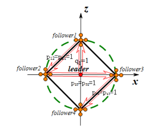
Figure 2. Tetrahedron Structure Design
The formation generation algorithm is based on the tetrahedron structure design shown in Fig. 2. Establish a three-dimensional Cartesian coordinate system  with the leader at the origin, forming a formation consisting of one leader and four followers. All followers are uniformly distributed on a virtual spherical surface centered around the leader with a radius of one unit length. Specifically, follower 1 is located on the +z-axis, while follower 2, follower 3, and follower 4 form an equilateral triangle on the
  -plane. This layout ensures the symmetry and stability of the formation. In the information exchange strategy, the leader broadcasts its position information to all followers. Each follower then computes its target position based on predefined relative positions upon receiving this information. The control algorithm can be expressed as
  , where
  is the target position of follower
  , r leader is the real-time position of the leader, and hi is the predefined relative position vector for follower
  . To maintain the formation, a distributed control algorithm such as consensus algorithms or potential-based methods is employed. These ensure that each follower accurately tracks its target position and maintains constant relative positions during the formation movement. When the formation needs to change direction or avoid obstacles, the leader updates its position and orientation. All followers then automatically adjust according to the leader's new position to maintain the overall formation.
4. Finite-Time Controller Design
4.1. Finite-Time Position Controller
The objective of the finite-time position controller is to ensure that quadcopter UAVs reach their target positions precisely within a specified time frame. Considering N quadcopter aircraft, let ( ,
,  ,
,  ) describe the position of the
  quadcopter. Define a virtual control input
  = [
= [ ,
,  ,
,  ]T, simplifying the position system to a second-order integrator model. The control law is designed as follows:

where  represents the position error,
  and
and  are positive control gains,
  and
and  are positive constants satisfying specific conditions. This design utilizes nonlinear terms to accelerate the convergence of system states, providing strong correction when the error is large and reducing control action as the target is approached. By selecting an appropriate Lyapunov function, it can be proven that the system states converge to equilibrium within a finite time. This controller ensures precise trajectory tracking and formation control, with its distributed nature enhancing system robustness and scalability. In practical applications, controller parameters may need adjustment based on specific circumstances, potentially requiring the introduction of adaptive or robust control techniques to handle uncertainties and external disturbances.
4.2. Finite-Time Attitude Controller
The finite-time attitude controller aims to converge the attitude angles ( ,
,  ,
,  ) of quadcopter UAVs to desired values within a specified time frame, considering the nonlinear characteristics of quadcopters. Define attitude error vector
  and angular velocity error
  , the controller is designed as follows:

where τ represents the control torque,  and
and  are positive control gains,
  and
and  are positive constants satisfying specific conditions, J is the moment of inertia matrix. This controller utilizes nonlinear terms to accelerate state convergence, providing strong correction for large errors and reducing control action as the target is approached. The last two terms compensate for gyroscopic torque and desired angular acceleration. By selecting an appropriate Lyapunov function, it can be proven that system states converge to equilibrium within a finite time. This design allows for rapid and precise adjustment of quadcopter attitude, suitable for formation flight and complex maneuvers. In practical applications, controller parameters may need adjustment based on specific circumstances, and filters or anti-saturation mechanisms may be introduced to address sensor noise and actuator saturation issues.
5. Simulation Experiment and Results Analysis
5.1. Simulation Environment and Parameter Settings
To validate the effectiveness of the finite-time controllers, we constructed a simulation environment using MATLAB/Simulink to model a quadcopter formation system consisting of 1 leader and 4 followers. Simulation parameters include quadcopter physical characteristics (mass of 1.5 kg, diagonal inertia matrix), optimized controller parameters, formation configuration (targeting a tetrahedron shape with a side length of 2 m), and environmental factors. The simulation was set for a duration of 30 seconds with a sampling time of 0.01 seconds, utilizing the ODE45 variable-step integration algorithm. A slight wind disturbance was introduced to simulate real-world conditions, with the leader following a spiral ascent trajectory to challenge formation control dynamically. Evaluation metrics cover position and attitude errors, formation maintenance errors, and energy consumption. These settings aim to create a simulation environment that is both realistic and challenging, comprehensively testing the performance of the control algorithms. By adjusting parameters, the robustness and adaptability of the control strategies can be assessed. Simulation results will provide critical insights for algorithm optimization and practical flight testing.
5.2. Finite-Time Position Control Simulation for Multi-Quadcopter
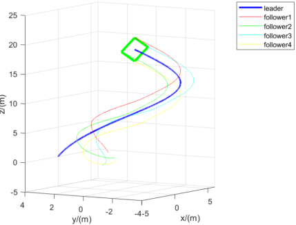
To verify the performance of the designed finite-time position controller, we conducted simulation experiments on a multi-quadcopter formation system. The simulation scenario involves one leader and four followers, totaling five quadcopter UAVs. Initial conditions were set as follows: the leader's initial position is (0, 0, 0) m, and the four followers are randomly distributed within a 5 m radius around the leader. The formation's target shape is a tetrahedron with a side length set to 2 m. The leader is tasked to follow a spiral ascent trajectory defined by the equation:
\( x(t) = 5cos(0.2t),y(t) = 5sin(0.2t),z(t) = 0.1t \)
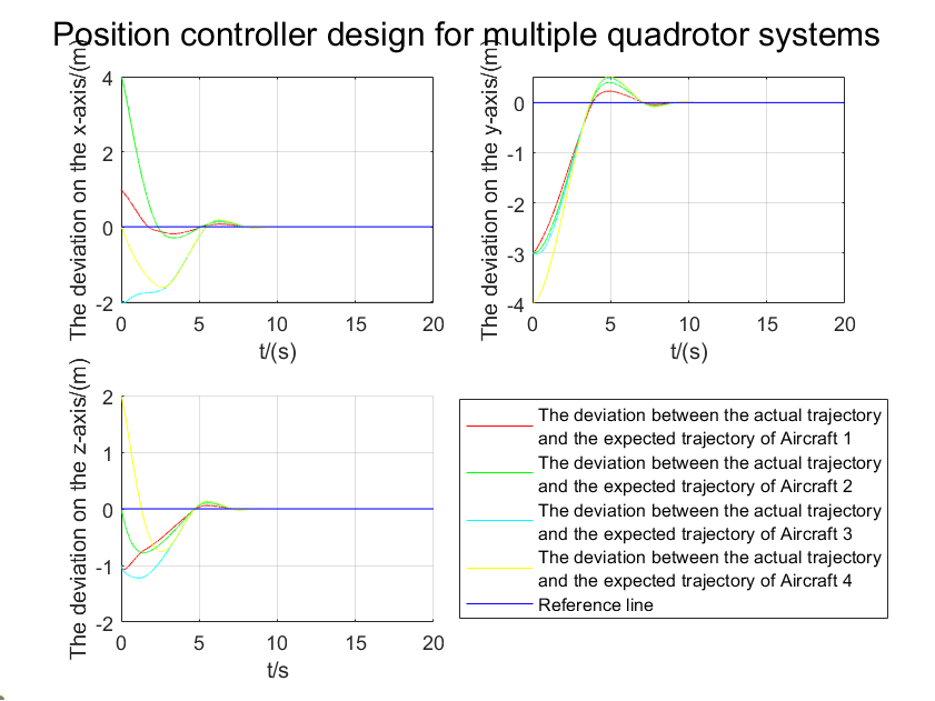
The parameters for the finite-time position controller are set as follows: k1 = 2, k2 = 3, α = 0.5, β = 1.5. These parameters have been fine-tuned through multiple iterations to achieve a balance between convergence speed and control stability. The simulation results are shown in Fig. 3.
(a)
(b)(c)
Figure 3. (a): Formation Trajectory Movement; (b): Comparison of Quadcopter Three-Axis Trajectories; (c): Convergence of Quadcopter Positions
Fig. 3(a) illustrates that the five quadcopter UAVs successfully formed the expected tetrahedron formation and coordinated flight along the leader's spiral trajectory. Initially, the followers swiftly adjusted their positions to form the formation and subsequently maintained their relative positions stably. Fig. 3(b) shows the error variation in each quadcopter's position relative to its target position. It can be observed that the position errors of all followers rapidly converged to near-zero levels within approximately 3 seconds, confirming the efficiency of the finite-time controller. Fig. 3(c) displays the formation maintenance error, i.e., deviations in relative positions between followers. The results indicate that after the initial adjustment phase, the formation maintenance error quickly decreased and remained at a low level, demonstrating the controller's effective ability to maintain the intended formation structure. To quantitatively assess control performance, the Root Mean Square Error (RMSE) of position control was calculated. During stable flight phases (t > 5s), the average RMSE was less than 0.05 m, indicating high control precision. Additionally, energy consumption of the controller was analyzed by calculating the integral of control inputs. The results showed relatively higher energy consumption in the initial phase, but after formation stabilization, energy consumption significantly decreased and remained at a low level. Overall, the simulation results confirm that the designed finite-time position controller can rapidly and accurately achieve formation generation and maintenance for multi-quadcopter formations. It maintains good tracking performance during dynamic flight, exhibiting advantages such as fast convergence, high precision, and energy efficiency. These findings provide a reliable theoretical basis for practical applications.
5.3. Simulation of Finite-Time Attitude Control for Multi-Quadcopter
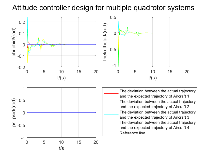
To evaluate the performance of the designed finite-time attitude controller, we conducted a simulation of attitude control for a multi-quadcopter formation system. The simulation scenario is similar to the position control simulation, involving one leader and four followers, totaling five quadcopter UAVs. The initial conditions for the simulation were set as follows: all quadcopters had initial attitude angles  set to (0, 0, 0) radians. The leader was tasked with executing a complex attitude maneuvering task, which includes simultaneous changes in all three attitude angles to test the controller's performance. The specific tasks are as follows:
\( {ϕ_{d}}(t)=0.2sin(0.5t) \) , \( {θ_{d}}(t)=0.15cos(0.5t) \) , \( {φ_{d}}(t)=(0.1t) \)
The parameters for the finite-time attitude controller are set as follows:  ,
,  ,
,  ,
,  . These parameters have been refined through iterative tuning to achieve a balance between fast response and stability. The simulation results are depicted in Fig. 4.
(a)

(b)
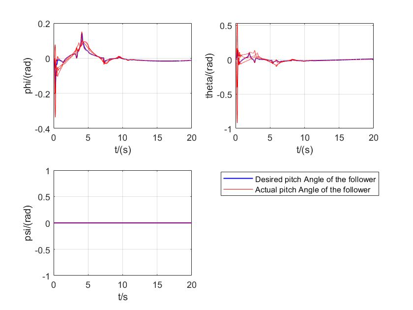
Figure 4. (a): Variation of attitude angles over time. (b): Variation of angular velocities over time.
Fig. 4(a) shows the variation of attitude angles over time. It can be observed that all quadcopters can quickly and accurately track the desired attitude of the leader. Initially, the followers adjust their attitudes rapidly to follow the leader and then maintain synchronization steadily. Particularly, even when there are significant changes in yaw angle, the controller still maintains good tracking performance. Fig. 4(b) illustrates the changes in angular velocities. The results indicate that angular velocities exhibit large fluctuations initially but quickly stabilize and accurately follow the desired angular velocity changes. This demonstrates the controller's effectiveness in suppressing overshoot and oscillations. To quantitatively assess the control performance, we computed the root mean square error (RMSE) of attitude control. During the stable flight phase (t > 2s), the average RMSE is less than 0.01 radians, indicating very high control precision. Additionally, we analyzed the energy efficiency of the controller by integrating the control torque.
6. Conclusion
This study has designed and simulated a finite-time controller for multi-quadcopter UAV formation control. Simulation results demonstrate excellent performance of the proposed control strategy in both position and attitude control. In position control simulation, quadcopters can quickly form the desired formation and accurately track the leader's complex trajectory, with position errors converging to near-zero levels in a short time. The attitude control simulation shows that even in the face of complex attitude changes, the controller ensures high-precision attitude synchronization and tracking. Both controllers exhibit fast convergence, high precision, strong disturbance rejection, and good energy efficiency. These results not only validate the effectiveness of the designed controllers but also provide reliable theoretical foundation and technical support for coordinated control of multi-quadcopter systems in complex environments.
References
[1]. Sharma M, Sundaram S. A geometric control approach for multi-UAV cooperative payload transfer[J]. Nonlinear dynamics, 2023, 111(11):10077-10096.
[2]. Singha A, Ray A K, Samaddar A B. Leader-Follower Based Formation Controller Design for Quadrotor UAVs[J]. Transactions of the Indian National Academy of Engineering, 2022(1):7.
[3]. Li Q, Chen Y, Liang K. Predefined-time formation control of the quadrotor-UAV cluster' position system[J]. Applied mathematical modelling, 2023, 116:45-64.
[4]. Elmokadem T. Distributed Coverage Control of Quadrotor Multi-UAV Systems for Precision Agriculture[J]. IFAC-Papers Online, 2019, 52(30):251-256.
[5]. Saif A W A, Ataur-Rahman M, Elferik S, et al. Multi-Model Fuzzy Formation Control of UAV Quadrotors[J]. Intelligent Automation and Soft Computing, 2021, 27(3):817-834.
Cite this article
Gao,Y. (2024). Based on graph theory, design of distributed control system for multi-quadcopter UAVs. Applied and Computational Engineering,86,51-58.
Data availability
The datasets used and/or analyzed during the current study will be available from the authors upon reasonable request.
Disclaimer/Publisher's Note
The statements, opinions and data contained in all publications are solely those of the individual author(s) and contributor(s) and not of EWA Publishing and/or the editor(s). EWA Publishing and/or the editor(s) disclaim responsibility for any injury to people or property resulting from any ideas, methods, instructions or products referred to in the content.
About volume
Volume title: Proceedings of the 6th International Conference on Computing and Data Science
© 2024 by the author(s). Licensee EWA Publishing, Oxford, UK. This article is an open access article distributed under the terms and
conditions of the Creative Commons Attribution (CC BY) license. Authors who
publish this series agree to the following terms:
1. Authors retain copyright and grant the series right of first publication with the work simultaneously licensed under a Creative Commons
Attribution License that allows others to share the work with an acknowledgment of the work's authorship and initial publication in this
series.
2. Authors are able to enter into separate, additional contractual arrangements for the non-exclusive distribution of the series's published
version of the work (e.g., post it to an institutional repository or publish it in a book), with an acknowledgment of its initial
publication in this series.
3. Authors are permitted and encouraged to post their work online (e.g., in institutional repositories or on their website) prior to and
during the submission process, as it can lead to productive exchanges, as well as earlier and greater citation of published work (See
Open access policy for details).
References
[1]. Sharma M, Sundaram S. A geometric control approach for multi-UAV cooperative payload transfer[J]. Nonlinear dynamics, 2023, 111(11):10077-10096.
[2]. Singha A, Ray A K, Samaddar A B. Leader-Follower Based Formation Controller Design for Quadrotor UAVs[J]. Transactions of the Indian National Academy of Engineering, 2022(1):7.
[3]. Li Q, Chen Y, Liang K. Predefined-time formation control of the quadrotor-UAV cluster' position system[J]. Applied mathematical modelling, 2023, 116:45-64.
[4]. Elmokadem T. Distributed Coverage Control of Quadrotor Multi-UAV Systems for Precision Agriculture[J]. IFAC-Papers Online, 2019, 52(30):251-256.
[5]. Saif A W A, Ataur-Rahman M, Elferik S, et al. Multi-Model Fuzzy Formation Control of UAV Quadrotors[J]. Intelligent Automation and Soft Computing, 2021, 27(3):817-834.