


1. Introduction
From the ancient wooden buildings to the modern steel structure "Bird's Nest" of 2008 Beijing Olympic Games, truss structure has occupied an important position in the history of architecture. Whether it is a venue with a span of hundreds of metres or a periodic truss microstructure material, truss structure can be seen everywhere in all kinds of projects. With the advantages of large spanning capacity, fast construction speed, lively and novel structural form and the ability to highlight human artistic creativity, truss structures are widely used in various spans of architectural structures, steel truss bridges, and satellite bearing structures and other projects [1].In recent years, space structures have developed rapidly, and all the structures composed of tension and compression rods belong to the truss category. Large-scale space structures, such as large-scale net frames covering tens of thousands of square metres in a building, are required to be designed successfully at one time, and no negligence is allowed; in addition, the steel consumption of such structures is huge, even tens of thousands of tonnes, such as "Bird's Nest", which uses 42,000 tonnes of steel. However, although truss structures are widely used, their design and optimization still face many challenges.
On the one hand, it is necessary to study the analysis method of truss structure to analyze its load bearing capacity and seismic performance, so as to make it safer and more reliable; on the other hand, it is necessary to study the optimal design method of truss structure to find out the best fit between high reliability and low consumption, so as to make its structure more reasonable and to make the best use of the limited resources.
Optimal design of structure refers to the optimal design of engineering structure under the conditions of support and load according to the predetermined objectives, and its goal is to achieve the optimal performance of the structure with the least material or the lowest cost [2,3,4].According to the different design methods, truss structure optimisation is mainly divided into three categories: topology optimization, shape optimization and size optimization. In terms of truss topology and layout optimization, the Michell truss theory proposed by Michell in 1904 and the classical layout theory established by Prager in 1977 laid the theoretical foundation, while the substructure method proposed by Dorn et al. marked the real beginning of truss topology optimization [5-6]. In topology optimization based on the base structure, the optimized solution is essentially a subset of the given base structure, so the adoption of the base structure actually limits the range of the optimized solution from the very beginning, and the true optimal solution is probably not included in the range. Therefore, to eliminate the limitation of the base structure, some non-base structure methods for truss topology and layout optimization have appeared one after another, such as Giger et al. who used mathematical graph theory to model the truss structure parametrically and combined with genetic algorithm to realize truss topology optimization free from the base structure[7], and Mroz et al. who borrowed the biological growth rule to generate the optimal topology by starting from the base structure and adding rods continuously[8].
With the above background research, this paper proposes a different design method for the optimization of truss structure, which aims to optimize the truss structure from the basic model of the structure and the basic force mechanism, and this method is more concise, clearer and easier to understand than the mathematical model optimization. Firstly, this paper analyses the different types of trusses and how to choose them for different scenarios, then analyses and designs the trusses through the given examples, and finally concludes the scheme.
2. Introduction of truss
A truss is a lattice structure consisting of straight rods connected to each other at the ends to resist bending as a whole. As shown in Figure 1, the commonly used flat trusses are Warren, Pratt, Fink, and Vierendeel. Warren truss, Pratt truss, Fink truss, and Vierendeel truss have their own unique advantages. Warren truss is widely used in modern engineering due to its simple equilateral triangular structure and cost-effective material use. Pratt joist is a reliable choice for railway bridges and other structures because of its diagonal and vertical compression bar configuration, while Fink joist provides strong supporting capacity and stability with its overlapping and interlocking steel tube structure, which is especially suitable for large-span buildings. The Vierendeel truss, by eliminating diagonal members, transmits and resists bending moments and is particularly suitable for applications where building functions are limited. Each truss form has its own characteristics and is best chosen according to specific application scenarios and needs.
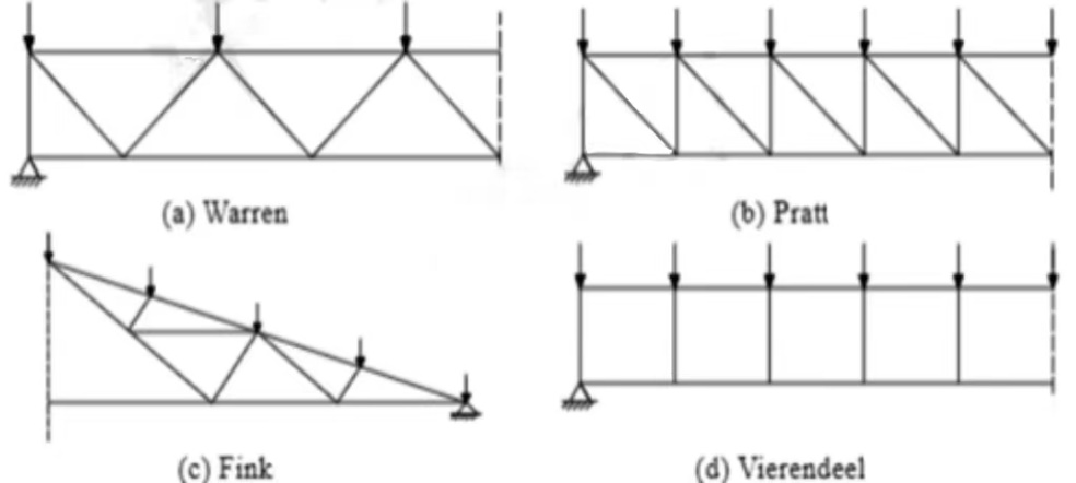
Figure 1. Types of Planar Trusses
Trusses can be divided according to the type of use, and different trusses have their own features and advantages. The main types include roof joist and bridge joist. Roof trusses are steel structure frames used to support roof loads. Common types include triangular trusses, parallelogram trusses, beam trusses and so on, which are generally composed of transverse members, vertical members and truss members with simple structure and good stability. Commonly used materials include steel, aluminium alloy, wood and so on, among which steel is the most widely used due to its high-strength and light-weight. Roof trusses are able to bear the pressure of the whole roof directly, support the weight of the roof and transfer it to the load-bearing walls of the house, as well as bear the additional weight exerted on the roof, such as snow, ice and equipment. In addition, it also serves to disperse wind and strengthen the structure. So it is widely used in the roof structure of all kinds of buildings, such as houses, factories, gymnasiums, etc.
As for bridge truss it is a bridge with truss as the main load-bearing member of the superstructure, which generally consists of main bridge frame, upper and lower horizontal longitudinal linkage, bridge portal and intermediate transverse bracing frames, and bridge deck system. The truss consists of chords (upper and lower chords) and webs (diagonal and vertical rods), which are also made of steel and aluminium alloy, but the specific selection depends on the requirements of the bridge, such as span and stiffness. As the main load-bearing member of a bridge, bridge truss bears the loads of vehicles and pedestrians on the bridge and transfers them to the foundation structure of the bridge, which is mainly used in bridge projects in the construction of highways, railways and waterways traffic, especially in the construction of large-span bridges.
3. Experimental results and discussion
3.1. Subjects of the study as well as the research formula and methodology
Design a truss, the length of the bridge is 85m, the distance from the bridge to the bottom of the bridge is 25m, the height of the bridge deck to the water surface is 15m, the complete space under the bridge is kept with the height of 5m and the width of 50m, and in order not to affect the landscape, the truss is not more than 8m higher than the horizon, and the load suffered by the bridge deck is 150KN/m, the materials used in the truss are all square cylindrical cross section (the wall thickness is 10mm), and it is necessary to consider the stability of the compression rod, and the material The allowable strength is 400Mpa, the elastic modulus is 200Gpa, and the minimum section size is 0.01m2. The designed truss is optimized to save the most material. As shown in Figure 1, the designed bridge should be under this condition
.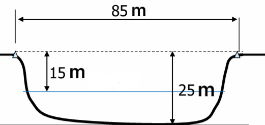
Figure 2. Scene where the truss is located
The force mechanism of the truss is used as the principle to optimize the design of the truss, as shown in Figure 2, to optimize the overall details of the truss.
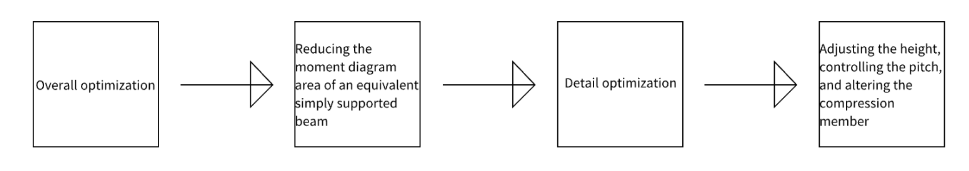
Figure 3. Optimization process for trusses
The axial forces corresponding to the individual bars were obtained using the structural mechanics solver and used to calculate the cross-sectional area.
The equation A = F/σ Euler's formula PE = π²EI/(μl)² was used [10].
This is obtained by deduction:Pcr=π²EI/l2=π²E*0.02d3/ 3l2
3.2. Optimization programme
The fundamental aspect of reducing material usage is to reduce the required surface area of the material, which can be done by reducing the bar pressure. Therefore, the optimization should be carried out with the aim of reducing the pressure on the members. This can be achieved in two ways: 1) from the overall design of the joist, the area of the moment diagram of the equivalent simply supported beam can be equated to the amount of pressure on the chord, so reducing the area of the moment diagram of the equivalent simply supported beam is an effective means of optimization. 2) from the details of the joist, the forces in the diagonal web and the uprights can be optimized. The shear force acts through the vertical component of the diagonal web, so the details can be optimized by adjusting the height of the joist and controlling the distance between the nodes. It is also possible to change the tensile and compressive situation of the rods by adjusting the direction of the diagonal web rods, and the design optimization should avoid the situation of too many compressed rods, because the compressed rods are facing the problem of instability, which will lead to the increase of the material consumption.
The design optimization of the truss was carried out on this topic, and the following solutions were designed and gradually optimized to the best solution
3.2.1. Option I
A basic Pratt truss was used and each node was equidistant from each other and of equal height (Figure 4). This solution is not optimized and is simple to design and construct, but requires a large amount of material.
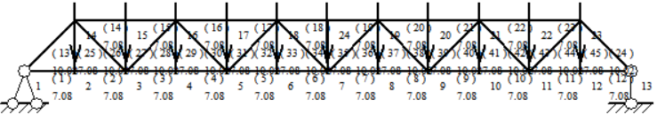
Figure 4. Basic pratt truss
3.2.2. Option II (making changes in height)
Initial optimization by changing the height of the riser, the higher the height of the riser, the lower the axial force on the upper and lower chords, the reduction in the cross-sectional area of the material required, the length of the diagonal web and the riser will increase, but the benefits outweigh the drawbacks (Figure 5). The programme through the optimization of the height of the details of the optimization, the original 7.08m increased to 8m, the design and construction of this program is simple, the required material compared to the programme has been reduced(Table 1).
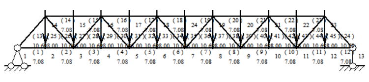
Figure 5. Basic pratt truss after height modification
Table 1. Comparison of total volume between Option 1 and Option 2
Option | Maximum axial force on bar (KN) | Total volume of material required (m³) |
Option 1 | 19125 | 7.209 |
Option 2 | 16933 | 6.548 |
3.2.3. Option III (with overall optimization)
(1)The area of the equivalent simply supported girder moment diagram is reduced by adding an abutment 25m long, the height is maintained at 8m, the pitch of the left section is 6.875m and the pitch of the right section is 7.5m. as shown in Figure 6. The construction of this truss is slightly more difficult but the material required is reduced considerably as compared to scheme I and scheme II.
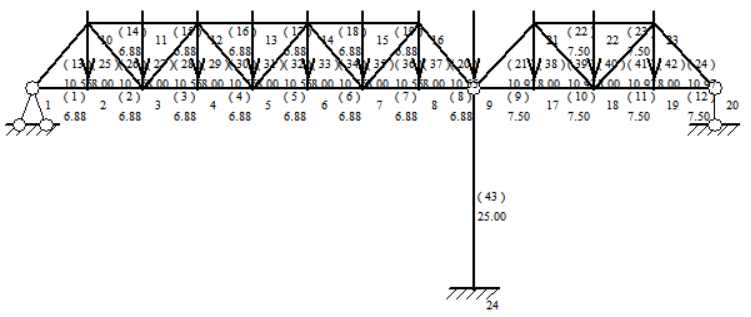
Figure 6. Truss after adding 1 post
(2)Adding two piers of 25m length reduces the area of the equivalent simply supported beam moment diagram, the truss height is kept at 8m, the pitch of the left part and the right part are equal to 7.5m, and the pitch of the middle part is 6.875m. as shown in Figure 7. the truss is more difficult to construct, and the required material is relatively less.
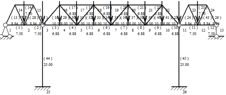
Figure 7. Truss after adding 2 columns
(3)On the basis of adding a 25m abutment to increase the node to change the area of the equivalent simply supported beam moment diagram, the left fixed end restraint to the column node is 6.88m and the right end of the column is 7.5m. the height of the truss is 8m. as shown in Figure 8. this truss requires less material and is slightly more difficult to construct.
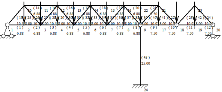
Figure 8. Adding a truss with 1 column and then adding the nodes
Comparing the area of the equivalent simply supported beam bending moment diagrams, the area of solution III (3) is the minimum and is the best solution after overall optimization(Table 2).
Table 2. Comparison of total volume diagrams for Option 2 and Option 3
Option | Maximum axial force on bar (KN) | Total volume of material required (m³) |
Option 2 | 16933 | 6.548 |
Option 3(1) | 7090 | 3.066 |
Option 3(2) | 7090 | 3.050 |
Option 3(3) | 8114 | 2.873 |
3.2.4. Option 4 (optimizing details).
This solution optimizes and updates solution III (3) by changing the position and spacing of the intermediate diagonal web, the pitch from the left fixed end restraint to the columns is 9.17m, the pitch from the columns to the right fixed end restraint is 7.5m, and the height of the trusses is kept at 8m. as shown in Figure 9. This solution is optimal in terms of material saving, but the construction difficulty is a little higher(Table 3).
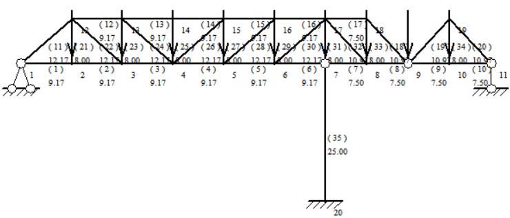
Figure 9. Truss after detail optimization for option three
Table 3. Comparison of the total volume of each scheme after stepwise optimization
Option | Maximum axial force on bar (KN) | Total volume of material required (m³) |
Option 1 | 19125 | 7.209 |
Option 2 | 16933 | 6.548 |
Option 3(3) | 8114 | 2.873 |
Option 4 | 8114 | 2.688 |
Comparing the above data, Option 4 has a small maximum axial force at the rod end and requires the smallest total volume of material, making it the optimal solution in terms of material savings.
4. Conclusion
This paper applies the force mechanism of truss structure to design and optimize the truss through overall optimization and detail optimization. The design optimization of truss is a comprehensive process which involves various considerations. In the design optimization of truss, the height of truss is considered firstly, and the height of truss is increased as much as possible under the premise that the height is permitted; the area of equivalent simply supported beams is considered in the design of truss, and it is reduced reasonably, so as to design the best model of truss; finally, the inclination angle of beams is adjusted, and the inclination is controlled at a reasonable angle, so as to avoid the wastage of materials and reduce the cost of project. Choosing more suitable materials can effectively reduce the usage of materials and improve the performance of the whole truss. With the continuous development of science and technology, there are many ways and methods to optimize truss design, such as finite element analysis by ANSYS software, topology optimization of continuum structure and so on. The optimization of truss design is important to improve structural efficiency, reduce cost, reduce weight, improve aesthetics, increase sustainability and cope with complex loads and environmental conditions.
References
[1]. Yu S & Tang H 2023 J. Northwestern Polytechnical University Social Sciences 41 04 722-731
[2]. Xu J & Lv X 2015 J. Building Structures 36 03 127-132
[3]. Zhao Z Wu J & Liu H 2020 J. Building Structures 41 02 125-133
[4]. Wu Y Hu Q & Li Q 2016 J. Building Structures 37 06 46-52
[5]. Jiang D & Zhang Z 2006 Advances in Science and Technology of Water Resources 02 81-86
[6]. Michell A G M 1904 The limits of economy of materials in frame structures Philosophical Magazine Series 6
[7]. Giger M & Ermanni P 2006 Evolutionary truss topology optimization using a graph-based parameterization concept Structural & Multidisciplinary Optimization 32 4 313-326
[8]. Mróz Z & Bojczuk D 2003 Finite topology variations in optimal design of structures Structural & Multidisciplinary Optimization 25 3 153-173
[9]. Shen C 2007 Harbin Institute of Technology
[10]. Li K 2003 Journal of Hunan Institute of Science and Technology 04 66-67+80
Cite this article
Feng,J. (2024). Design optimization of trusses based on structural mechanics mechanisms. Applied and Computational Engineering,72,238-244.
Data availability
The datasets used and/or analyzed during the current study will be available from the authors upon reasonable request.
Disclaimer/Publisher's Note
The statements, opinions and data contained in all publications are solely those of the individual author(s) and contributor(s) and not of EWA Publishing and/or the editor(s). EWA Publishing and/or the editor(s) disclaim responsibility for any injury to people or property resulting from any ideas, methods, instructions or products referred to in the content.
About volume
Volume title: Proceedings of the 2nd International Conference on Functional Materials and Civil Engineering
© 2024 by the author(s). Licensee EWA Publishing, Oxford, UK. This article is an open access article distributed under the terms and
conditions of the Creative Commons Attribution (CC BY) license. Authors who
publish this series agree to the following terms:
1. Authors retain copyright and grant the series right of first publication with the work simultaneously licensed under a Creative Commons
Attribution License that allows others to share the work with an acknowledgment of the work's authorship and initial publication in this
series.
2. Authors are able to enter into separate, additional contractual arrangements for the non-exclusive distribution of the series's published
version of the work (e.g., post it to an institutional repository or publish it in a book), with an acknowledgment of its initial
publication in this series.
3. Authors are permitted and encouraged to post their work online (e.g., in institutional repositories or on their website) prior to and
during the submission process, as it can lead to productive exchanges, as well as earlier and greater citation of published work (See
Open access policy for details).
References
[1]. Yu S & Tang H 2023 J. Northwestern Polytechnical University Social Sciences 41 04 722-731
[2]. Xu J & Lv X 2015 J. Building Structures 36 03 127-132
[3]. Zhao Z Wu J & Liu H 2020 J. Building Structures 41 02 125-133
[4]. Wu Y Hu Q & Li Q 2016 J. Building Structures 37 06 46-52
[5]. Jiang D & Zhang Z 2006 Advances in Science and Technology of Water Resources 02 81-86
[6]. Michell A G M 1904 The limits of economy of materials in frame structures Philosophical Magazine Series 6
[7]. Giger M & Ermanni P 2006 Evolutionary truss topology optimization using a graph-based parameterization concept Structural & Multidisciplinary Optimization 32 4 313-326
[8]. Mróz Z & Bojczuk D 2003 Finite topology variations in optimal design of structures Structural & Multidisciplinary Optimization 25 3 153-173
[9]. Shen C 2007 Harbin Institute of Technology
[10]. Li K 2003 Journal of Hunan Institute of Science and Technology 04 66-67+80