


1. Introduction
In industrial production, different local temperatures in the production process of parts have different cooling requirements. Parts need to be tested locally, using the most appropriate fan speed to achieve the best cooling effect on the parts. This design improves the traditional shifting fan to achieve the above effect [1].
In this design, Arduino will be used for programming design, and sensor technology will be used to detect the local current environment where the fan is located.
Therefore, Arduino is used for design because it has three characteristics. The Arduino IDE runs on three main operating systems: Windows, Macintosh, and Linux. Second, Arduino is simple and clear. Arduino IDE is developed based on processing ideas, which is easy to master and flexible enough to quickly meet the current design needs. Third, it is open, Arduino hardware schematics, block diagrams, IDE software, and core library files are open source, in the scope of the open-source protocol can be arbitrarily modified the original design and the corresponding code, so that programming is convenient, simple, and clear.
The use of temperature sensors to achieve that when the temperature is too low, the fan speed is very low or does not work, so that it can avoid the energy waste caused by the high-speed operation of the motor in this case and the defects that may cause the local temperature of the parts to be too low, which is more reasonable than the traditional cooling fan [2]. In addition, this design uses an infrared sensor. When there is no part in front of the fan, the fan does not work. This prevents the fan from idling and saves a certain amount of electricity. It not only controls the cost but also achieves the effect of environmental protection [3].
2. Design method and process
2.1. Select element
This design uses a DS18B20 temperature sensor. The sensor has a single-wire interface, requiring only one port wire to communicate with multiple points, simplifying distributed temperature sensing applications. It does not require external components and can be powered by a data bus, making the designed product small and easy to set up and distribute parts.
The infrared sensor selected in this design is SEN0018 from DFROBOT, which is a simple and easy-to-use motion sensor. Turn on the power and wait 1-2 seconds for the sensor to get a snapshot of the still room. If there is any movement after this period, it will input the digital signal "1". If not, enter the digital signal "0".
The selected infrared sensor is worth noting the following specifications. Its type is a digital sensor. The available supply voltage is 3~ 5v, and the operating current is 50μΑ. It can maintain normal operation at the temperature of 0℃~+70℃. The maximum output level is 4v and the minimum is 0.4v. The detection Angle is 110 degrees, and the detection distance is 7m. Its size is:28mm × 36mm, weighing 25g[4].
The 5161AS digital tube used in this design is a common cathode digital tube. Each digital tube consists of 8 LEDs, pins a to g display the numbers, dp display the points. Our design controls four digital tubes to display temperature numbers.
The a, b, c, d, e, f, g pins of the common cathode nixie control various parts of the digital display, and the dp pins control the decimal point. In an ordinary cathode nixie, connect the upper and lower COM pins to the low level, and then display the corresponding number by connecting the high level of the a, b, c, d, e, f, and g pins. The working principle is shown in Figure 1.
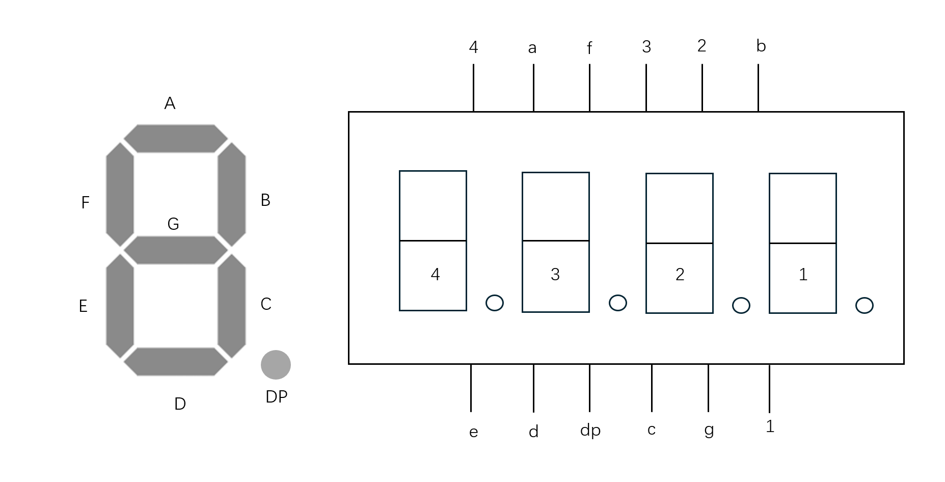
Figure 1. The 5161AS digital tube.
In ordinary cathode nixie: low level is 0, high level is 1. When COM is connected to a low level and nixie is connected to a high level, the corresponding digital portion lights up. In summary, when the value is 1, the digital tube lights up; When the value is 0, the nixie tube is not bright.
Table 1. Common cathode digital tube truth table[5].
Common cathode digital tube truth table | ||||||||||
COM | dp | g | f | e | d | c | b | a | display | |
0 | 0 | 0 | 1 | 1 | 1 | 1 | 1 | 1 | 0 | |
0 | 0 | 0 | 0 | 0 | 0 | 1 | 1 | 0 | 1(right) | |
0 | 0 | 0 | 1 | 1 | 0 | 0 | 0 | 0 | 1(left) | |
0 | 0 | 1 | 0 | 1 | 1 | 0 | 1 | 1 | 2 | |
0 | 0 | 1 | 0 | 0 | 1 | 1 | 1 | 1 | 3 | |
0 | 0 | 1 | 1 | 0 | 0 | 1 | 1 | 0 | 4 | |
0 | 0 | 1 | 1 | 0 | 1 | 1 | 0 | 1 | 5 | |
0 | 0 | 1 | 1 | 1 | 1 | 1 | 0 | 1 | 6 | |
0 | 0 | 0 | 0 | 0 | 0 | 1 | 1 | 1 | 7 | |
0 | 0 | 1 | 1 | 1 | 1 | 1 | 1 | 1 | 8 | |
0 | 0 | 1 | 1 | 0 | 1 | 1 | 1 | 1 | 9 | |
Therefore, the case for numbers 0-9 is shown in Table 1. For example, when the required number is 0, the low level is connected in the common end, the high level is connected in pins a, b, c, d, e, and f, respectively, and the low level is connected in pins g and dp, and the number displayed on the common cathode nixie is 0.
The motor selected for this project is Micro 130 motor with a size of 20*15*25 (mm). The nominal voltage range of the motor is 3-5V and the nominal current range is 0.35 ~ 0.4A. The no-load current of the test motor is about 0.19A, and the speed of the motor under this current is 140 RPM.
2.2. A circuit used to control the speed of a motor
The project design involves using multiple sensors to detect the surrounding environment and send feedback to the Arduino Uno3 board to drive the motor in the circuit. To drive the motor, the circuit design is included in the scheme design. The circuit diagram is shown in Figure 2.

Figure 2. The circuit use to control the speed of motor
The circuit is mainly composed of DC motor, 1kΩ resistor and MOSFET transistor. The transistor model is K3703, and the model is NMOS.
In a circuit, a transistor acts as a switch to control the on-off state of the circuit. The working principle of a transistor is as follows: a transistor has three characteristic pins, drain, gate and source, as shown in Figure 4. When the voltage between the gate and the source is greater than the threshold voltage (Vgs > Vt), the conductive channel opens and the circuit is "on", and vice versa. In addition, modifying the voltage between the gate and the source will change the current through the drain, which can further control the speed of the motor. Equation (1) explains this relationship.
\( {I_{d}}={k({V_{gs}}-{V_{t}})^{2}} \) (1)
Where Id is drain current, k is the correlation coefficient of device parameters, Vgs is the voltage between gate and source, and Vt is the threshold voltage [6].
2.3. General circuit diagram
The total circuit diagram is shown in Figure 3. A0-A5, 4-9 pins of Arduino Uno3 broad are used to control the nixie tube. To protect the circuit, a 220Ω resistor is connected between the pin and the pin used to control each digit.
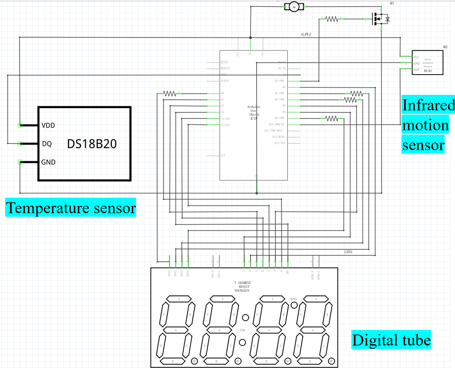
Figure 3. The general circuit
3. Design procedure
The general process of designing the system is shown in Figure 4. Infrared sensors detect the presence of parts in front. If not, the digital signal "0" is entered, the entire system remains stationary for 10 seconds, and then the sensor detects again. If yes, enter the digital signal "1". The temperature sensor will start working. It detects the local temperature of the part and feeds it into the computer. The computer will use this code to output the temperature in the serial monitor. The temperature is then read, and a code is used to control the speed of the motor. At the same time, the design also uses the code to display the temperature on the digital tube.
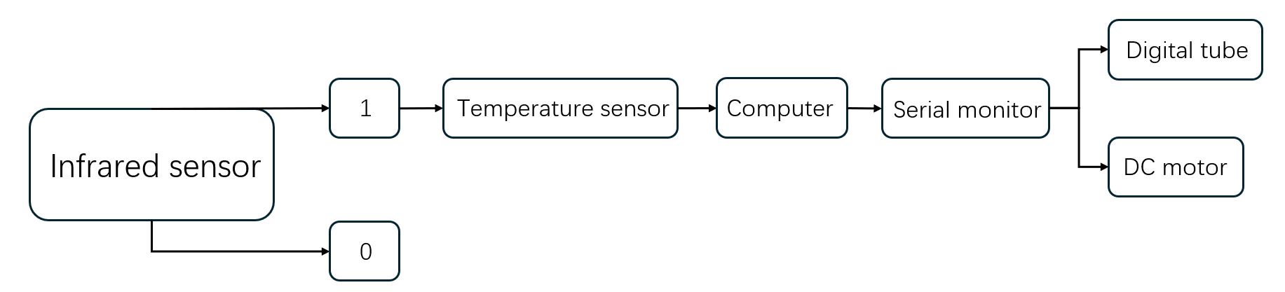
Figure 4. The general procedure
3.1. Speed of motor
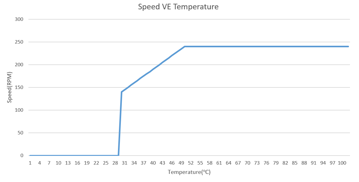
Figure 5. The speed of the motor vs temperature
In this design, the speed of the motor is designed to be controlled by the temperature signal transmitted by the temperature sensor. The relationship between speed and temperature is shown in Figure 5. For example, if 30 ° C is the appropriate temperature for parts production when the temperature is lower than 30 ° C. The motor will stop operating, because the temperature at this time basically reaches the cooling demand, so the radiator stops.
When the temperature of the part reaches 30℃, the speed is 140rpm, which is the speed of the motor under no-load current. When the temperature of the part is between 30 and 50 ° C, the relationship between speed and time is a one-time function. When the temperature is 50 ° C, the speed is 240 RPM, which is the maximum speed of the motor.
4. Research results and discussions
The fan in this design has the following characteristics: First, due to the infrared sensor, the fan will only work when there are parts in front of the fan. Next, because the temperature sensor is set, the fan will set the current fan speed according to the local temperature of the part to achieve the best cooling effect. Finally, the fan does not have gear adjustment, and the selected motor is a stepless speed change, so the fan speed change is a linear transformation, which meets the requirements of local cooling.
4.1. The impact and significance of the study
The continuously variable speed fan designed in this research institute first expands the design field of Arduino technology and uses simple programming design technology to complete the product design with practical significance.
In addition, sensor technology is cleverly integrated into the design. This can be used to detect the working condition of parts in industrial production. In the future, local parts and whole parts can be inspected and adjusted. The whole design has reference significance for safety production and product quality improvement.
4.2. Future research
4.2.1. Accuracy of temperature sensor
In the process of data processing, the difficulty that may be encountered in the future is that the temperature of the temperature sensor is the data read by the float function, and the data read by the digital tube is the data read by the int function. The two modification methods are different, resulting in errors in the temperature of the data read after modification, which affects the data processing. In future studies, it is possible to consider whether the selection of temperature sensors can be changed to improve the temperature accuracy, to further improve the change accuracy of fan speed.
4.2.2. Display of ordinary cathode digital tube
In the process of reading the data, the display of the ordinary cathode nixie tube will flicker, which is not conducive to reading the data, and may cause discomfort to the workers' eyes when reading the data. In future studies, it may be considered whether to change the temperature display mode and whether the data can be transmitted directly to the computer, rather than using the cathode nixie display[7].
4.2.3. Rated power of motor
In this design, the rated power of the selected motor is small and easy to damage. Therefore, it cannot be applied to high temperature conditions. In the future research, it can be considered to replace the stepless motor with higher power and stronger high temperature resistance [8].
4.2.4. Functional components that can continue to be added.
In future studies, filters can be added to eliminate noise and interference, combined with the Kalman filter code in Arduino to reduce possible errors in real-world operations[9]. In addition, the liquid crystal display (LCD) is also a functional component that can be added, the LCD will not flicker, increase the
Footnotes should be avoided whenever possible. If required they should be used only for brief notes that do not fit conveniently into the text[10].
5. Conclusion
In this study, Arduino technology is used to design a stepless fan that can adjust the speed according to the current temperature and is used in industrial production. First of all, the article starts with why the Arduino technology is used and expounds the advantages and characteristics of Arduino technology. This paper discusses the design concept, the design method, the component information, and the design circuit diagram. The connection mode and operation principle of each component and the design idea of fan speed are also explained in detail. The paper also adds the circuit elements that can be added in the future, which is also the improvement space of the product in the future. In future product applications, the product can also be micro-improved to broaden the application scenario and achieve integration and application under more complex working conditions. Or add more electronic components to help it complete more complex temperature control and monitoring, thereby improving the adjustment accuracy and application breadth of the product. This will lead to higher economic benefits and contribute to society.
References
[1]. Cai R 2012 The principle and application of Arduino Electronic Design Engineering 20(16) p 155-157
[2]. Holloway P R Subrahmayan R Sheehan G S 2001 Linearized temperature sensor US US06183131B2
[3]. Horn S B 2002 Infrared sensor system technique US US6335526B1
[4]. Kulkarni V Wright K M Beifus B L Becerra R C & Archer W A 2007 Method and apparatus to control a variable speed motor US US2007085498A1
[5]. Liu W C 2014 The invention relates to a common cathode and common anode composite package digital tube and a control method thereof
[6]. Umberto M 1980 Circuit arrangement for controlling an according to the chopper principle operating transistor DE3010784A1
[7]. Machover C 1973 Displays Electro-Optics
[8]. Introduction 4 BEGA – MOTOR/GENERATOR OPERATION AT UNITY POWER FACTOR
[9]. Hong J 2011 Nine advanced rf/microwave filters John Wiley Sons Inc p 261-333
[10]. Wang P H 2004 Pellucid LCD and fabrication method of same US US2004075790A.
Cite this article
Sun,Y. (2024). Design of locally cooled step-less fan for industrial use using Arduino programming. Applied and Computational Engineering,81,1-7.
Data availability
The datasets used and/or analyzed during the current study will be available from the authors upon reasonable request.
Disclaimer/Publisher's Note
The statements, opinions and data contained in all publications are solely those of the individual author(s) and contributor(s) and not of EWA Publishing and/or the editor(s). EWA Publishing and/or the editor(s) disclaim responsibility for any injury to people or property resulting from any ideas, methods, instructions or products referred to in the content.
About volume
Volume title: Proceedings of the 2nd International Conference on Machine Learning and Automation
© 2024 by the author(s). Licensee EWA Publishing, Oxford, UK. This article is an open access article distributed under the terms and
conditions of the Creative Commons Attribution (CC BY) license. Authors who
publish this series agree to the following terms:
1. Authors retain copyright and grant the series right of first publication with the work simultaneously licensed under a Creative Commons
Attribution License that allows others to share the work with an acknowledgment of the work's authorship and initial publication in this
series.
2. Authors are able to enter into separate, additional contractual arrangements for the non-exclusive distribution of the series's published
version of the work (e.g., post it to an institutional repository or publish it in a book), with an acknowledgment of its initial
publication in this series.
3. Authors are permitted and encouraged to post their work online (e.g., in institutional repositories or on their website) prior to and
during the submission process, as it can lead to productive exchanges, as well as earlier and greater citation of published work (See
Open access policy for details).
References
[1]. Cai R 2012 The principle and application of Arduino Electronic Design Engineering 20(16) p 155-157
[2]. Holloway P R Subrahmayan R Sheehan G S 2001 Linearized temperature sensor US US06183131B2
[3]. Horn S B 2002 Infrared sensor system technique US US6335526B1
[4]. Kulkarni V Wright K M Beifus B L Becerra R C & Archer W A 2007 Method and apparatus to control a variable speed motor US US2007085498A1
[5]. Liu W C 2014 The invention relates to a common cathode and common anode composite package digital tube and a control method thereof
[6]. Umberto M 1980 Circuit arrangement for controlling an according to the chopper principle operating transistor DE3010784A1
[7]. Machover C 1973 Displays Electro-Optics
[8]. Introduction 4 BEGA – MOTOR/GENERATOR OPERATION AT UNITY POWER FACTOR
[9]. Hong J 2011 Nine advanced rf/microwave filters John Wiley Sons Inc p 261-333
[10]. Wang P H 2004 Pellucid LCD and fabrication method of same US US2004075790A.