


1. Introduction
The PID controller has a long history in automatic control. James Watt developed the steam engine and governor in 1769, and these inventions were recognized as the first implementation of a negative feedback device [1–3]. A theoretical analysis for the derivative of error was offered by Nicolas Minorsky [2]. The development of the first PID controller was pioneered by Elmer Sperry in 1911, specifically for the US Navy [3, 4]. The core PID algorithm boasts several advantages, including excellent robustness, straightforward adjustment, a simple algorithm, and high stability. These features have made the PID control method and its underlying technology one of the most widely adopted and mature control technologies in the industrial sector. Nonetheless, the PID control system encounters challenges in maintaining its efficiency when confronted with nonlinear systems and broader setpoint ranges, frequently leading to overshoot and suboptimal control performance. Researchers have devised the Fuzzy-PID controller to mitigate these issues, specifically tailored to function efficiently with nonlinear systems. The Fuzzy PID control system has been widely used and recognized in industrial control due to its strong robustness, good adaptability, high control accuracy, simple, stable, reliable structure, and wide applicability. For a BLDC motor, nonlinearity exists when the load is large, and it is possible to fail to activate, so studying fuzzy PID control is of great significance in practical circumstances.
In this paper, a math model of a DC motor is established, and a traditional PID controller and fuzzy PID controller are applied to control it through Falstad and Simulink. Compared with previous research, this paper uses operational amplifiers to model the DC motor, Simulink is also used to verify the rationality of the model, and additional analyzes in the frequency domain have been done. In order to improve the system performance further, a lead lag compensator must be added properly. Through this study, the necessity of a fuzzy PID controller is verified.
2. The model construction and control analysis
2.1. Math modeling of DC motor
In order to derive the math model of DC motor, we can apply several equations:
The voltage equilibrium gives:
\( {u_{a}}={e_{a}}+{R_{a}}{i_{a}}+{L_{a}}\frac{ⅆ{i_{a}}}{dt} \) , where \( {e_{a}}={k_{e}}ω \) . (1)
The torque equilibrium gives:
\( {T_{em}}={T_{0}}+{T_{L}}+J\frac{ⅆω}{ⅆt} \) , where \( {T_{em}}={k_{t}}{i_{a}} \) . (2)
Here \( {e_{a}} \) is back electromotive force, \( {u_{a}} \) is the input voltage, \( {k_{e}} \) is the back emf coefficient, \( ω \) is the rotation speed, \( {T_{em}} \) is the electromagnetic torque, \( {T_{0}} \) is no-load torque, \( {T_{L}} \) is the load’s torque, \( J \) is the moment of inertia, \( {k_{t}} \) is the torque coefficient, R is the armature resistance, and L is the armature inductance.
Substitution gives:
\( J\frac{{d^{2}}θ}{d_{t}^{2}}+\frac{{k_{t}}{k_{e}}}{{R_{a}}+s{L_{a}}}\frac{ⅆθ}{dt}=\frac{{u_{a}}{k_{t}}}{{R_{a}}+s{L_{a}}}-{T_{0}}-{T_{L}} \) (3)
Assuming \( {L_{a}} \) , \( {T_{0}} \) , \( {T_{L}} \) terms are small, and thus doing Laplace transformation, the transfer function becomes:
\( \frac{θ}{{U_{a}}}=\frac{\frac{{k_{t}}}{{R_{a}}}}{s(J{R_{a}}s+{k_{t}}{k_{e}})} \) (4)
Looking up the datasheet of 2338 0006s to determine the parameters:
\( \frac{3}{s(0.1s+1)} \) (5)
2.2. Realizing PID control of DC motor through Falstad
PID control is a control method commonly used in the production process, and it has been widely used in electromechanical, metallurgical, mechanical, chemical and other industries.
The PID controller, renowned for its versatility and efficiency, is a prevalent closed-loop control system utilized across diverse applications. It leverages feedback from sensors to modulate the process variable, ensuring it maintains proximity to the predefined setpoint [5].
In PID controller, P, I and D represents proportion, integral and differential. The common PID controller formula could be written as:
\( {K_{p}}ⅇ(t)+{K_{i}}∫ⅇ(t)ⅆt+{K_{d}}\frac{ⅆⅇ(t)}{ⅆt}=u(t) \) (6)
However, this form is of little help to build our model, so do the Laplace transformation:
\( {K_{P}}+\frac{{K_{i}}}{s}+{K_{d}}s = \frac{U(s)}{E(s)} \) (7)
In order to realize the model of a DC motor by using op-amps, a parallel spaced resistor and capacitor are required to be placed at the feedback position, besides, a simple integrator is also required to connect to it in series.
To implement PID control, just construct op-amps to reach the desired transfer function. For PI, a resistor and a capacitor must be placed at the feedback position while for PD, just use a resistor and an inductor. The transfer functions could be deducted:
PI: \( \frac{{R_{2}}cs+1}{{R_{1}}cs} \) , PD: \( \frac{L}{{R_{1}}}s+\frac{{R_{2}}}{{R_{1}}} \) (8)
Comparing with those transfer functions in theory:
PI: \( {K_{P}}+\frac{{K_{i}}}{s} \) , PD: \( {K_{P}}+{K_{d}}s \) (9)
The parameters of electrical elements and corresponding \( {K_{P}} \) , \( {K_{i}} \) and \( {K_{d}} \) could be determined successively. Observing the root locus of the whole system, the time constants of PI and PD could be determined to reach an optimum response. After plotting several loot loci for the pole position introduced by PI controller, -0.1 is an ideal pole position with a relatively fast response and a small oscillation. As for the zero introduced by the PD controller, zero at -15 is enough to reach a fast response with little oscillation. Adjusting Kp for several times, an ideal step response could be attained. The values of elements are chosen properly as follows:
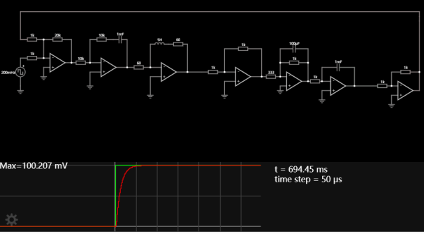
Figure 1. Using PID controller to control the position of BLDC motor model
As can be seen, the step response is quite ideal with a small rise time and overshoot. After calculation, Kp = 28.187, Ki = 2.8, Kd = 1.87
3. The model control analysis
3.1. Using Simulink to establish fuzzy PID control
Establishing a fuzzy PID controller is based on traditional PID controller mentioned above while the values of Kp, Ki, Kd could be determined through a set of fuzzy deduction rules [6]. The DC motor fuzzy PID controller in this paper is a two-input and three-output structure, the input of the fuzzy controller is the deviation e and the derivative of deviation ec. The output is the PID controller parameter correction ΔKp, ΔKi, ΔKd. When the control system is running [7], the input quantities e and ec are fuzzified, fuzzy inferenced and de-fuzzified, and the online correction ΔKp, ΔKi and ΔKd are respectively input into the PID controller, so that the DC motor can adjust Kp, Ki, and Kd in real time. [8] This could ensure that the system reaches the best response state and the DC motor has good static and dynamic performance [9].
The fuzzy PID controller outputs Kp, Ki and Kd in the following relationship:
\( \begin{cases} \begin{array}{c} {K_{p}}={K_{Po}}+Δ{K_{p}} \\ {K_{i}}={K_{{i_{0}}}}+Δ{K_{i}} \\ {K_{ⅆ}}={K_{{d_{0}}}}+Δ{K_{d}} \end{array} \end{cases} \) (10)
Fuzzy control rules constitute a collection of fuzzy conditional statements that are derived from the expertise of professionals and the skills of operators, serving as the pivotal step in the process of fuzzy reasoning. To reach an ideal performance, reasonable control rules ought to be formulated. After referring to several relevant literatures, the fuzzy subsets of all variables are determined to be: {NB, NM, NS, ZO, PS, PM, PB}, where P stands for positive, N is for negative, S is for small, M is for middle, B is for big, ZO represents zero. The membership function is chosen as trimf, the Mamdani method is chosen as fuzzy reasoning rule, domain of inputs and outputs are [-3, 3]. The fuzzy rule table is determined by referring to literature.
The fuzzy PID and traditional PID are constructed as follows:
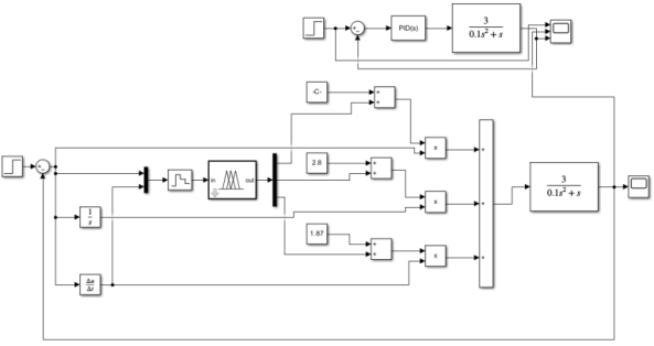
Figure 2. The establishment of fuzzy PID controller and traditional PID controller using Simulink
Entering the Kp, Ki and Kd we got before as initial values, the step responses are shown:
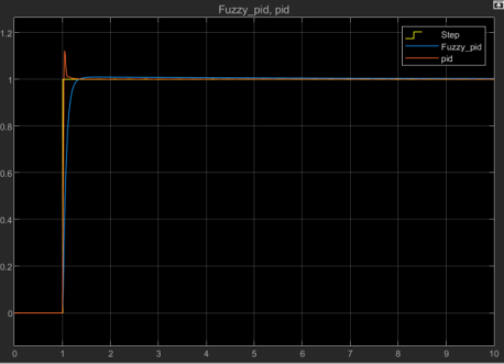
Figure 3. The comparison of step response of both PID controller
As can be seen, the traditional PID result using Simulink has a small overshoot value, which is different from the simulation result of Falstad. The fuzzy PID controller successfully reduced the overshoot to a quite small value although the rise time has been slightly enlarged. The export data is shown below:
Table 1. The time domain parameters of both PID controller exported from Simulink
Time domain parameters | Traditional PID controller | Fuzzy PID controller |
Rise time (s) | 1.014394 | 1.047218 |
Settling time (s) | 1.089123 | 1.2 |
Peak overshoot (%) | 12.3204 | 0.9821 |
Peak time (s) | 1.047218 | 1.66935 |
The traditional PID has a rise time of 1.014394s, a settling time of 1.089123s and an overshoot of 12.3204%, while the fuzzy PID has a rise time of 1.047218s, a settling time of 1.2s and an overshoot of 0.9821%. The traditional PID rises faster and reaches a steady state faster, but the overshoot value is quite large. The fuzzy PID slightly slower and reaches the steady state slower, but the overshoot is small. To conclude, although the traditional PID controller has a faster response, the fuzzy PID provides an overshoot value of 0.9821%, which could be ignored relative to 12.3204% of traditional PID. In practical applications, the small difference in response time has little effect on the performance, but the large overshoot matters. To conclude, the fuzzy PID controller provides a better response performance than the traditional PID controller. It does not require the input parameters to be too precise to reach a good response.
3.2. Frequency-domain analysis of the control results and further optimization
Lead-lag compensators are common control elements which is used to achieve a desired performance of the system [10]. The general transfer function of a lead lag compensator is:
\( \frac{(s+{Z_{1}})(s+{Z_{2}})}{(s+{P_{1}})(s+{P_{2}})} \) (11)
The lead-lag compensator’s lead and lag components are crucial in introducing phase lead to bolster stability and minimize steady-state error, ultimately enhancing the transient response [11].
The Bode plot of our traditional control system shows that the phase margin is up to 88.4 degrees when frequency is 75.3 rad/s, which is too large. Besides, the phase is at -180 degrees at low frequencies, which means serious noise amplification exists. To make the circumstance better, lead lag compensators are chosen here.
\( \frac{s}{s+0.8} \frac{s+120}{s+60} \) (12)
After the addition of lead compensator \( \frac{s}{s+0.8} \) , the low frequency phase is changed to -90 degrees, which indicates that it does not amplify the noise. However, the phase margin is 89 degrees here, which is too large to perform well. Looking up literatures, the phase margin should be at least 45 degrees, 60 degrees is the best [12].
Applying the lag compensator \( \frac{s+120}{s+60} \) to decrease the phase margin, the result is shown:
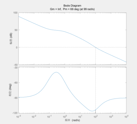
Figure 4. The Bode plot of whole system with lead-lag controller
The phase margin is reduced to 66 degrees, which satisfies the design criterion.
4. Conclusion
In this paper, a DC motor was modeled in order to do PID control, the advantages and disadvantages of traditional PID controller and fuzzy PID controller were compared and analyzed, and a conclusion that fuzzy PID controller performs better than the traditional PID controller was reached. The control performance of the system was further optimized using a lead-lad compensator in the frequency domain. After analysing of voltage and torque equilibrium, we deduced the math model of a transfer function of a DC motor and the parameters were determined by looking up the datasheet. (Voltage in angle out) Then, the traditional PID simulation based on the operational amplifier is constructed using Falstad. The model of the DC motor and PID controller were established by analyzing transfer functions while the value of Kp, Ki, Kd were determined by observing the root locus and response curve generated by Matlab and Falstad.
Next, Simulink was used to realize the fuzzy PID control and compare with the traditional PID control result. The fuzzy subsets and fuzzy rules were established by looking up literatures. After the simulation, it can be observed that although the traditional PID controller has a slightly faster response, the fuzzy PID controller provides an overshoot value of 0.9821%, which is optimal. Finally, the control result was analyzed in frequency domain. A lead-lag compensator was added to improve the performance since the original phase margin was too large and there was a risk of amplifying noise. Because of the limitation of objective factors, there is a lack of hardware for actual wiring, and it can be carried out after the conditions are improved. In the future, other nonlinear control methods will be simulated, and further studies will be constructed.
References
[1]. Kang C-G (2016) Origin of stability analysis: “on governors” [historical perspectives]. IEEE Control Syst Mag 36(5):77–88
[2]. Medaglia JD (2019) Clarifying cognitive control and the control lable connectome. Wiley Interdiscip Rev Cognit Sci 10(1):1471
[3]. Aström KJ, Kumar PR (2014) Control: a perspective. Automatica 50(1):3–43
[4]. Bennett S (2000) The past of PID controllers. Ann Rev Control 25:43–53
[5]. Prasoetphon T, Selamassakul K, Sittiwanchai T, Jitviriya W (2024) Fuzzy-PID vs. PID Controllers: A Comparative Study on DC Motor Speed Control, International Conference on Robotics, Engineering, Science, and Technology, 64-68
[6]. Zeng H, Yuan J (2022) A Fuzzy Adaptive PID System of DC Brush Motor for Snake Arm Robot, International Conference on Electrical Engineering and Control Science (IC2ECS), 1012-1017
[7]. Dong M, He Y, Sun, G et.al. (2019) Study on small-scaled amphibious robot with compound driving mechanism and its underwater motion control, Chinese Journal of Instrument, 219-226
[8]. Chen L (2020) Research on Fuzzy-PID Control Method for Vector Water Jet Propulsion Underwater Vehicle, Ship electronic engineering, 40(01): 184-188
[9]. Luo X, Wang Z (2020) Research on motion control of underwater vehicle based on fuzzy PID, Electronic measurement technology, vol 43 season19, 53-56
[10]. Hadi A, Amean M (2021) New strategy to control covid-19 pandemic using lead/lag compensator, Biomedical Signal Processing and Control, vol 68
[11]. Das P, Biswas S, Mondal S, Islam M, Fekih A (2023) A Robust PID Integrated Lead-Lag Compensator for Optimizing LFC in a Two Area Power System, IEEE International Conference on Applied Superconductivity and Electromagnetic Devices
[12]. Liu J (2016) Advanced PID control Matlab simulation (The 4th edition), Publishing House of Electronics Industry, Beijing
Cite this article
Gao,X. (2024). Design and comparative analysis of motor position control based on traditional PID controller and fuzzy PID controller. Applied and Computational Engineering,101,56-62.
Data availability
The datasets used and/or analyzed during the current study will be available from the authors upon reasonable request.
Disclaimer/Publisher's Note
The statements, opinions and data contained in all publications are solely those of the individual author(s) and contributor(s) and not of EWA Publishing and/or the editor(s). EWA Publishing and/or the editor(s) disclaim responsibility for any injury to people or property resulting from any ideas, methods, instructions or products referred to in the content.
About volume
Volume title: Proceedings of the 2nd International Conference on Machine Learning and Automation
© 2024 by the author(s). Licensee EWA Publishing, Oxford, UK. This article is an open access article distributed under the terms and
conditions of the Creative Commons Attribution (CC BY) license. Authors who
publish this series agree to the following terms:
1. Authors retain copyright and grant the series right of first publication with the work simultaneously licensed under a Creative Commons
Attribution License that allows others to share the work with an acknowledgment of the work's authorship and initial publication in this
series.
2. Authors are able to enter into separate, additional contractual arrangements for the non-exclusive distribution of the series's published
version of the work (e.g., post it to an institutional repository or publish it in a book), with an acknowledgment of its initial
publication in this series.
3. Authors are permitted and encouraged to post their work online (e.g., in institutional repositories or on their website) prior to and
during the submission process, as it can lead to productive exchanges, as well as earlier and greater citation of published work (See
Open access policy for details).
References
[1]. Kang C-G (2016) Origin of stability analysis: “on governors” [historical perspectives]. IEEE Control Syst Mag 36(5):77–88
[2]. Medaglia JD (2019) Clarifying cognitive control and the control lable connectome. Wiley Interdiscip Rev Cognit Sci 10(1):1471
[3]. Aström KJ, Kumar PR (2014) Control: a perspective. Automatica 50(1):3–43
[4]. Bennett S (2000) The past of PID controllers. Ann Rev Control 25:43–53
[5]. Prasoetphon T, Selamassakul K, Sittiwanchai T, Jitviriya W (2024) Fuzzy-PID vs. PID Controllers: A Comparative Study on DC Motor Speed Control, International Conference on Robotics, Engineering, Science, and Technology, 64-68
[6]. Zeng H, Yuan J (2022) A Fuzzy Adaptive PID System of DC Brush Motor for Snake Arm Robot, International Conference on Electrical Engineering and Control Science (IC2ECS), 1012-1017
[7]. Dong M, He Y, Sun, G et.al. (2019) Study on small-scaled amphibious robot with compound driving mechanism and its underwater motion control, Chinese Journal of Instrument, 219-226
[8]. Chen L (2020) Research on Fuzzy-PID Control Method for Vector Water Jet Propulsion Underwater Vehicle, Ship electronic engineering, 40(01): 184-188
[9]. Luo X, Wang Z (2020) Research on motion control of underwater vehicle based on fuzzy PID, Electronic measurement technology, vol 43 season19, 53-56
[10]. Hadi A, Amean M (2021) New strategy to control covid-19 pandemic using lead/lag compensator, Biomedical Signal Processing and Control, vol 68
[11]. Das P, Biswas S, Mondal S, Islam M, Fekih A (2023) A Robust PID Integrated Lead-Lag Compensator for Optimizing LFC in a Two Area Power System, IEEE International Conference on Applied Superconductivity and Electromagnetic Devices
[12]. Liu J (2016) Advanced PID control Matlab simulation (The 4th edition), Publishing House of Electronics Industry, Beijing