


1. Introduction
Magnetic coupled resonant radio energy transmission (WPT) system has attracted much attention because of its advantages in long transmission distance, high efficiency and good security, and has become a new research hotspot in the field of electrical engineering [1-2]. Current research is focused on three key areas: enhancing energy transmission efficiency, optimizing system stability, and reducing cost. However, some major challenges remain to be addressed, including the development of effective energy transfer strategies in different environments, the establishment of automatic system regulation, and the assessment of the feasibility of long-distance transmission. In addition, WPT technology has been widely used in industrial production, medical assistance and smart home appliances, but the actual application still needs in-depth research [3]. In this paper, the working principle, coil design and structure optimization of the WPT system are analyzed in detail. A novel WPT device based on a single-chip microcomputer, including a PWM signal generator, a level-matching circuit and a high-frequency inverter circuit, was designed and a physical prototype was successfully fabricated for testing. The impact of transmission frequency, load impedance, and transmission distance on system performance is examined through power experiments conducted on the actual device. The results show that optimizing the impedance matching circuit and realizing automatic tracking of the transmission frequency can markedly enhance the efficiency of wireless power transmission, which provides in-depth theoretical basis and experimental verification for the further development and practical application of WPT technology.
2. Basic Principle and Analysis of Wireless Power Transmission
2.1. Classification and Standard of Wireless Energy Transmission Technology
The process of wireless energy transmission for charging does not necessitate manual operation, which is safe, reliable, efficient, and intelligent. There are many methods of electrical energy transmission, which can be broadly classified into electromagnetic induction principle, microwave principle and magnetic coupling resonance principle according to its transmission principle [4]. Magnetic coupling resonant wireless energy transmission employs electromagnetic induction to achieve high performance wireless energy transmission by relying on the resonant effect of series and parallel capacitors. The system is mainly composed of DC power supply, high frequency inverter circuit, transmitting coil, receiving coil, rectifier filter circuit and load. The structural configuration is shown in Figure 1.
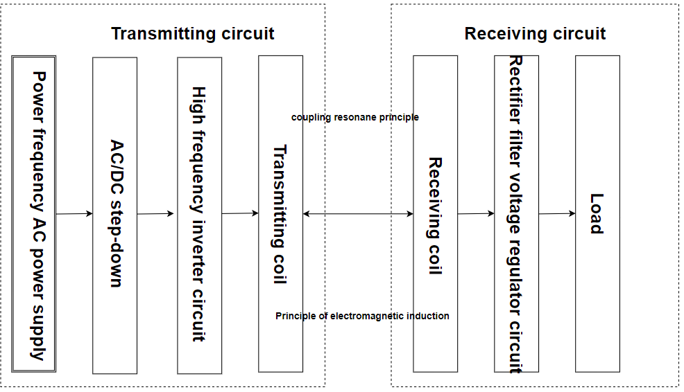
Figure 1. Block Diagram of Magnetic Coupled Resonant Wireless Energy Transmission System
The input DC is first converted into high-frequency AC, and then transmitted to the transmitting end to generate a high-frequency alternating magnetic field energy. At this time, the receiving coil generates induction electromotive force and induction current through the principle of electromagnetic induction, thereby realizing wireless energy transmission. The energy ultimately reaches the load after rectification and filtering.
2.2. Analysis of two-coil circuit structure and working principle
For WPT systems, series-string equivalent circuits are usually used for analysis as shown in Figure 2.
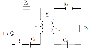
Figure 2. Two Coil Structure System - Series - Series Structure Equivalent Circuit Diagram
Based on Kirchhoff’s law, the following equation can be derived:
= (1)
where \( ω \) is the resonant angular frequency, the power supply at the transmitting end has an RMS value of \( {U_{in}} \) , and the internal resistance is Rs. The transmitting coil has an inductance L1 and an equivalent internal resistance R1. The coil at the receiving end has inductance L2 and equivalent internal resistance R2, and the mutual inductance between the two coils is M. The transmission distance is D. The compensation capacitances in each loop at resonance are C1 and C2, respectively. the load resistance is RL, and the currents in the two loops are I1 and I2, respectively. When the system is operating at resonance, then:
\( jw{L_{1}}+\frac{1}{jw{C_{1}}}=0 \) (2)
\( jw{L_{2}}+\frac{1}{jw{C_{2}}}=0 \) (3)
The two loop current values are:
\( {i_{1}}=\frac{({R_{L}}+{R_{2}}){U_{in}}}{({R_{s}}+{R_{1}})({R_{L}}+{R_{2}})+{(ωM)^{2}}} \) (4)
\( {i_{2}}=\frac{jωM{U_{in}}}{({R_{s}}+{R_{1}})({R_{L}}+{R_{2}})+{(ωM)^{2}}} \) (5)
The input power, output power, and transmission efficiency \( η \) are obtained by coupling the loop equations (1), (4), and (5):
\( {P_{in}}={U_{in}}{i_{1}}\frac{({R_{L}}+{R_{2}})U_{in}^{2}}{({R_{s}}+{R_{1}})({R_{L}}{+R_{2}}){(ωM)^{2}}} \) (6)
\( {P_{in}}={i_{2}^{2}R_{L}}=\frac{{(ωM)^{2}}U_{in}^{2}{R_{L}}}{{[({R_{s}}+{R_{1}})({R_{L}}{+R_{2}}){(ωM)^{2}}]^{2}}} \) (7)
\( η=\frac{{P_{L}}}{{P_{in}}}=\frac{{R_{L}}{(ωM)^{2}}}{({R_{L}}+{R_{2}})×[({R_{s}}+{R_{1}})({R_{L}}{+R_{2}}){(ωM)^{2}}]}×1 \) 00%(8)
From the above equation, it is obtained that when the coil structure and load are certain, the transmission efficiency of the system will be affected with several factors such as frequency \( ω \) , mutual inductance M of the coil and load. In turn, the mutual inductance coefficient M is related to the transmission distance between the receiving and transmitting coils, then:
\( M=\frac{πμ{N_{1}}{N_{2}}r_{1}^{2}r_{2}^{2}}{2{({D^{2}}+r_{1}^{2})^{\frac{3}{2}}}} \) (9)
where \( μ \) is the vacuum permeability; r is the coil radius; N is the number of coil turns; and D is the transmission distance. From the equation, it can be seen that the larger the transmission distance D, the smaller the mutual inductance coefficient M, and at the same time the lower the transmission efficiency, and vice versa.
3. Methodology
3.1. Design of Magnetic Coupling Resonant Wireless Energy Transmission Device
The device is a radio energy transmission system based on single chip microcomputer and the PWM core part of the single chip microcomputer is considered. With regard to the actual AC power supply, a DC power module is used for the purpose of supplying the requisite DC power to the transmission unit [5]. In order to meet the requirements of the system, the K7805-1000R3L power module is used to provide 5V to the MCU, and the 5V voltage is increased to 24V for the output circuit, and the level of PWM signal output is matched through the EG2104 chip. In order to generate a strong alternating magnetic field, a high frequency inverter circuit using MOSFET is designed to convert direct current into high frequency alternating current. This device uses a simple voltage inverter circuit structure which is suitable for little load change. Through the design of the transmitter circuit, high-frequency alternating magnetic field energy is obtained [6], and the receiving end generates induced electromotive force and current through the principle of electromagnetic induction, which is converted into DC electricity through the single-phase rectifier bridge circuit based on four Schottky diodes, and combines the 7805 integrated voltage regulator circuit and capacitor filter to ensure a stable output of 5V DC voltage to the load. This is shown in Figure 3.
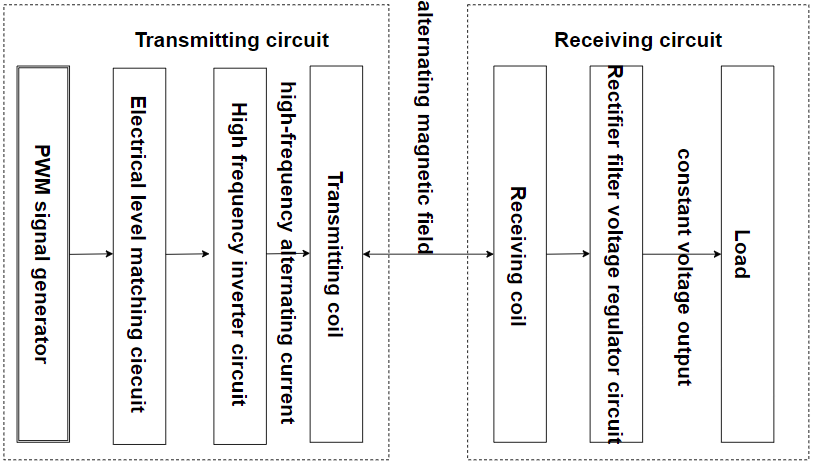
Figure 3. System Block Diagram of Magnetically Coupled Resonant Wireless Energy Transmission Device
3.2. Design of Each Part of Wireless Energy Transmission Device
3.2.1. MCU PWM Signal Generator. Based on the PWM module characteristics of STC15W4K32S4 single-chip microcomputer series, the duty cycle and frequency of any PWM output can be adjusted, and the complementary symmetrical output of any two PWM modules can be realized [7]. The circuit schematic diagram of the single chip microcomputer is shown in Figure 4, where P2.1 and P3.7 are output pins of PWM1 and PWM2 respectively, outputting two complementary symmetrical PWM rectangular waves. The P0.2 port provides a high level input to the SD pin of the EG2104 chip used in the next level matching circuit so that the EG2104 can function properly.
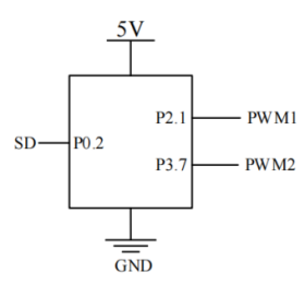
Figure 4. PWM Module Waveform Generator Block Diagram
3.2.2. Level Matching Circuit. The EG2104 chip is used as the level-shifting matching circuit as the PWM output voltage (3.3V or 5V) of the STC15W4K32S4 microcontroller does not align with the 24V voltage necessary for the transmitter circuit. Designed for driving MOS and IGBT tubes, the EG2104 integrates logic signal processing, dead-time control, level shift, and output driver functions without the need for additional dead-time Settings. A 200KΩ pull-down resistor is built into the SD pin and connected to the P0.2 port of the microcontroller to maintain a high level and activate the four MOS tubes. VB is connected to 24V power supply, and VCC is connected to 5V power supply. By controlling the HO and LO ports of EG2104, an effective transmitting circuit driver is realized.
3.2.3. High Frequency Inverter Circuit. The IRF540N MOSFET is selected as the core switching element due to its excellent electrical characteristics, including a drain-source breakdown voltage of up to 100V and a gate-source voltage range of ±20V, which ensures high voltage withstand capability. The threshold voltages between 4.5V and 4V facilitate stable switching control, and the IRF540N supports continuous drain currents up to 33A, thereby meeting system current capacity requirements. Moreover, the IRF540N’s rapid switching speed of 35ns and minimal on-resistance offer optimal performance in high-frequency inverting circuits, enhancing circuit efficiency. .
3.2.4. Receiving End Rectifier Voltage Regulator Circuit. It is not feasible for conventional diodes to process high-frequency signals, which may result in overheating or even damage to the circuitry. Accordingly, four MBR20200CS Schottky diodes were selected for the construction of the rectifier bridge at the receiver end. The AC power generated by the receiver coil is transmitted through the high-frequency rectifier bridge and subsequently filtered by a 100μF electrolytic capacitor, resulting in the generation of a relatively stable DC) power. Subsequently, the DC power is regulated by the 7805 regulator, which provides a stabilized voltage of 5V to the load.
3.3. Physical Device
This study uses a microcontroller pin to output a high-frequency PWM rectangular wave as the input source of the wireless energy transmission device, and the voltage level is boosted by a level matching circuit [8]. The transmitting coil then emits a high-frequency alternating current via a high-frequency inverting circuit, thereby generating a high-frequency alternating magnetic field. This differs from the conventional approach of utilizing a magnetically coupled resonant wireless energy transfer device, which employs an industrial frequency alternating current as the excitation source directly. The receiving coil acquires the energy transmitted by the transmitting end through the coupling resonance and subsequently outputs stable direct current to the load through the rectifier stabilized filter circuit. Figure 5 depicts the physical device.
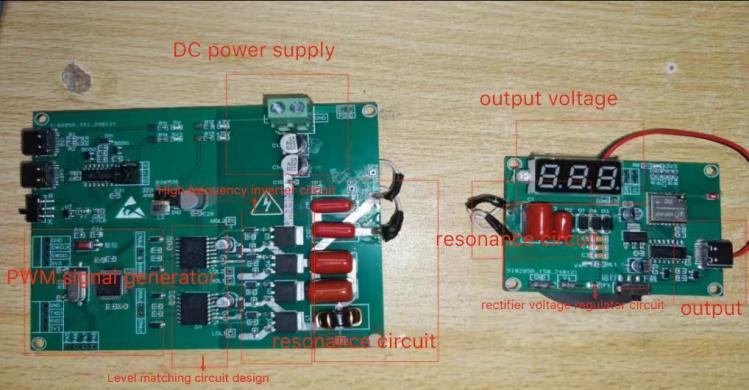
Figure 5. Physical Device Diagram of Magnetic Coupled Resonant Wireless Energy Transmission System
4. Results
4.1. Impact of Frequency on System Transmission Performance
The wireless energy transmission device designed in this study input 24V voltage 0.5A current through 12W power adapter to supply power to each module. The two-coil series-series structure model is selected in the experimental device. According to the inductance of the selected coupling coil 10 µH and the fixed resonant frequency of the system 100 kHz, the value of the selected capacitor C can be calculated to be 250µF. When the transmission distance of the radio energy transmission system is fixed at 9mm, the load impedance of the receiving end is set to 5Ω, the PWM frequency of the radio energy transmission system is changed to change the transmission frequency of the system, the output voltage of the receiving end of the system is recorded, and the calculated output power data is recorded in Table 1.
Table 1. Relation between Output Power and Transmission Frequency
Output Frequency (KHZ) | Output Power (W) |
50 | 0.1 |
60 | 0.2 |
70 | 1.5 |
80 | 2 |
90 | 3 |
100 | 4.5 |
110 | 4 |
120 | 3.8 |
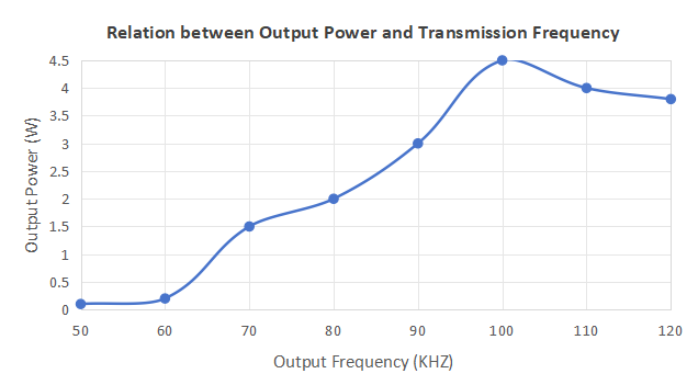
Figure 6. The Relationship between Output Power and Transmission Frequency
According to Figure 6, it can be found that the higher the frequency, the output power of the system first increases and then decreases. When it reaches the resonant frequency, the output power of the system will reach the maximum. The analysis shows that the transmission frequency of the radio energy transmission system is consistent with the inherent resonant frequency of the line, so that the maximum output power can be obtained.
4.2. Impact of Load Impedance on Transmission Performance
To investigate the load capacity of the wireless energy transmission system designed in this study, it is necessary to perform a physical power test on the transmission equipment to vary the load impedance. When the transmission distance of the wireless energy transmission system is fixed at 9 mm and the transmission frequency of the system is fixed at 100 KHz, the load impedance value at the receiving end of the wireless energy transmission system is changed, the input voltage and input current at the transmitting end are measured, and the output voltage and output current at the receiving end are calculated to obtain the transmission efficiency of the system. Table 2 presents the measured data.
Table 2. Relation between Output Power P and Load Impedance RL
Load Impedance (Ω) | Output Power (W) |
15 | 1.6 |
10 | 2.38 |
9 | 2.63 |
8 | 2.95 |
7 | 3.6 |
6 | 3.88 |
5 | 4.63 |
4 | 4.78 |
3 | 4.44 |
2 | 2.98 |
1 | 1.74 |
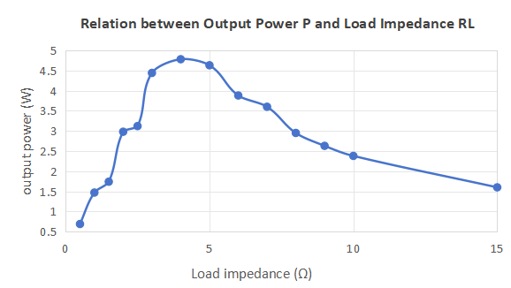
Figure 7. Relationship between Output Power and Negative Carrier Frequency Impedance
As the load impedance value of the system increases gradually, the output power presents a pattern of initial growth followed by a decline, indicating that the system is capable of attaining its maximum output power at a specific load impedance value, as shown in Table 2 and Figure 7. Specifically, when the load impedance is 4Ω, the maximum output power of the system is 4.78 W. As the load impedance increases, the transmission efficiency shows a rapid initial increase, followed by a gradual decrease.
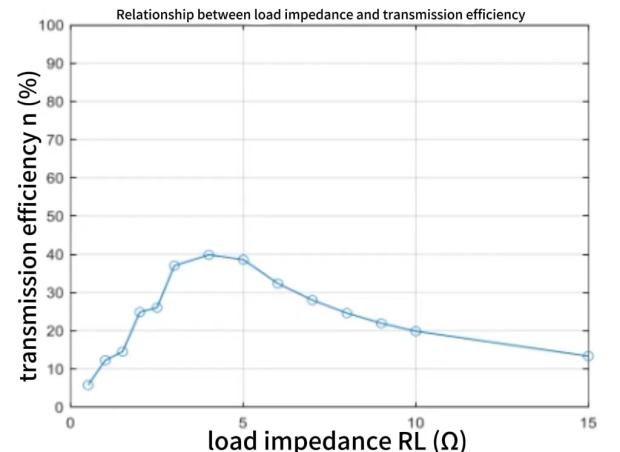
Figure 8. Relationship between Load Impedance and Transmission Efficiency
According to Figure 8, when the load impedance is 5Ω, the system transmission efficiency reaches the highest value of 39.67%.A comparison of Figure 7 and Figure 8 reveals that the system exhibits a correspondence between load impedance and the attainment of maximum output power and maximum transmission efficiency. This phenomenon is consistent with the law of maximum power transmission, which states that in order to achieve maximum output power transmission, the load impedance needs to match the conjugate complex impedance of the source, while in order to achieve maximum efficiency, different matching conditions may be required. Therefore, when the system pursues the maximum output power and the maximum transmission efficiency, it will correspond to different load impedance values.
4.3. The influence of transmission distance on transmission performance
In order to further investigate the power transmission performance of the radio energy transmission system designed in this research institute at different transmission distances, the load impedance of the system is kept constant at 5 Ω and the transmission frequency is set at 100 KHz. By adjusting the distance between the receiving and transmitting coils, the input voltage and current at the transmitting end and the output voltage and current at the receiving end are measured and recorded. Based on these data, the input power and output power of the system are calculated and the transmission efficiency will be derived from them. The measured data are recorded in Table 3.
Table 3. The Relationship between Output Power P and Transmission Distance L
Transmission Distance (mm) | Output Power (W) |
7 | 5.04 |
8 | 4.87 |
9 | 4.61 |
10 | 4.65 |
11 | 4.3 |
12 | 4.08 |
13 | 3.89 |
14 | 3.54 |
15 | 3.23 |
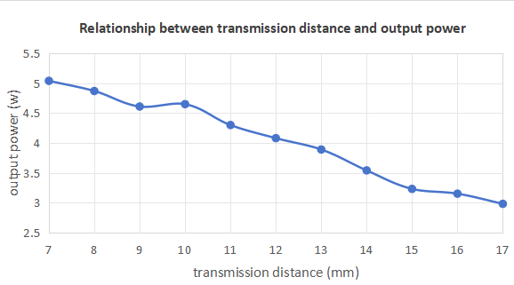
Figure 9. The Relationship between Transmission Distance and Output Power
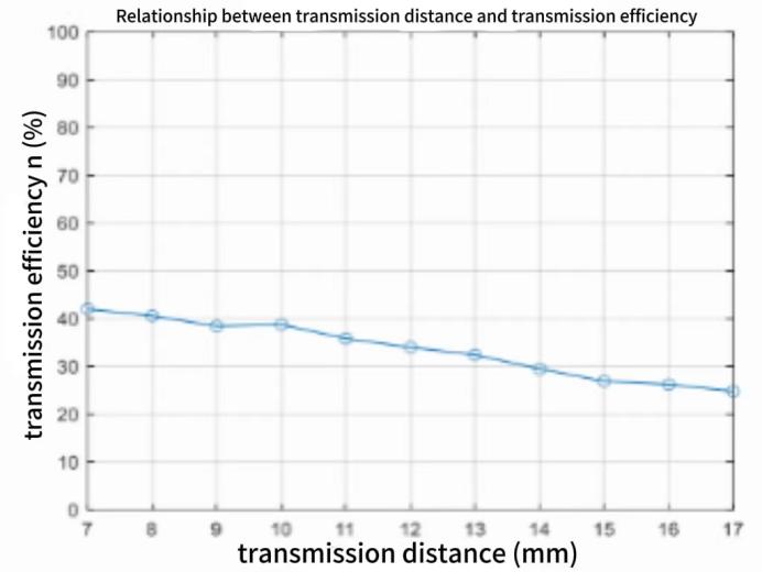
Figure 10. The relationship between transmission distance and transmission efficiency
According to Table 3, Figure 9 and Figure 10, an increase in transmission distance is associated with a gradual decline in system output power and a corresponding reduction in transmission efficiency. Accordingly, in order to achieve enhanced transmission power and efficiency, it is essential to minimize the distance between the transmitting and receiving coils during power transmission.
5. Discussion
5.1. Impedance Matching
In the two-coil series-series structure radio energy transmission system, the capacitor compensation self-inductance technology realizes the current ratio matching of primary and secondary side coils by adjusting the equivalent load resistance, and optimizes the system efficiency. The technology takes into account changes in coupling coefficient and load resistance fluctuations to effectively track and maintain maximum efficiency points, improving system efficiency and reliability.
5.2. Frequency Tracking
To address the problem of resonant frequency drift in wireless energy transmission systems, a method for automatically adjusting the transmission frequency is proposed. The method compares the actual transmission efficiency and the set efficiency in real time, and automatically adjusts the transmission frequency to keep the resonance frequency matching, so as to improve the transmission efficiency and system stability. This strategy can adapt to changes in circuit parameters and external environment to ensure the long-term stable operation of the system.
6. Conclusion
In this paper, the correlation between the resonant frequency and the component parameters is discussed by analyzing the calculation formula, and there is a mutual constraint relationship between the parameters, so in order to achieve the maximum transmission performance, each parameter must be matched. A coupled resonant radio energy transmission device is designed and the generator, level matching circuit, high frequency inverter circuit module, two coupling coils, series resonant capacitor and rectifier regulator filter circuit are investigated. The transmission frequency, load impedance and transmission distance, which are independent variables, were tested through experiments on the power transmission device. It has been found that wireless energy transmission should keep the frequency in line with the resonant frequency in order to output maximum power. Different load impedances affect the transmission efficiency. Shortening the transmission distance can increase the transmission efficiency. Through these studies, the design of the wireless energy transmission device is carried out under over-idealized circuit parameters, but the results of the physical device power test are not ideal, thus realizing the disconnection between theory and practice. In addition, there are many issues to be further explored, such as how to optimize the coil design, improve the transmission performance, and make the transmission reach the maximum power transfer efficiency, etc. There is room for research and exploration. The system structure and algorithms will be further optimized in the future to achieve more efficient energy transmission and a wider range of application scenarios.
References
[1]. Kurs, A., Karalis, A., Moffatt, R., et al. (2007) Wireless Power Transfer via Strongly Coupled Magnetic Resonances. Science, 317(5834) : 83-86.
[2]. Lee, C.H., Jung, G., et al. (2020) Wireless Power Transfer System for an Autonomous Electric Vehicle. IEEE Wireless Power Transfer Conference (WPTC), Seoul, Korea(South), 467-470.
[3]. Li, Y., et al. (2023) Electrical Experiment Teaching of Magnetic Coupled Resonant Wireless Transmission Technology. Laboratory Research and Exploration, 42(11): 206-210.
[4]. Xue, C. (2024) Research on magnetic coupled resonant radio Energy Transmission System. Lanzhou University of Technology, Lanzhou.
[5]. Yang, H., Wu, J. and Hu,W. (2015) Implementation of simple Wireless Energy Transmission System based on single Chip Microcomputer. Automation & Instrumentation, 07: 5-8.
[6]. Hao, Z., Duan, Y., Han, B., et al. (2019) Design of magnetic Coupling Resonant Radio Energy Transmission System based on Single Chip Microcomputer. Electronic Testing, 2: 33-36.
[7]. Ding, X. and Chen, C. (2015) Principles and Interfaces of Monolithic Microcomputers: Based on STC15W4K32S4 Series Microcontrollers. Publishing House of Electronics Industry, Beijing.
[8]. Chen, C. and Deng, J. (2012) Design of Radio Energy Transmission Device based on Enhanced PWM. Information Technology, 7: 41-45.
Cite this article
Zhong,Z. (2024). Design and implementation of wireless power transfer device. Applied and Computational Engineering,81,119-128.
Data availability
The datasets used and/or analyzed during the current study will be available from the authors upon reasonable request.
Disclaimer/Publisher's Note
The statements, opinions and data contained in all publications are solely those of the individual author(s) and contributor(s) and not of EWA Publishing and/or the editor(s). EWA Publishing and/or the editor(s) disclaim responsibility for any injury to people or property resulting from any ideas, methods, instructions or products referred to in the content.
About volume
Volume title: Proceedings of the 2nd International Conference on Machine Learning and Automation
© 2024 by the author(s). Licensee EWA Publishing, Oxford, UK. This article is an open access article distributed under the terms and
conditions of the Creative Commons Attribution (CC BY) license. Authors who
publish this series agree to the following terms:
1. Authors retain copyright and grant the series right of first publication with the work simultaneously licensed under a Creative Commons
Attribution License that allows others to share the work with an acknowledgment of the work's authorship and initial publication in this
series.
2. Authors are able to enter into separate, additional contractual arrangements for the non-exclusive distribution of the series's published
version of the work (e.g., post it to an institutional repository or publish it in a book), with an acknowledgment of its initial
publication in this series.
3. Authors are permitted and encouraged to post their work online (e.g., in institutional repositories or on their website) prior to and
during the submission process, as it can lead to productive exchanges, as well as earlier and greater citation of published work (See
Open access policy for details).
References
[1]. Kurs, A., Karalis, A., Moffatt, R., et al. (2007) Wireless Power Transfer via Strongly Coupled Magnetic Resonances. Science, 317(5834) : 83-86.
[2]. Lee, C.H., Jung, G., et al. (2020) Wireless Power Transfer System for an Autonomous Electric Vehicle. IEEE Wireless Power Transfer Conference (WPTC), Seoul, Korea(South), 467-470.
[3]. Li, Y., et al. (2023) Electrical Experiment Teaching of Magnetic Coupled Resonant Wireless Transmission Technology. Laboratory Research and Exploration, 42(11): 206-210.
[4]. Xue, C. (2024) Research on magnetic coupled resonant radio Energy Transmission System. Lanzhou University of Technology, Lanzhou.
[5]. Yang, H., Wu, J. and Hu,W. (2015) Implementation of simple Wireless Energy Transmission System based on single Chip Microcomputer. Automation & Instrumentation, 07: 5-8.
[6]. Hao, Z., Duan, Y., Han, B., et al. (2019) Design of magnetic Coupling Resonant Radio Energy Transmission System based on Single Chip Microcomputer. Electronic Testing, 2: 33-36.
[7]. Ding, X. and Chen, C. (2015) Principles and Interfaces of Monolithic Microcomputers: Based on STC15W4K32S4 Series Microcontrollers. Publishing House of Electronics Industry, Beijing.
[8]. Chen, C. and Deng, J. (2012) Design of Radio Energy Transmission Device based on Enhanced PWM. Information Technology, 7: 41-45.