


1. Introduction
Glass curtain wall of high-rise building does have a lot of advantages like it makes the building looks shining and integrated. However, dusts and water logging can make the glass curtain wall faded, and these are not wanted. To ensure a clean appearance of the building, people have to clean glass curtain wall regularly. In the past few decades, people have come up with a lot of ways to clean glass curtain. For instance, people may use secure belts or bracket to lift cleaner to air around the building, and they can clean the glass curtain wall manually by brushes. Although this traditional approach is easy to conduct and less costly, it may may cause severe injury to cleaner if suffer from wind and storms. This is because the bracket which used to carry cleaner is lifted by ropes from the roof and stabilized by its own gravity. The bracket will swing when suffered from forces like big wind or collisions. To replace old time consuming and dangerous manual cleaning, a brand-new way, glass curtain wall cleaning robots, seems to take this role. Robots can work continuously to achieve higher efficiency, and they will not be affected by bad weather especially huge wind and storm. To improve cleaning efficiency and ensure safety of cleaners, it is an urgent to develop a climbing robot that can independently complete the cleaning task of high-rise building glass curtain walls [1]. In past few years, a lot of cleaning robots showed up in the market, but there is still a certain gap between the performance of glass curtain wall cleaning robot and the goal of Zhao [2]. Now, the turning circle radius of most robots is too small and sharp, which attracts longer turning distance and in turn affects its working efficiency [3]. Their path planning at turning can still be optimized to achieve higher efficiency. In following parts of this paper, several experiments will be done to discover how time needed to turn by robots will be affected by rotational direction and speed of motors. Besides, considering a specific maze with a 90-degree sharp left turning, a series of simulations based on Robotics Playground will be conducted to make the whole optimizing process visible and comparable. Conclusively, by optimizing operating logics, this paper aims to improve the overall efficiency of cleaning robot by saving time at turnings.
2. Literature Review
There are some papers discussing path planning ability of cleaning robot. Ash Yaw Sang Wan explains that complete area coverage is very crucial part of path planning work of robots [4]. They have introduced a new cleaning approach called linear wiping by using inhouse dual-arm robot system. Complete area coverage is very important for the reason that any uncleaned area will be more visible and outstanding compared with cleaned area. At the same time, cleaning in sequence makes the whole cleaning process systematic. This optimizes efficiency as it maximumly reduces the possibility of repeat cleaning. Even this approach increases the overall efficiency, it did not focus on refining the turning path. Besides, some of the researchers investigated using grey wolf optimizer (GWO) algorithm to optimize obstacle avoiding and path planning ability of ground cleaning robot [5]. Faten Hamad utilized the technique of parallel comparison to find the difference among GWO and other optimizing techniques like discrete artificial bee colony, artificial bee colony and particle swarm optimization. Under the result of their six experiments, GWO is the one which convergent the fastest one. GWO is a very nice technique to optimize the obstacle avoidance ability, however, it not focused on optimizing the turning curve of robots [6]. There is a lot of research have been done, however, most of them are trying to optimize the fundamental operating logic of robot [7]. Other than doing research on what should robot do or how they should act when facing obstacles, this research focus on how robots can pass the turning in the fastest way while keeping turning circle smooth and fluent.
3. Methodology
3.1. Research Design
Firstly, a basic robot operating logic has been established in robotic playground, as shown in Figure 1. Three distance detecting sensor were installed in the front, front left and front right of the robot to detect distance from itself to the obstacle. They are all connected to the controller and the signal received will be transport to left and right motors. Equipped with these hardware, the cleaning robot can do simple path planning and avoid obstacles by itself. Basically, the idea of this paper is to optimize the operating efficiency of the robot by maximizing distance it travels in fixed period of time. To do so, a maze with a 90-degree sharp left turning like graph 2 has been built in robotics playground for the robot to pass. The robot needs to start from bottom left corner, do a 90-degree left turning, finally straight to top right corner. Time needed from start (bottom left corner) to the end (top right corner) will be recorded and compared among different simulations. Rotational speed and direction of both motors and detecting distance will be adjusted based on the performance of the robot in previous experiment.
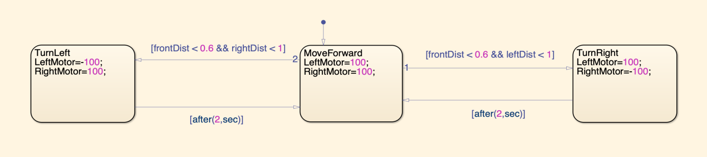
Figure 1. Logic Process Flow Chart of Cleaning Robot
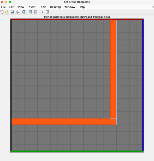
Figure 2. Shape of the Maze
3.2. Simulation Environment
In this research, simulations are based on MATLAB 2024b and its robotics playground add-on. In a 20 by 20 maze, facilitated with maze editing function, a path with a 90-degree left turnings has been designed for the robot to pass. Orange walls are obstacles which cannot be passed but can be detected as walls by sensors on robot. In both zone A and zone B, the path is 4 units width, and 4*4 at the corner. Additionally, bottom left corner is considered as start and top right corner is the destination. The robot has to start from bottom left and go 18 units right. After that, do a left turning and go 18 units upward direct to the destination.
3.3. Data Collection and Processing
In first experiment, there are three simulations. Front detecting distance has been set to increase from 0.6 to 1 by 0.2, and right detecting distance was 1. When turning, rotational speed of left motor is -100 and the right one is 100. Robots used about 45.7s travel from start to the end. In these simulations, robots firstly stopped and turned in place as two motors rotates at same speed but opposite direction. Robots successfully got to the destination in the end, but it acts too late at turnings and failed to utilize most of room possible. At the same time, turning is too sharp and stiff which attracts longer travel distance and wastes several seconds. This might be avoided by increasing turning radius to make the turning smoother. Specific experimental results and data are shown in Table 1.
Table 1. Experiment Results and Data
Number of Experiment # | Number of Simulation # | Front Detecting Distance | Left/Right Distance | Left/Right Motor Speed | Reach End? Time? | Average Speed | Turning Radius |
1st | 1st | F0.6 | L1 / R1 | L-100 / R100 | 45.91s | 0.87 | \ |
2nd | F0.8 | L1 / R1 | L-100 / R100 | 45.57s | 0.878 | ||
3rd | F1 | L1 / R1 | L-100 / R100 | 45.64s | 0.876 | ||
2nd | 1st | F0.6 | L1 / R1 | L20 / R100 | Stucked at Zone B | \ | 0.2 |
2nd | F0.8 | L1 / R1 | L20 / R100 | Stucked at Zone B | \ | ||
3rd | F1 | L1 / R1 | L20 / R100 | 44.5s | 0.899 | ||
3rd | 1st | F1 | L1 / R1 | L30 / R110 | Stucked at Zone B | \ | 0.273 |
2nd | F1.2 | L1 / R1 | L30 / R110 | 43.46s | 0.921 | ||
3rd | F1.4 | L1 / R1 | L30 / R110 | 43.38s | 0.922 | ||
4th | F1.6 | L1 / R1 | L30 / R110 | Stucked at Corner | \ | ||
5th | F1.8 | L1 / R1 | L30 / R110 | Stucked at Corner | \ | ||
4th | 1st | F1 | L1 / R1 | L40 / R120 | 43.2s | 0.926 | 0.333 |
2nd | F1.2 | L1 / R1 | L40 / R120 | 43.88s | 0.912 | ||
3rd | F1.4 | L1 / R1 | L40 / R120 | 43.12s | 0.928 | ||
4th | F1.6 | L1 / R1 | L40 / R120 | 42.88s | 0.933 | ||
5th | F1.8 | L1 / R1 | L40 / R120 | Stucked at Corner | \ | ||
5th | 1st | F1 | L1 / R1 | L50 / R140 | 40.97s | 0.976 | 0.357 |
2nd | F1.2 | L1 / R1 | L50 / R140 | 40.2s | 0.995 | ||
3rd | F1.4 | L1 / R1 | L50 / R140 | 40.92s | 0.978 | ||
4th | F1.6 | L1 / R1 | L50 / R140 | 40.33s | 0.992 | ||
5th | F1.8 | L1 / R1 | L50 / R140 | Stucked at Corner | \ | ||
6th | 1st | F1 | L1 / R1 | L70 / R180 | Stucked at Zone B | \ | 0.389 |
2nd | F1.2 | L1 / R1 | L70 / R180 | 40.68s | 0.982 | ||
3rd | F1.4 | L1 / R1 | L70 / R180 | 39.81s | 1.005 | ||
4th | F1.6 | L1 / R1 | L70 / R180 | Stucked at Corner | \ | ||
5th | F1.8 | L1 / R1 | L70 / R180 | Stucked at Corner | \ | ||
7th | 1st | F1 | L1 / R1 | L80 / R200 | Stucked at Zone B | \ | \ |
2nd | F1.2 | L1 / R1 | L80 / R200 | Stucked at Zone B | \ | ||
3rd | F1.4 | L1 / R1 | L80 / R200 | Stucked at Zone B | \ | ||
4th | F1.6 | L1 / R1 | L80 / R200 | Stucked at Corner | \ | ||
5th | F1.8 | L1 / R1 | L80 / R200 | Stucked at Corner | \ |
To verify assumption in first experiment that efficiency and smoothness can be optimized by increasing turning radius, rotational speed of left motor was increased to 20 in the same direction with right motor while keeping speed of right motor unchanged. From data of three simulations in second experiment. This method indeed increased turning radius by:
Calculation of Turning Radius:
\( Speed=Angular Speed*Radius \) (1)
Set the width of the robot to 2 up to the width:
\( v(left Motor)=ω*r \) (2)
\( v(Right Motor)=ω*(r+2) \) (3)
Combine two equations:
\( \frac{ω*r}{ω*(r+2)}= \frac{V(left)}{V(right)} \) (4)
Set \( \frac{V(left)}{V(right)}=n \) :
\( \frac{r}{r+2}= n \) (5)
\( r= n*r+2n (2.3) \) (6)
\( r=\frac{2*n}{1-n} (2.4) \) (7)
This time, turning became smooth and fluent. From aspect of travel distance, the path was shortened 21% and saved 0.5 seconds. In first and second simulation, as the turning radius was too large, robot was unable to finish turning if it starts to turn when its 0.6-unit length or 0.8-unit length away from the obstacle. As a result, the robot was stuck at the wall of zone B. In third simulation, front detecting distance was 1 which is two times greater than the turning radius. The robot turned successfully but very close to the wall of zone B after turning. So, the logic can still be optimized to better utilize room around the corner. This might be achieved by further increase front detecting distance and increasing turning radius.
In following experiments, both motors continue to increase rotating speed to further enlarge turning radius. In experiment 3, speed of left and right motor has been adjusted to 30 and 110. This attracts a turning radius of 0.273. Under this combination of motor speed, the robot is very likely to be stuck. In first simulation, 1 unit length front detecting distance is too small for the robot, so it stuck at wall of zone B. For simulation 4 and 5, left wheel will scratch the corner and brought drag force to the robot and slow it down. The robot can only pass the corner when front detecting distance is 1.2 and 1.4. In fourth experiment, passing rate is much higher than previous experiments. In first four simulations in this experiment, room is enough for the robot to finish left turning but did not save too much time. In the last simulation, the robot was stuck at the corner as the turning happens too early. Average time needed to pass is 43.27s and shortest time to pass is 42.88s, which still did not have any big improvements. In following experiments, to further increase turning radius, speed of motors has been increased to 50/140, 70/180 and 80/200, which in turn brings larger turning radius of 0.333, 0.357 and 0.389. For experiment 4 and 5, increment of speed of motors and turning radius did not make too big difference in the performance. Only a few seconds have been saved as expected. And for the fifth simulation of these two experiments, the turning radius is still too small and will stuck on the wall of zone B for the same reason in the third experiment.
Lastly, the robot reaches the limit of this maze in experiment 6 and 7. Speed of motors has been increased to 70/180. This correspondingly increased turning radius to 0.389, which is very high for the robot. As we can see from the experiment result, the robot will stuck either at the wall of zone B or the corner if the front detecting distance is too small or large. This means that the ‘gap’ of pass is getting smaller as the turning radius increases. In experiment 7, robot cannot pass the corner no matter what detecting distance is. This means that the robot reaches the limit of the maze and utilizes most of the room possible. Finally, the robot keeps a similar speed as that of going straight.
4. Results
From an analytical standpoint, modifying detecting distance only does no effect on optimizing turning efficiency of the robot as it only makes the turning process happens a little bit earlier. Distance is same across six simulations in first two experiments. According to calculations of turning radius:
Unoptimized Path (Right Angle) = \( 2×R \) (8)
Optimized Path (Curve) = \( \frac{1}{2} × π × R \) (9)
Distance Saved = \( 2×R-\frac{1}{2}×π×R \) (10)
\( Percentage Saved = \frac{(2 × R- \frac{π}{2} × R) }{2 × R} ≈21.46\% \) (11)
Regarding equation 3.1, compared with optimized turning logic robot with turning radius R, the distance needed by old logic is two times R as it turns in place. Assuming turning radius of optimized turning logic is R, so the distance of the curve needed by robot to turn is as the equation 3.2. Total distances saved is the difference between equation 3.2 and 3.1, as shown in equation 3.3. Compared with first experiment, which did not have turning radius, following experiments saved time at turnings because the distance is shorter. Then, experiment 3 and 4 shows that not too much time been saved by increasing turning radius relatively small amount. Only one second faster is not too meaning for our optimization. Afterwards, to see more effect on time saving, turning radius increase at a faster rate in following experiments. travel distance has been reduced by: Conclusively, in first experiment, three simulations have verified that increasing front detecting distance can only make the turning process happen a little bit earlier but has no effect on increasing smoothness and efficiency of turning process. Then, following experiments have verified that more time will be saved if increasing turning radius at a faster rate
5. Conclusion
At the end of this research, overall efficiency of the glass curtain wall cleaning robot has been improved by refining turning path and reducing turning distance. By optimizing control logic and path planning, a combination of rotational speed of both motors has been found so that the robot can pass the specific 90-degree left turning in shortest time. A much smooth turning makes the clean area more even, and the whole process much elegant. In robots’ daily service, old robots need to stop 4 times to pass an obstacle. However, optimized parameters enable them pass obstacles without stop. So, they can work and move continuously to get a much better efficiency, which means creating more value. Compared with old robots, 21.46 percent of turning distance and about 5 seconds was saved under the specific maze in this research. However, there is some drawbacks of this research. Although a lot of simulations have been done based on the specific maze, experiment data is still limited to converge to a more accurate set of parameters. The gap of parameters of motors between two sets of experiment is 10 in this research. Ideally, the gap should be infinitely small, and the outcome will be a curve. The graph enables readers to read the trend of convergence of results much easier. Due to limited computing recourses, smallest resolution of this research is limited to 10 but still keeps a reasonable accuracy to show readers basic idea of refining turning curve.
References
[1]. Hou, X., et al. (2024) The Structural Design of a Robot for Cleaning High-Rise Glass Curtain Walls. Mechanical & Electrical Engineering Technology, 53(04): 218-221.
[2]. Zhao, J. (2022) Research and Discussion on Machine Cleaning Method on Glass Wall Curtain. Academic Journal of Science and Technology.
[3]. Zhou, T. (2022) Research on Motion Path Control of Cleaning Robots. Zhejiang University, doi:10.27461/d.cnki.gzjdx.2020.004479.
[4]. Wan, A.Y.S., et al. (2024) Complete Area-Coverage Path Planner for Surface Cleaning in Hospital Settings using Mobile Dual-Arm Robot and GBNN with Heuristics. Complex Intell. Syst.
[5]. Hamad, F., Fakhouri, H.N., Alzghoul, F. and Zraqou, J. (2024) Development and Design of Object Avoider Robot and Object, Path Follower Robot Based on Artificial Intelligence. Arabian Journal for Science and Engineering.
[6]. Mirjalili, S., et al. (2014) Grey Wolf Optimizer. Advances in Engineering Software, 69: 46-61.
[7]. Yang, M., Xie, M. and Zhang, X. (2021) Obstacle Avoidance System and Path Planning Design for Cleaning Robots. Changjiang Information & Communications, 34(07): 14-17.
Cite this article
Feng,Q. (2024). Optimizing turning logic of glass curtain wall cleaning robot. Applied and Computational Engineering,81,158-163.
Data availability
The datasets used and/or analyzed during the current study will be available from the authors upon reasonable request.
Disclaimer/Publisher's Note
The statements, opinions and data contained in all publications are solely those of the individual author(s) and contributor(s) and not of EWA Publishing and/or the editor(s). EWA Publishing and/or the editor(s) disclaim responsibility for any injury to people or property resulting from any ideas, methods, instructions or products referred to in the content.
About volume
Volume title: Proceedings of the 2nd International Conference on Machine Learning and Automation
© 2024 by the author(s). Licensee EWA Publishing, Oxford, UK. This article is an open access article distributed under the terms and
conditions of the Creative Commons Attribution (CC BY) license. Authors who
publish this series agree to the following terms:
1. Authors retain copyright and grant the series right of first publication with the work simultaneously licensed under a Creative Commons
Attribution License that allows others to share the work with an acknowledgment of the work's authorship and initial publication in this
series.
2. Authors are able to enter into separate, additional contractual arrangements for the non-exclusive distribution of the series's published
version of the work (e.g., post it to an institutional repository or publish it in a book), with an acknowledgment of its initial
publication in this series.
3. Authors are permitted and encouraged to post their work online (e.g., in institutional repositories or on their website) prior to and
during the submission process, as it can lead to productive exchanges, as well as earlier and greater citation of published work (See
Open access policy for details).
References
[1]. Hou, X., et al. (2024) The Structural Design of a Robot for Cleaning High-Rise Glass Curtain Walls. Mechanical & Electrical Engineering Technology, 53(04): 218-221.
[2]. Zhao, J. (2022) Research and Discussion on Machine Cleaning Method on Glass Wall Curtain. Academic Journal of Science and Technology.
[3]. Zhou, T. (2022) Research on Motion Path Control of Cleaning Robots. Zhejiang University, doi:10.27461/d.cnki.gzjdx.2020.004479.
[4]. Wan, A.Y.S., et al. (2024) Complete Area-Coverage Path Planner for Surface Cleaning in Hospital Settings using Mobile Dual-Arm Robot and GBNN with Heuristics. Complex Intell. Syst.
[5]. Hamad, F., Fakhouri, H.N., Alzghoul, F. and Zraqou, J. (2024) Development and Design of Object Avoider Robot and Object, Path Follower Robot Based on Artificial Intelligence. Arabian Journal for Science and Engineering.
[6]. Mirjalili, S., et al. (2014) Grey Wolf Optimizer. Advances in Engineering Software, 69: 46-61.
[7]. Yang, M., Xie, M. and Zhang, X. (2021) Obstacle Avoidance System and Path Planning Design for Cleaning Robots. Changjiang Information & Communications, 34(07): 14-17.