1. Introduction
Nowadays, analogue circuits still play an important role in the development of science and technology, and the needs and applications of analogue circuits continue to expand and evolve in spite of the advances in digital technology and processing power. In recent years, for different application environments and needs, there have been many companies or technical teams that have developed amplifiers in different directions. For example, Analog Devices' AD8421 is a high-precision instrumentation amplifier that provides a high common-mode rejection ratio (CMRR) and low input bias current to accurately measure small signals while maintaining a high input impedance and low noise level, and is commonly used in medical instruments, industrial sensors, and data-acquisition systems to ensure the accuracy and stability of the measurements [1]. In addition to this, Analog Devices' ADL5602 is a high-performance RF amplifier that offers high gain, wide bandwidth, and excellent linearity with low noise characteristics. This amplifier can operate stably in applications with frequencies ranging from a few hundred MHz to several gigahertz, supporting the processing and amplification of high-frequency signals, which are widely used in wireless communication and radar systems [2]. Also, Texas Instruments' INA219 is a low-power operational amplifier for high-precision current monitoring, which is able to reduce energy consumption while maintaining high performance through optimised circuit design and the use of low-power technologies, making it suitable for use in portable devices and low-power systems [3]. Therefore, amplifiers, as one of the most important modules in analogue circuits, are very valuable for research, both in terms of theoretical knowledge and practical applications. The purpose of this paper is to present the reasons for increasing the amplifier gain and some technical or structural means of increasing the amplifier gain. Simulation experiments are also carried out on some amplifier structures to compare their advantages and disadvantages in several dimensions based on their various parameters.
2. Reasons for Increasing Amplifier Gain
Firstly, in electronic circuits, the input signal is usually weak and requires an amplifier to amplify it to a sufficient level so that subsequent circuits can handle it. Secondly, a higher gain can improve the signal-to-noise ratio of a system to some extent by boosting the ratio of the signal relative to the noise. What's more, certain applications require the amplifier to provide enough current or voltage to drive the load, and an increase in gain can help achieve this. Overall, increasing amplifier gain can improve the overall performance and accuracy of the system, but there is a need to balance gain with other design parameters such as bandwidth and stability [4].
3. Circuit Structure for Increasing Amplifier Gain
3.1. Basic common-source amplifier:
A common-source amplifier is a basic field-effect transistor amplifier circuit capable of high voltage gain. It amplifies the input signal by controlling the drain current by adjusting the gate voltage. It is presented and simulated in this paper only for comparative analysis with the subsequent circuit structure.
3.2. Common-source common-gate (cascode)
One way to improve the base gain unit (common-source amplifier) is to increase the resistance value of its output impedance Ro, which can be done by the common-gate amplifier as a current buffer, and thus the common-source common-gate amplifier was born. A common-source, common-gate structure refers to a common-source amplifier as the primary gain unit and a common-gate amplifier as a current buffer.
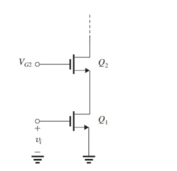
3.2.1. Sleeve type common source and common gate. As shown in Fig.1, in the case of an ideal current source, and assuming that the two MOS tubes Q1, Q2 are perfectly matched, according to the theoretical derivation of the amplifier gain Avo = -Ao2 , that is, the previous inherent gain to the original gain of the square times.
|
|
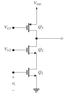
Figure 1. Ideal current source for load. | Figure 2. PMOS current mirror for load. |
Next, consider the case of an imperfect current source, assuming that the current source is a PMOS current mirror, as shown in Fig.2, at which point the voltage gain falls back to Ao. Here the current snubber Q2 fails. That is to say, it is useless just to raise the output impedance of Q1, but must also raise the output impedance of Q3. Therefore, Q3 can also be connected in series with a current buffer, as shown in Fig.3, assuming that the four MOS tubes are perfectly matched, the voltage gain is: Av = -1/2 Ao2. At this point, the voltage gain with the ideal conditions of the same order, the gain effect is better.
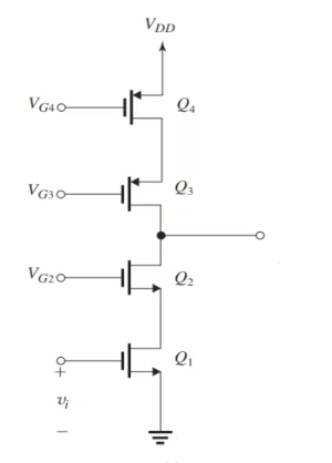
Figure 3. Common source common gate current mirror as a load.
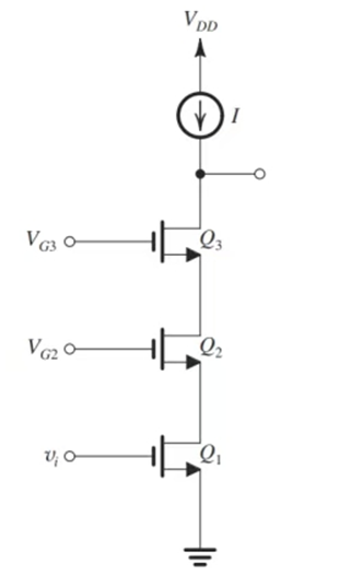
Figure 4. Common source dualstage common gate amplifier.
If a higher voltage gain is also required, then a higher output impedance is needed, and it naturally occurs to us that a common gate structure can be added to form a two-stage current snubber, as shown in Fig.4. Similarly, the voltage gain under ideal conditions can be calculated as Av = Ao3. A disadvantage of this construction is that it causes the transistors to be stacked on the same drain branch. It is not enough to increase the output impedance of the common-source amplifier; the output impedance of the current mirror must also be increased. Therefore, the output of the current mirror also needs to incorporate another stage of the common-gate structure. At this point, there are six MOS transistors throughout the drain branch. Since each transistor needs to operate in the current mirror, it is necessary to add a common gate structure. Because each transistor needs to work in the saturation region, the VDS of each transistor cannot be less than VOV, so the total voltage drop in the 6VDS, then it is necessary to increase the value of VDD. However, in practice, for ICs, VDD is generally around 1V to 2V, which limits the maximum number of MOS transistors in the drain branch.
Overall, the sleeve type common source and common gate structure allows for very high gain by cascading multiple transistors. Due to this cascaded structure, the output impedance is very high, which facilitates higher gain and bandwidth. Moreover, compared to the folded architecture, the sleeve architecture can achieve lower power consumption at the same gain. However, due to the cascade structure, the output swing is relatively small and limited by the supply voltage. This can be improved by using a low threshold MOSFET to reduce the gate source voltage or a high impedance load to reduce the load effect to increase the output swing. In addition, it has a limited input common-mode voltage range and special attention needs to be paid to the voltage range of the input stage during design. Due to its structural characteristics, the sleeve architecture can be limited in performance at low supply voltages.
3.2.2. Folded Cascode Amplifier.
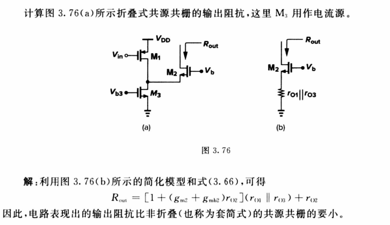
Figure 5. Folded common source and common gate structure[5].
As shown in Fig5, the folded common-source, common-gate amplifier is a common-source amplifier and a common-gate amplifier connected by a folded structure to increase the gain and bandwidth. It is analysed on a similar principle to the sleeve structure described above. Unlike the sleeve structure, the folded architecture allows a larger output voltage swing, which is especially important for low supply voltage applications. In addition, due to its design features, it is able to better balance gain and bandwidth. However, it has a relatively complex circuit structure that is more difficult to design and implement. Power consumption is relatively high due to the use of multiple current sources. In addition, the noise performance may be affected by the folded structure and requires careful design and optimisation. Based on the past literature, it can be seen that many architectural innovations have been proposed to improve the small- and large-signal operation of conventional folded cascade amplifiers [6].
To summarise, both seek to increase the output resistance of the amplifier to obtain higher gain [7]. Sleeved common-source common-gate, on the other hand, excels in terms of gain, but may require trade-offs in bandwidth and stability for applications requiring high gain, high output impedance, and low power consumption, such as high-gain amplifiers and RF applications. However, their output swing and input common-mode voltage range are limited, making them unsuitable for low-voltage environments. Folded common-source common-gate, on the other hand, provides a better balance between gain, bandwidth, and output swing for applications requiring large output swing and wide input common-mode voltage range, such as low-voltage operating environments. Despite the higher power consumption and design complexity, the overall performance is better, especially for low voltage and wide bandwidth applications.
Although the common source common gate structure has been proposed for a long time, its exploration has not stopped. For example, a high gain, low-noise common source common gate amplifier specifically designed for radio frequency (RF) applications[8]. In addition , there is an ultra wideband (UWB) low-noise amplifier designed specifically for 3.1-10.6 GHz. It applies a combination method of common gate cascade and self biased common source amplifier[9].There is also a broadband common gate CMOS low noise amplifier (LNA) suitable for multi-mode and multi band wireless communication applications[10].As process technology continues to improve, researchers have even created new co-gate structures and dual-gate (DG) MOSFETs to achieve smaller areas and lower parasitic RCs. On top of that, it has a power gain of up to 140GHz and an ultra-wide bandwidth compared to traditional co-grids[11].
3.3. Current cancellation techniques
Current cancellation technology is commonly used in amplifier design. By using additional circuits such as current mirrors to generate currents of equal magnitude but opposite direction to the unwanted current components, the offset effect can be achieved. This not only increases the gain of the amplifier, but also reduces distortion and noise in the circuit, improving overall performance. In this technology. Current mirror and OTA are two fundamental and crucial structures.
3.3.1. Basic current mirror.
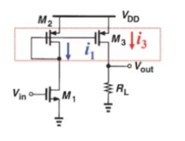
Figure 6. Schematic diagram of the basic current mirror.
As shown in Fig.6, the basic current mirror is a simple current replication circuit, usually consisting of two transistors. It is simple to design and implement, easy to understand and use, and has low cost and power consumption. However, over large signal ranges, the basic current mirror has poor linearity, which can lead to nonlinear distortion. The current gain is limited and not suitable for applications requiring high gain. Although the output impedance is high, it is not as high as that of current mirrors with complex structures, and the rejection of power supply noise is weak.
3.3.2. Active current mirror (Five-Transistor Operational Amplifier).A Five-Tube Operational Transconductance Amplifier (Five-Transistor OTA) is a common analogue circuit used in various signal processing applications. It is a voltage-controlled current source capable of converting an input voltage into an output current. As shown in Fig.7, it usually consists of three parts, namely, a differential input pair (M0, M1), which are two transistors that receive the differential input voltages ( Vin+) and ( Vin-); a current-mirror load (M2, M3), which are two transistors that form a current mirror for replicating and regulating the current; and a tail-current source (M4), which provides a constant bias current. The basic operating principle of the five-tube OTA is that a differential input voltage is applied to the bases of M0 and M1. Current changes in the differential pair are replicated and transmitted by current mirrors (M2 and M3). The tail current source (M4) provides a stable bias current to ensure that the differential pair operates at the proper operating point.
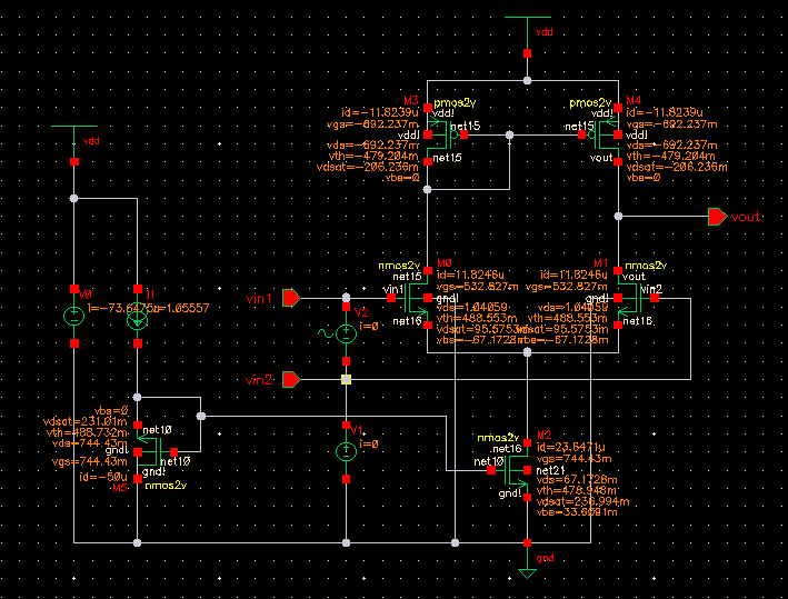
Figure 7. Simulation Schematic of five-tube OTA.
The five-tube OTA has a high input impedance, making it suitable for signal processing with high impedance sources and reducing source loading. Compared to basic current mirrors and general active current mirrors, five-tube OTAs can achieve higher gain and better linearity over small signal ranges, making them suitable for high-precision applications. In addition, five-tube OTAs are typically used for differential signal processing with good common mode rejection. However, higher quiescent currents may be required to achieve the desired performance, increasing power consumption. Due to its complex internal structure and multi-stage amplifier, phase delay and gain roll-off may be introduced, thus requiring frequency compensation to ensure stability. However, all frequency compensation techniques reduce the bandwidth per gain and speed of OTA [12]. In addition to this, both input and output impedances have to be large enough in OTAs [13,14]. Therefore, the design of five-tube OTA is difficult.
However, some studies and literature have reported some of the latest improvements in current mirror OTA. For example, a fully differential recovery scalable common source common gate OTA. In this OTA, additional current mirror OTA and scalable common source common gate OTA are achieved by dividing input transistors [15]. In addition, there are gain boosting techniques for current mirror operational transconductance amplifiers [16], voltage combiner bias single-stage operational amplifiers using current starvation techniques [17], and breakdown voltage combiner bias amplifiers [18].
3.4. Comparison of results
Table 1. Part of the structure simulation results comparison table.
Amplifier Structure | Gain(dB) | Multiple | Bandwidth | Phase margin(deg) | Quiescent dissipation(mW) |
Common source | 27.5162 | 24.94 | 2.503889GHz | 67.9904 | 0.09 |
Sleeve type cascode | 41.6111 | 107.07 | 271.942MHz | -24.9679 | 0.09888 |
Five-Transistor OTA | 44.948 | 175.32 | 5.12052MHz | -51.7763 | 0.1277 |
The simulation was carried out using the process library of tsmc18 in cadence software for the experiments. The three amplifiers are loaded with a 50uA current source, and the vdd is 1.8V. dc and ac scans are performed for the three circuits, and the gain and output curves are obtained by taking the appropriate static operating point. the data analysis in Table1 shows that, without adding external circuits such as a feedback network, the common-source, common-gate and five-tube OTA structures have significant gain improvements compared to the basic common-source amplifier, but their bandwidth and phase margins are unsatisfactory. The gain of the common-gate structure and the five-tube OTA structure is significantly improved compared to the basic common-source amplifier, but its bandwidth and phase margin are very unsatisfactory, and the static power consumption is also increased due to the increase of the MOS tubes.
Therefore, in conjunction with theoretical derivations, the common source, common gate, and five-tube OTA structures help to increase the gain of the amplifier. However, suitable external circuits need to be added to improve other properties such as stability and bandwidth to ensure that the amplifier works properly and is ready for practical applications.
Of course, there are many more methods to increase amplifier gain than the two methods mentioned in this article. Feedback technology is a common method to improve the performance of amplifiers. A flat gain linear low-noise amplifier designed with an improved current reuse structure and feedforward structure was introduced in [19]. Cascade technology is also very commonly used and important. It connects two or more amplifiers in sequence. A low-noise cascaded amplifier for ultra wideband receivers in biosensors was introduced in [20].In addition, using a resistor network or variable resistor can also increase the gain of the amplifier and even adjust the gain. A CMOS based programmable gain operational amplifier was introduced in [21].
4. Conclusion
This report focuses on the reasons for increasing amplifier gain and five common amplifier architectures, and their advantages and disadvantages as well as methods of improvement are comparatively analysed and enumerated through a combination of theoretical derivation and simulation experiments. Sleeved common-source, common-gate amplifiers excel in high-frequency and high-gain applications and are suitable for modern high-speed digital circuits and RF systems. It will continue to play an important role in integrated circuit design as the need for high bandwidth and low power circuits increases. Folded common-source, common-gate amplifiers are suitable for high-performance analogue signal processing and high-precision measurement equipment due to their excellent gain-bandwidth product. This structure will be widely used in high-end analogue circuits and data converters as the requirements for high precision and high frequency performance increase. Basic current mirrors are commonly used in current sources and current amplifiers for low noise and high linearity applications. Current mirror designs will continue to evolve in precision instruments and analogue circuits as the demand for high precision current sources and analogue signal processing increases. Five-tube OTAs offer high transconductance and excellent linearity and are widely used in high-precision analogue circuits and signal processing. As integration increases and the demand for high-performance analog functions increases, five-tube OTAs will play an important role in high-end analogue processing and adaptive filters.
Increasing amplifier gain can also affect linearity, bandwidth, phase margin, power consumption, output swing, and noise. These parameters will constrain each other in practical design, resulting in the design becoming a multidimensional optimization problem. The emphasis on amplifier performance may vary depending on different requirements. For example, audio amplifiers in audio systems require high linearity and low distortion. RF amplifiers in wireless communication devices require wide bandwidth and high gain. Low noise amplifiers in medical sensors require extremely low noise to enhance weak signals. Operational amplifiers in signal conditioning require high precision and adjustable gain. Therefore, it is necessary to design suitable amplifiers for different circuit requirements.
References
[1]. AD8421 2022 High-Precision Instrumentation Amplifier with Low Offset and Low Noise Analog Devices
[2]. ADL5602 2020 A High-Linearity, Wide-Bandwidth RF Amplifier Analog Devices
[3]. INA219 2021 High Side Current Monitor with I2C Interface Texas Instruments
[4]. Paul Horowitz and Winfield Hill 2023 The Art of Electronics Third Edition
[5]. Razavi B 2016 Design of Analog CMOS Integrated Circuits Tsinghua University publishing house co ltd p83
[6]. Yavari M 2022 Advances on CMOS Folded-Cascode Operational Transconductance Amplifier A Tutorial Review, AUT J Elec Eng pp 315-332
[7]. Razavi B 2016 Design of Analog CMOS Integrated Circuits Second Edition Tsinghua University publishing house co ltd p84
[8]. Dheeraj Kalra Vishal Goyal Mayank Srivastava 2023 Low noise amplifier for high-frequency applications: A review, ScienceDirect
[9]. Vikram S Nitin K Manoj K S K A 2022 A common-gate cascaded with cascoded self-bias common source approach for 3.1–10.6GHz UWB low noise amplifier, SpringerLink, p 2389–2398
[10]. Guo B Zhang 2017 An inductor less wideband common-gate LNA with dual capacitor cross-coupled feedback and negative impedance techniques, ScienceDirect, p 53-60
[11]. Lin J 2022, A New Cascode Design with Enhanced Power gain and Bandwidth for Application in mm-Wave Amplifier IEEE 2022 International Symposium on VLSI Technology, Systems and Applications (VLSI-TSA)
[12]. Yavari M 2022 Advances on CMOS Folded-Cascode Operational Transconductance Amplifier A Tutorial Review AUT J Elec Eng pp 315-332
[13]. Carusone T C Johns D A and Martin K W 2012 Analog Integrated Circuit Design Second Edition
[14]. Razavi B 2016 Design of Analog CMOS Integrated Circuits Second Edition Tsinghua University publishing house co ltd
[15]. Mohtashamnia M 2022, A Low-Power LowNoise Neural Recording Amplifier with an Improved Recycling Telescopic-Cascode OTA International Journal of Electronics and Communications no 9 pp 1-11
[16]. Ali S 2015 A power efficient gain enhancing technique for current mirror operational transconductance amplifiers, Micro J no 2 pp 183-190
[17]. Póvoa R Lourenço N Martins R Canelas A Horta N and Goes J 2018 Single-Stage OTA Biased by Voltage-Combiners With Enhanced Performance Using Current Starving IEEE Express Briefs no 11 pp 1599-1603
[18]. Póvoa R A 2020 Folded Voltage Combiners Biased Amplifier for Low Voltage and High Energy Efficiency Applications IEEE Express Briefs no 2 pp 230-234
[19]. Amir H K 2021 Design and analysis of a flat gain and linear low noise amplifier using modified current reused structure with feedforward structure Sci Dire pp 123-136
[20]. Maissa D 2021 A low noise cascaded amplifier for the ultra-wide band receiver in the biosensor Nature Scientific Reports
[21]. Sparsh 2014 Design of CMOS-based Programmable Gain Operational Amplifier RSM 2013 IEEE Regional Symposium on Micro and Nanoelectronics
Cite this article
Xu,R. (2024). A Study of Techniques to Increase Amplifier Gain. Applied and Computational Engineering,103,1-8.
Data availability
The datasets used and/or analyzed during the current study will be available from the authors upon reasonable request.
Disclaimer/Publisher's Note
The statements, opinions and data contained in all publications are solely those of the individual author(s) and contributor(s) and not of EWA Publishing and/or the editor(s). EWA Publishing and/or the editor(s) disclaim responsibility for any injury to people or property resulting from any ideas, methods, instructions or products referred to in the content.
About volume
Volume title: Proceedings of the 2nd International Conference on Machine Learning and Automation
© 2024 by the author(s). Licensee EWA Publishing, Oxford, UK. This article is an open access article distributed under the terms and
conditions of the Creative Commons Attribution (CC BY) license. Authors who
publish this series agree to the following terms:
1. Authors retain copyright and grant the series right of first publication with the work simultaneously licensed under a Creative Commons
Attribution License that allows others to share the work with an acknowledgment of the work's authorship and initial publication in this
series.
2. Authors are able to enter into separate, additional contractual arrangements for the non-exclusive distribution of the series's published
version of the work (e.g., post it to an institutional repository or publish it in a book), with an acknowledgment of its initial
publication in this series.
3. Authors are permitted and encouraged to post their work online (e.g., in institutional repositories or on their website) prior to and
during the submission process, as it can lead to productive exchanges, as well as earlier and greater citation of published work (See
Open access policy for details).
References
[1]. AD8421 2022 High-Precision Instrumentation Amplifier with Low Offset and Low Noise Analog Devices
[2]. ADL5602 2020 A High-Linearity, Wide-Bandwidth RF Amplifier Analog Devices
[3]. INA219 2021 High Side Current Monitor with I2C Interface Texas Instruments
[4]. Paul Horowitz and Winfield Hill 2023 The Art of Electronics Third Edition
[5]. Razavi B 2016 Design of Analog CMOS Integrated Circuits Tsinghua University publishing house co ltd p83
[6]. Yavari M 2022 Advances on CMOS Folded-Cascode Operational Transconductance Amplifier A Tutorial Review, AUT J Elec Eng pp 315-332
[7]. Razavi B 2016 Design of Analog CMOS Integrated Circuits Second Edition Tsinghua University publishing house co ltd p84
[8]. Dheeraj Kalra Vishal Goyal Mayank Srivastava 2023 Low noise amplifier for high-frequency applications: A review, ScienceDirect
[9]. Vikram S Nitin K Manoj K S K A 2022 A common-gate cascaded with cascoded self-bias common source approach for 3.1–10.6GHz UWB low noise amplifier, SpringerLink, p 2389–2398
[10]. Guo B Zhang 2017 An inductor less wideband common-gate LNA with dual capacitor cross-coupled feedback and negative impedance techniques, ScienceDirect, p 53-60
[11]. Lin J 2022, A New Cascode Design with Enhanced Power gain and Bandwidth for Application in mm-Wave Amplifier IEEE 2022 International Symposium on VLSI Technology, Systems and Applications (VLSI-TSA)
[12]. Yavari M 2022 Advances on CMOS Folded-Cascode Operational Transconductance Amplifier A Tutorial Review AUT J Elec Eng pp 315-332
[13]. Carusone T C Johns D A and Martin K W 2012 Analog Integrated Circuit Design Second Edition
[14]. Razavi B 2016 Design of Analog CMOS Integrated Circuits Second Edition Tsinghua University publishing house co ltd
[15]. Mohtashamnia M 2022, A Low-Power LowNoise Neural Recording Amplifier with an Improved Recycling Telescopic-Cascode OTA International Journal of Electronics and Communications no 9 pp 1-11
[16]. Ali S 2015 A power efficient gain enhancing technique for current mirror operational transconductance amplifiers, Micro J no 2 pp 183-190
[17]. Póvoa R Lourenço N Martins R Canelas A Horta N and Goes J 2018 Single-Stage OTA Biased by Voltage-Combiners With Enhanced Performance Using Current Starving IEEE Express Briefs no 11 pp 1599-1603
[18]. Póvoa R A 2020 Folded Voltage Combiners Biased Amplifier for Low Voltage and High Energy Efficiency Applications IEEE Express Briefs no 2 pp 230-234
[19]. Amir H K 2021 Design and analysis of a flat gain and linear low noise amplifier using modified current reused structure with feedforward structure Sci Dire pp 123-136
[20]. Maissa D 2021 A low noise cascaded amplifier for the ultra-wide band receiver in the biosensor Nature Scientific Reports
[21]. Sparsh 2014 Design of CMOS-based Programmable Gain Operational Amplifier RSM 2013 IEEE Regional Symposium on Micro and Nanoelectronics


