


1. Introduction
Residential buildings, office buildings and other multi-storey or high-rise buildings are inseparable from corridor lighting. According to relevant statistics, in the energy consumed by building lighting, the lighting electricity with practical value accounts for about 60% of the total electricity consumption, and the lighting electricity without practical value accounts for about 40% [1]. This is incompatible with the current national policy of energy conservation and environmental protection. Therefore, it is of great practical significance to control the power consumption of corridor lighting reasonably, reduce the power consumption of corridor lighting and save energy.
In order to solve the problem of high electricity consumption in corridor and residential area lighting, with the development of lighting equipment in recent years, LED has gradually replaced the incandescent lamp for lighting because of its significant advantages such as environmental protection, long life, high photoelectric efficiency, and low production cost, and other components are added to realize sound and light double control [2-4]. In the field of new energy, solar energy, as a green renewable energy, has the advantages of large reserves, economic use, cleanliness and environmental protection [5]. Access to solar energy has become economically feasible, and the coverage is large and can be widely popularized in the world. Therefore, combined with solar cells of the corridor lighting system has a certain practical value [6]. Due to the high reliability of the programmable controller (referred to as PLC) (the average trouble-free time can reach 8-100,000 hours), simple programming, strong versatility, small size, compact structure, easy installation and maintenance. It can be used to reduce energy waste in manual control, ensure the stability and reliability of control, and take electronic technology to control the lighting circuit [7-8].
In this paper, LED lighting components and an Arduino-UNO development board are selected to build a simple voice-controlled and light-sensitive lighting system, and relevant programs are written on Arduino software to verify and realize the functions of lighting and energy saving. The reliability of PLC is verified, and the problems of lighting convenience and energy saving in real life are solved.
2. Case basis
The rapid development of computer technology drives the breakthrough of speech recognition technology, and the increasingly powerful voice control system is gradually applied in real life. In a study using LD3320 speech recognition chip, fast response, and high recognition rate, the system combined STC11L08XE single chip and peripheral circuit and nRF24L01 wireless transmission chip to carry out the overall structure of the voice control light system and each module hardware selection and program writing [9]. The static test of the function of the voice control light system is completed based on the non-specific person, that is, the training and recognition object of the non-specific person are oriented to the public, and the recognition rate is close to 95%.
Another study using the micro-power characteristics of MK6A11P, an LED light with micro-power consumption, acoustic-optical control and high sensitivity is designed [10]. It has < 0.1 W standby power consumption and high sensitivity, which overcomes the problem that the sensitivity of the existing voice control lamp is too low. At the same time, it solves the phenomenon of steady on when the voice control sensitivity is high. It can be widely used in public places where the crowd flow is more random, such as corridors, elevator doors, public toilets and so on.
3. Experiment
3.1. Methodology
In order to verify the functional perfection of the simple voice-controlled and light-sensitive LED lighting system designed to meet the basic lighting needs in daily life scenes, this paper designs 5 different scenes, simulates different situations in real life, and observes whether the LED lights are lit to verify the integrity of the program and functions. The first scene is the initialization state when dawn and the environment has no sound. The second scene is dark but the environment has no sound. The third scene is dawn and the environment has sound, the fourth scene is dark and the environment has sound, and the last one is to restore the initialization.
3.2. Process
Figure 1 is the overall design block diagram of the lighting system.
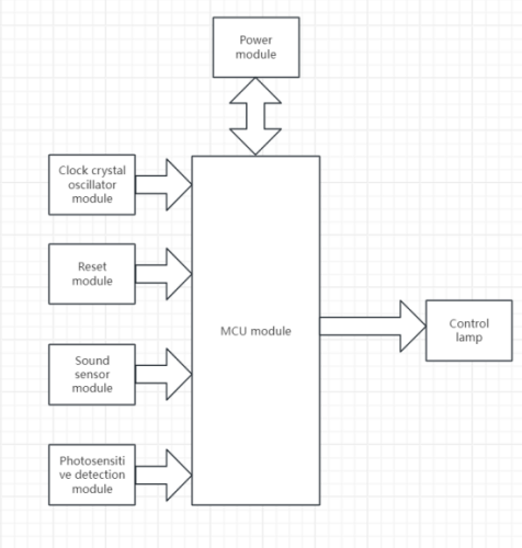
Figure 1. System structure block diagram
As shown in Figure 2, the system is composed of two parts, the sensor part on the far left, and the controller part on the right. The sensor part is composed of a sound sensor and a light sensor, and the controller part is composed of an Arduino-UNO core board and an LED lamp control circuit. The whole system is powered by the computer through the USB data cable.
Processor is the core of the whole system, different application fields, different user needs, and the choice of processor is diversified. Since the sound and light control lighting built in this paper is not complicated, a relatively basic Arduino-UNO, which is a microcontroller board based on ATmega328P, was chosen. It has 14 digital input/output pins (6 of which can be used as PWM outputs), 6 analog inputs, a 16MHz crystal clock, a USB connection, a power jack, an ICSP connector, and a reset button. You only need to connect the computer through the USB cable to power, program download and data communication. And Figure 2 shows the main pins of the Arduino-UNO core board.
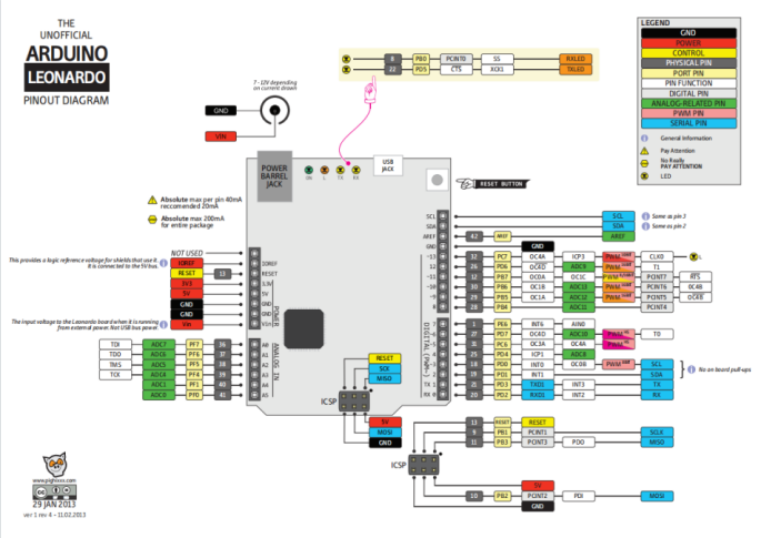
Figure 2. Pin distribution diagram
The Arduino-UNO is powered by USB or a 5V-12V external power supply and uses 5V pins to supply power to the rest of the system modules. In this system, the A2 port is set to collect the analog data of the sensor, the digital data of the sensor is collected through the digital input interface on the right, and the output control level of the digital output port is controlled after the processor and program operation.
The sound sensor uses the YL-56 sensor. It can detect the intensity of sound in the surrounding environment, but this sensor can only identify the presence or absence of sound (according to the principle of vibration), not the size of the sound or the specific frequency of sound. Its sensitivity can be adjusted by a digital potentiometer, operating at 3.3V-5V. The output form is a digital switching output (0 and 1 high and low levels). Its small PCB size is 3.4cm x 1.6cm. When the ambient sound intensity of the module does not reach the set threshold, the D0 port outputs a high level; when the ambient sound intensity exceeds the set threshold, the D0 port outputs a low level; The digital output D0 of the small board is directly connected to the single chip microcomputer, and the level is detected by the single chip microcomputer, so as to determine whether the sound of the environment is there.
The light detection module adopts a four-wire photoresistor sensor. Using a sensitive photoresistor sensor, and a wide voltage LM393 comparator output, the signal is clean, the waveform is good, and the driving capacity is strong, more than 15mA. The potentiometer can be applied to adjust the brightness of the detection light.
In order to reduce the overall energy consumption of the system, light-emitting diodes (LEDs) are selected as lighting tools. The energy consumption of LED lights is one-tenth of that of incandescent lamps and one-fourth of energy-saving lamps, and as long as the power is turned on, the LED lights will light up immediately. Compared with the energy-saving lamps we usually use, the reaction speed is faster, when opening the traditional light bulb, it often takes a long time to illuminate the room, and after the lamp is thoroughly heated, it can be lit up. And LED lights can be high-speed switching work. If the number of switches is too many, it will directly lead to incandescent filament breakage, and LED lights can adapt to the changing working environment, by several LED lighting systems. A single LED light out will not lead to the overall replacement.
As for the control circuit of the lamp, this paper uses a triode to realize the control of the light on and light off. By binding the base to the digital output port of the core board, you can control the lighting of the LED light. When the base voltage is low, the circuit can be switched on and the light turned on.
The system program is modularized by C language under the Arduino software development environment. The workflow includes system initialization, port setup, data acquisition, identification comparison and output.
When the single-chip microcomputer is powered on, the system software will initialize the whole, which includes defining the pins connecting the sensor module and the control circuit, initializing the serial communication, and specifying the input and output of the pins.
Because the photoresistor sensor can collect the analog quantity of the environment, to determine an accurate threshold for subsequent identification and comparison, convert the value range of the analog quantity collected from 0 to 1023 to 0 to 10, and display it on the serial port monitor. The simulated values displayed in full light and dark light environments are collected respectively, and the appropriate intermediate value is selected as the metric value to distinguish the two situations by adjusting the potentiometer, so as to select the conditional judgment of the light intensity in the comparison process. And the sound sensor settings are the same.
All modules are fixed and connected by DuPont wire and breadboard. The initial state of the LED is off. After the execution of the initial instruction, the system will collect the analog quantity of the photoresistor sensor and carry out the numerical conversion. When the analog quantity of the collected light intensity is greater than the set value, the program will judge whether there is any environmental sound. When the input level of the sound sensor is a high power level, the 2-port of the core board outputs a low level connects the LED lighting circuit, and the LED light is on and carries out cyclic detection. When any of the above conditions are not met, pin 2 turns to the output high level after a 5s delay.
3.3. Code
The code added to the Arduino-UNO core board is shown below.
int photoPin= A2;
void setup(){
pinMode(photoPin,INPUT);
pinMode(2, OUTPUT);
pinMode(3, INPUT);
pinMode(4, INPUT);
Serial.begin(9600);
}
void loop(){
pinMode(3, INPUT);
pinMode(4, INPUT);
int lightRaw = analogRead(photoPin);
int light = map(lightRaw, 1023, 0, 10, 0);
Serial.println(light);
digitalWrite(2,HIGH);
if (digitalRead(3) == HIGH && light > 5) {
digitalWrite(2,LOW);
delay(5000);
digitalWrite(2,HIGH);
}
}
3.4. Results
After the integrity test of each module of the system, the whole system is assembled according to the design circuit diagram, and the code is transmitted for the experiment.
A total of 5 simulation scenarios were set up in the experiment. The first scenario is during the day with no noise in the environment, and at this time the system is in the initial state. The switch indicator of the photoresistor sensor remains on, the switch indicator of the sound sensor remains off, and the LED remains off. In the second and third scenarios, there is a condition that is not satisfied, that is, the environment has no sound or the light intensity is high, the photoresistor sensor and the sound sensor cannot meet the conditions at the same time, and the LED lamp remains out. In the fourth scene, when darkness and ambient sound are detected, the analog value collected by the photoresistor sensor is greater than the set threshold, and the sound sensor responds to the ambient sound. Pin 2 outputs a low level, switches on the control circuit, and the LED lights up. When any condition of the fourth scenario is no longer met, the system starts the delay lights out program, and after a delay of a certain time, pin 2 outputs a high level, and the LED is extinguished. Table 1 shows the state changes of LED lights in different scenarios.
Table 1. The states of LED lights in different scenarios
Day/Night | Presence or absence of sound | Initial state of LED | State of LED |
Day | Absence | OFF | OFF |
Day | Presence | OFF | OFF |
Night | Absence | OFF | OFF |
Night | Presence | OFF | ON |
Night | Absence | ON | Go off after a few seconds |
Day | Presence | ON | Go off after a few seconds |
This system is only a simple simulation and experiment of the daily use of the corridor lighting system. It currently only has the function of lighting and delaying lights out according to the sound and lighting conditions. In the future, we will consider adding solar charging and discharging equipment inside the system to realize the utilization of clean energy. Continuously optimize lighting and sensor equipment to improve energy utilization. At the same time, the composite system connected with infrared detection and ultrasonic detection devices will be deeply studied to achieve accurate detection of people and things, improve the sensitivity of the system, and further achieve the goal of energy saving and lighting.
4. Conclusion
This paper studies the design of the daily corridor and residential district lighting system, builds a simple acousto-optical lighting device based on the Arduino platform, and realizes the purpose of lighting and energy saving through the design of corresponding programs. In the experiment, multiple simulation scenarios are designed to verify the integrity of its functions, achieving the design goal and having certain practical value. However, due to the relatively simple components purchased at this stage, the accurate measurement of the ambient light and sound size cannot be achieved, so the threshold triggered by the sensor cannot be accurately adjusted according to actual needs. In the future, sensor components will be replaced as needed to achieve accurate acquisition of light and sound. The function of speech recognition is added to the system, and corresponding program modules are designed to realize different lighting modes according to different voice commands. Consider adding infrared or ultrasonic recognition modules to realize advanced identification of people and further facilitate the lives of residents. With the continuous development of lighting systems and the continuous improvement of programmable technology, the design and system in this area will be more perfect and energy-saving.
References
[1]. Tian Yi. Corridor lighting control system review [J]. Journal of electronics, 2017, (6) : 29. 27 + DOI: 10.16589 / j.carol carroll nki cn11-3571 / tn. 2017.06.014.
[2]. Ren Tao. LED the discussion of functional lighting advantage [J]. Modern manufacturing technology and equipment, 2021,57 (6) : 174-175. The DOI: 10.16107 / j.carol carroll nki mmte. 2021.0500.
[3]. Wu Shunhua. Converting Incandescent Lamps to LEDs with Sound and Light Control [J]. Electronic Making, 2014, (09): 19-20. DOI: 10.16589/j.cnki.cn11-3571/tn.2014.09.047.
[4]. Pulli T ,Dönsberg T ,Poikonen T , et al.Advantages of white LED lamps and new detector technology in photometry[J].Light: Science & Applications,2015,4(8):e332-e332.
[5]. Tian Haitao, Yang Wenting. Solar light fiber technology in the application of lighting [J]. Science and technology innovation herald, 2020 (10) : 14 + 16. DOI: 10.16660 / j.carol carroll nki. 1674-098 - x. 2020.10.014.
[6]. Shao Yunlian. Design of Solar Corridor Induction Delay Lighting [J]. Industry & Technology Forum,2013,12(24):60-61.
[7]. Chen Qingbin. Residential lighting intelligent control [J]. Journal of electronics, 2009, (8) : 50-54 + 1. DOI: 10.16589 / j.carol carroll nki cn11-3571 / tn. 2009.08.018.
[8]. LU Shungao. Design of acousto-optic control lighting Circuit based on Electronic Technology [J]. Light Source and Lighting,2022,(12):115-117.
[9]. Jiang JW, Jiang YJ, Bing Xiaohuan, et al. Speaker-independent recognition based on LD3320 voice control lamp system design [J]. Journal of modern electronic technology, 2015, 38 (11) : 27 to 30, DOI: 10.16652 / j.i SSN. 1004-373 - x. 2015.11.022.
[10]. Kim Youngho, Kim Jeol. Micro power consumption of high sensitivity to sound and light control type LED light design [J]. Journal of electronic science and technology, 2012, 25 (3) : 66-68. The DOI: 10.16180 / j.carol carroll nki issn1007-7820.2012.03.006.
Cite this article
Jiang,F. (2024). Simple Light-sensitive and Voice-controlled Lighting System based on Arduino. Applied and Computational Engineering,109,63-68.
Data availability
The datasets used and/or analyzed during the current study will be available from the authors upon reasonable request.
Disclaimer/Publisher's Note
The statements, opinions and data contained in all publications are solely those of the individual author(s) and contributor(s) and not of EWA Publishing and/or the editor(s). EWA Publishing and/or the editor(s) disclaim responsibility for any injury to people or property resulting from any ideas, methods, instructions or products referred to in the content.
About volume
Volume title: Proceedings of the 2nd International Conference on Machine Learning and Automation
© 2024 by the author(s). Licensee EWA Publishing, Oxford, UK. This article is an open access article distributed under the terms and
conditions of the Creative Commons Attribution (CC BY) license. Authors who
publish this series agree to the following terms:
1. Authors retain copyright and grant the series right of first publication with the work simultaneously licensed under a Creative Commons
Attribution License that allows others to share the work with an acknowledgment of the work's authorship and initial publication in this
series.
2. Authors are able to enter into separate, additional contractual arrangements for the non-exclusive distribution of the series's published
version of the work (e.g., post it to an institutional repository or publish it in a book), with an acknowledgment of its initial
publication in this series.
3. Authors are permitted and encouraged to post their work online (e.g., in institutional repositories or on their website) prior to and
during the submission process, as it can lead to productive exchanges, as well as earlier and greater citation of published work (See
Open access policy for details).
References
[1]. Tian Yi. Corridor lighting control system review [J]. Journal of electronics, 2017, (6) : 29. 27 + DOI: 10.16589 / j.carol carroll nki cn11-3571 / tn. 2017.06.014.
[2]. Ren Tao. LED the discussion of functional lighting advantage [J]. Modern manufacturing technology and equipment, 2021,57 (6) : 174-175. The DOI: 10.16107 / j.carol carroll nki mmte. 2021.0500.
[3]. Wu Shunhua. Converting Incandescent Lamps to LEDs with Sound and Light Control [J]. Electronic Making, 2014, (09): 19-20. DOI: 10.16589/j.cnki.cn11-3571/tn.2014.09.047.
[4]. Pulli T ,Dönsberg T ,Poikonen T , et al.Advantages of white LED lamps and new detector technology in photometry[J].Light: Science & Applications,2015,4(8):e332-e332.
[5]. Tian Haitao, Yang Wenting. Solar light fiber technology in the application of lighting [J]. Science and technology innovation herald, 2020 (10) : 14 + 16. DOI: 10.16660 / j.carol carroll nki. 1674-098 - x. 2020.10.014.
[6]. Shao Yunlian. Design of Solar Corridor Induction Delay Lighting [J]. Industry & Technology Forum,2013,12(24):60-61.
[7]. Chen Qingbin. Residential lighting intelligent control [J]. Journal of electronics, 2009, (8) : 50-54 + 1. DOI: 10.16589 / j.carol carroll nki cn11-3571 / tn. 2009.08.018.
[8]. LU Shungao. Design of acousto-optic control lighting Circuit based on Electronic Technology [J]. Light Source and Lighting,2022,(12):115-117.
[9]. Jiang JW, Jiang YJ, Bing Xiaohuan, et al. Speaker-independent recognition based on LD3320 voice control lamp system design [J]. Journal of modern electronic technology, 2015, 38 (11) : 27 to 30, DOI: 10.16652 / j.i SSN. 1004-373 - x. 2015.11.022.
[10]. Kim Youngho, Kim Jeol. Micro power consumption of high sensitivity to sound and light control type LED light design [J]. Journal of electronic science and technology, 2012, 25 (3) : 66-68. The DOI: 10.16180 / j.carol carroll nki issn1007-7820.2012.03.006.