


1. Introduction
With the rapid advancement of automation technology, robot tracking and navigation has demonstrated extensive application prospects across various sectors, including industry, agriculture, and service industries. Although this technology boasts fast processing speed, excellent scaling, and good rotational properties, it exhibits a significant dependence on initial conditions, texture, and other factors[1].Subsequently, Bescos and other researchers developed DynaSLAM based on ORB-SLAM2,which is a SLAM technique specifically designed to handle dynamic situations and can also be used to detect dynamic objects in scenes[2].In recent years, Yuan Yin and his team have proposed a SLAM algorithm based on YOLOv5, aiming to enhance its mapping capabilities by specifically recognizing dynamic objects[3].
This article primarily explores a robot tracking and navigation method based on visual SLAM. This method utilizes environmental information captured by cameras for real-time positioning and map building, guiding the robot to follow a predetermined trajectory.
Firstly, the basic principles of tracking and navigation technology were introduced, including how sensors perceive path markings, how control systems process data, and how actuators adjust the direction of the robot's travel. Subsequently, the article delved into the key components of visual SLAM systems, analyzing feature point extraction, map construction, and optimization strategies.
In addition, the article also discusses the challenges faced by visual SLAM in practical applications, such as real-time performance, robustness, and error accumulation, and proposes strategies to overcome these challenges through sensor fusion and algorithm optimization. The target of this article is to offer fresh perspectives and solutions for advancing robot tracking and navigation technology.
2. Principles of tracking navigation technology
Tracking navigation technology is a technique that enables robots or vehicles to automatically travel along a predetermined path. Its basic principle includes four key steps. Firstly, sensing devices such as infrared sensors, photoelectric sensors, or cameras are used to detect marking lines or other specific markers on the ground. These sensors can sense the position and direction of the marking lines, providing a basis for the device's driving direction. Next, the data collected by the sensors will be transmitted to the control system for processing. The control system will analyze this data based on preset algorithms and logic to determine the current position and direction of the device, as well as whether it is necessary to adjust the driving direction. And then design the tracking navigation algorithms, commonly including PID control algorithms, neural network algorithms, etc., which help devices achieve precise tracking effects.These algorithms are supposed to be able to handle sensor noise and adjust control strategies in a timely manner based on environmental changes. Finally, based on the results of data processing, the steering and speed of the equipment are adjusted through actuators such as motors or servos to ensure that the equipment can travel along the predetermined path.
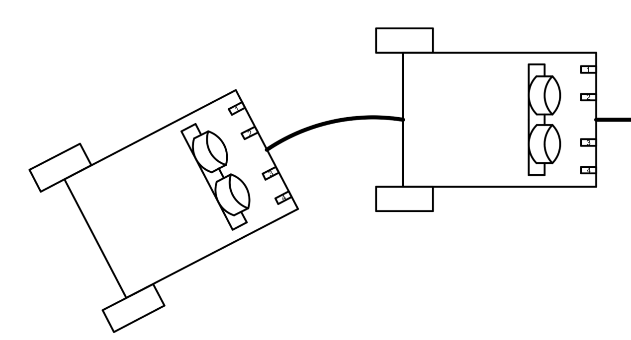
Figure 1. Traditional tracking car model.
As shown in Figure 1, most of the existing tracking car systems use three infrared tracking sensors to achieve tracking function, with detection distances ranging from 0 to 2 to 3cm. This module is equipped with an infrared transmitter and receiver on the car. The infrared emitter, which are used to receive infrared light reflected back from the ground, generates an infrared beam that illuminates the trajectory on the ground. which are used to receive infrared light reflected back from the ground. During the operation of the car, black lines or other high contrast trajectories on the ground can better absorb and reflect infrared light. The infrared receiver in the tracking module can detect this reflection, while the reflection is stronger in areas outside the trajectory. When the infrared receiver receives reflected infrared light, the voltage signal generated by it will change accordingly based on the different reflection abilities of black and white colors. The change in voltage signal is related to the current position of the car relative to the trajectory. According to the voltage signal generated by the infrared receiver, the tracking module can determine the position of the car relative to the trajectory. From Figure 2, It shows the tracking principle of the car. If the sensor on the left perceives strong reflection and the sensor on the right perceives weak reflection, it indicates that the sensor on the right has detected a black line. The system may determine that the car is leaning towards the left side of the trajectory and adjust the speed of the car's wheels to make the speed of the right wheel smaller than that of the left wheel. For example, if the right wheel slows down and the left wheel accelerates. So as to adjust the direction of the car to the left and return to the track, and vice versa. This information is provided to the controlling system to adjust the direction of the car, keeping it on the predetermined path, and stopping for inspection if other special situations occur. The tracking module plays a crucial role in the tracking and obstacle avoidance of cars, enabling them to autonomously travel in complex environments and follow predetermined tracks[4].
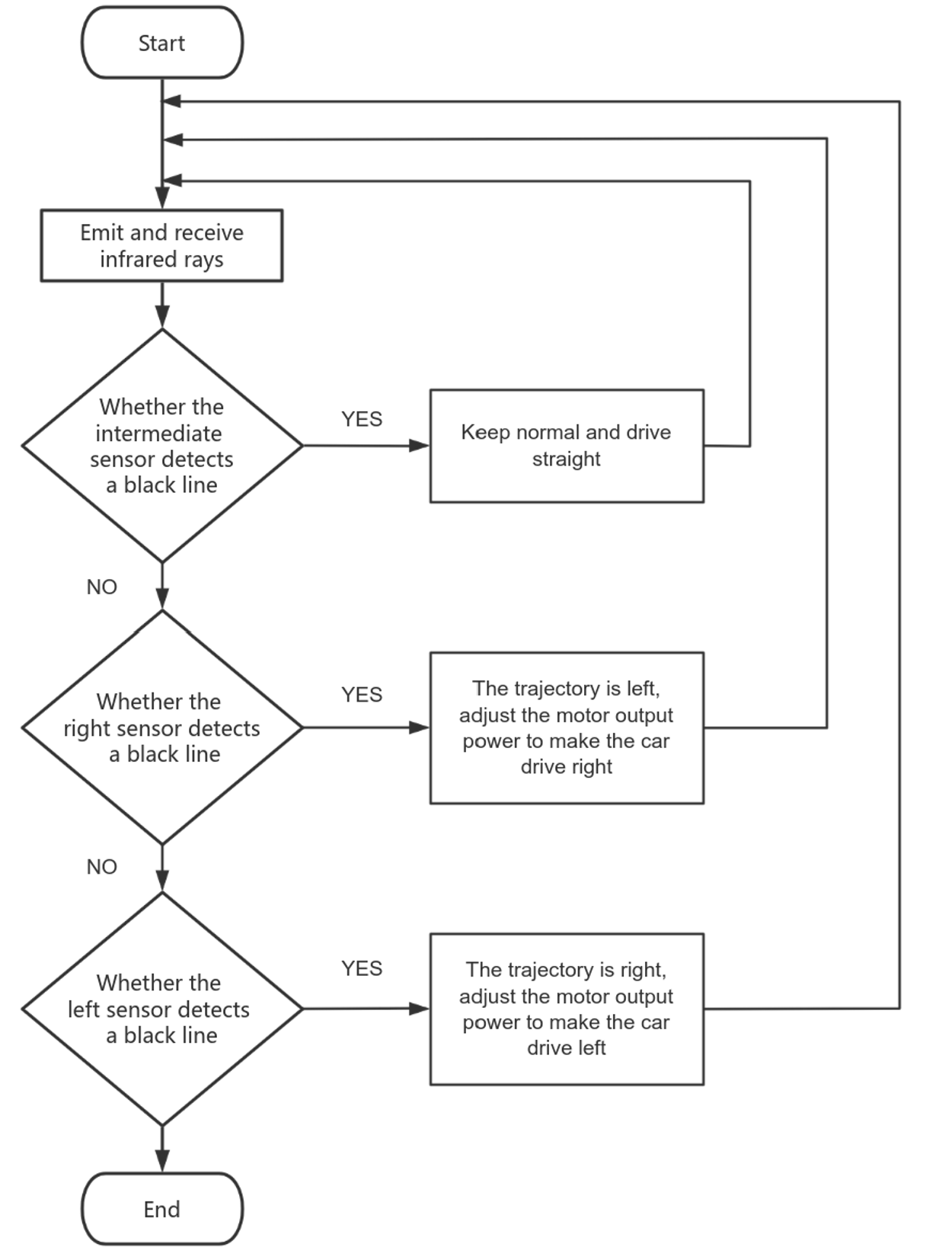
Figure 2. Flow chart of tracking car
3. Tracking navigation method based on visual SLAM
The SLAM system framework is roughly divided into three modules, as shown in Figure 3: visual odometry, local map mapping, and global optimization module.
The frontend of V-SLAM is to process the input image and obtain the motion relationship while the camera moves to determine the position of the current frame[5]. It mainly contains two parts, namely a visual sensor and a visual odometer. The visual sensor is responsible for reading and preprocessing the camera image information. The visual odometer estimates the camera movement based on the data from adjacent images to provide a better initial value for the backend[6].
With advances in computer technology, visual sensors have significantly improved in resolution, pixels, and focus. According to different working methods, these are divided into monocular, stereo, and RGB-D (Red Green Blue-Depth) cameras [7]. The monocular camera has a simple structure and fast calculation speed but lacks the depth of information and has scale blur [8]. Stereo cameras can obtain depth information indoors or outdoors through the four steps of calibration, correction, matching, and calculation, but the amount of computation needed is significant. RGB-D cameras have become popular in the last ten years [9,10] because they can obtain image color and depth information at the same time [11].
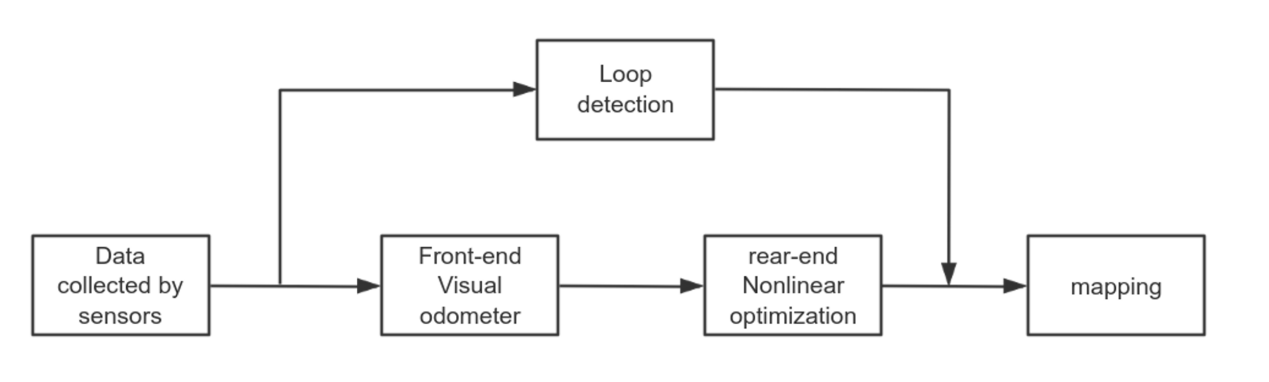
Figure 3. Basic modules of visual SLAM
3.1. Tracking navigation framework
As shown in Figure 4, this article references the framework of visual SLAM technology in Mr. Luo Hai's article. In this framework, the feature point method was chosen instead of the direct method as the visual front-end algorithm because the direct method has low accuracy and relies on GPU accelerated optical flow processing, which some hardware cannot meet the requirements.Selecting ORB features as feature points, robust feature matching method is adopted for feature matching and data association, which improves the speed of 2D-3D data association while meeting the accuracy requirements.Due to the use of ORB feature points, the backend adopts the DOW2 bag of words model based on ORB features for loop detection, improving the trajectory’s robustness and enhancing feature data utilization. In the backend optimization part, low computational pose map optimization is adopted in the local map to improve the accuracy of the local map in real-time. Every second, further graph optimization is performed on the global map to construct a sufficiently accurate global map [12].
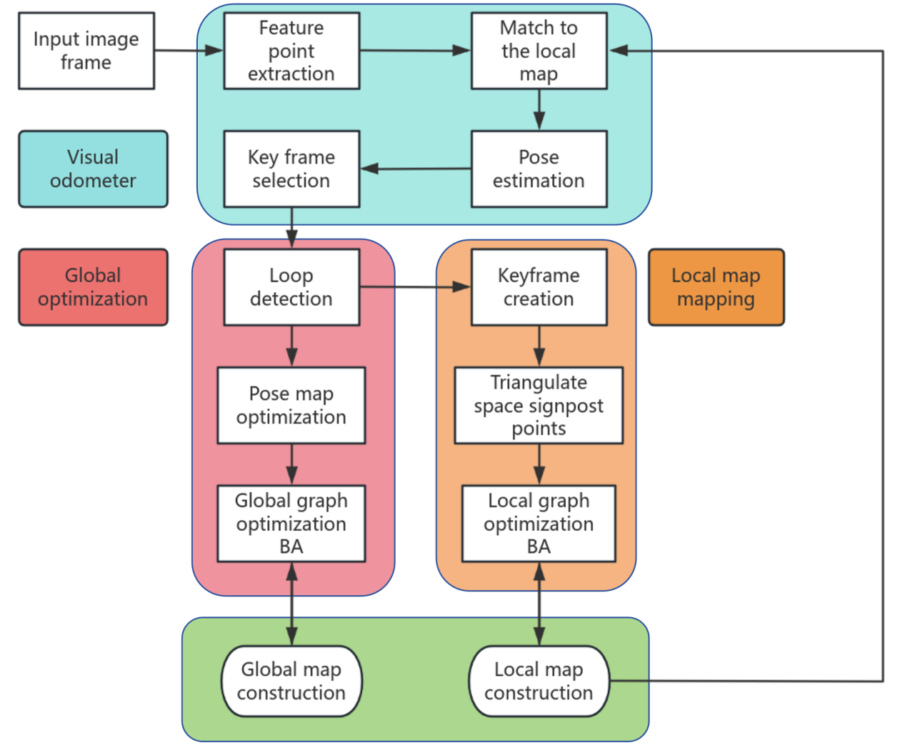
Figure 4. VSLAM system framework selected
3.2. Visual SLAM technology can be applied to tracking navigation through the following steps
The approximate overall framework is shown in the figure 5. Firstly, the feature extraction of the image is carried out. The visual SLAM system uses cameras installed on the robot to capture environmental images and extract feature points from them. These feature points can be visual features such as wall corners, ground textures, object edges. Then real-time positioning is performed, and by matching with the feature points in the previously constructed map, the visual SLAM system can estimate the robot's position and posture in real time. This step typically involves feature matching and motion estimation algorithms. Afterwards, while positioning, mapping is carried out, and the visual SLAM system constructs or updates the map of the environment. During this process, the system will record the spatial positions of feature points, forming a three-dimensional map of the environment. Based on the formed map combined with the positioning information and map data provided by visual SLAM, a tracking navigation system can be used to plan and adjust the robot's path, allowing it to autonomously navigate along a preset trajectory or avoid obstacles.
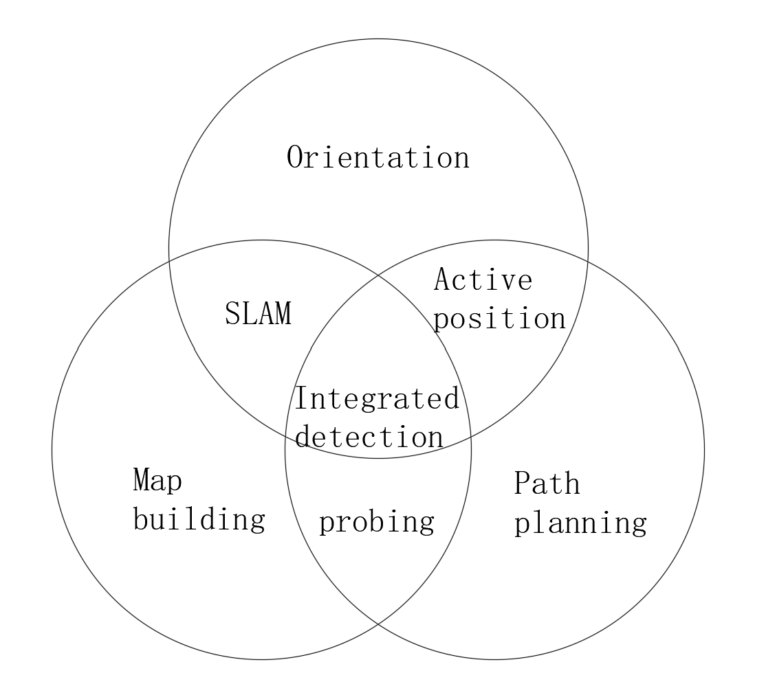
Figure 5. Application of SLAM technology in tracking navigation
In autonomous navigation, closed-loop detection is also necessary: during movement, the visual SLAM system can detect the robot returning to a previously known position (closed-loop), which helps improve the accuracy and robustness of navigation. The advantage of using this technology in navigation is that it does not require external sensors such as magnetic stripes or QR codes, and can directly utilize natural features in the environment for localization and mapping. This makes it suitable for diverse environments and can provide more flexible and intelligent navigation solutions. In practical applications, visual SLAM can be combined with tracking navigation algorithms to improve the adaptability and autonomous navigation ability of robots in dynamic environments.
4. Discussion
4.1. Advantages and disadvantages of visual SLAM navigation
Visual SLAM is a real-time environment perception algorithm [13] that can use cameras to achieve simultaneous localization and map construction. In visual SLAM, the working modes of cameras can be divided into three types: monocular, binocular, and depth cameras (RGB-D), and their advantages and disadvantages are shown in Table 1 [14].
Table 1. Common visual sensors
Camera type | advantage | disadvantage |
Monocular camera | The camera is low cost, simple hardware, easy to deploy, and relatively small compared to others. | The depth information can not be obtained directly, which leads to the scale uncertainty, and the depth needs to be estimated by triangulation in motion. It requires a large amount of computation and has certain requirements for computing resources. |
Binocular camera | The depth can be estimated by parallax to provide more abundant 3D information. Depth can be estimated either in motion or at rest. | It requires a lot of computation to deal with image feature matching and parallax calculation. It has certain requirements for ambient lighting and texture, and performs poorly in environments with large lighting changes or lack of texture. Configuration and calibration are complicated. |
RGB-D camera | The depth information can be obtained directly, which simplifies the depth estimation process. Provides accurate 3D maps suitable for indoor environments. | The measuring range is limited, usually limited by the range; May be disturbed by ambient light; Performance may be limited in outdoor environments; The field of view is relatively small. |
The accuracy of algorithm positioning is easily affected by external factors such as changes in light and rapid changes in the field of view. Therefore, relying solely on a single camera sensor is difficult to achieve accurate positioning and mapping simultaneously. Due to the fact that IMU (Inertial Measurement Unit) is a typical self-sensing sensor, it is suitable for computing the short and fast movements of mobile robots, and there is good complementarity between IMU and camera sensors. Therefore, the fusion of cameras and IMU sensors can effectively solve the above problems and improve the stability of the algorithm. As a result, the visual-inertial SLAM algorithm has gradually attracted people's attention [15,16].
However, the application of visual SLAM in tracking navigation still faces some challenges, including real-time issues, which require algorithms to efficiently process large amounts of image data to provide real-time positioning and map information. The next step is how to improve robustness, as the system needs to operate under changing environmental conditions such as lighting changes, dynamic object interference, and texture loss. This requires the algorithm to have sufficient robustness to cope with these complex scenes. There is also a problem of error accumulation. Due to model bias, visual SLAM systems may gradually accumulate errors in the absence of external information. Therefore, it is necessary to reduce this accumulation of errors through backend optimization and loop detection.
4.2. Feasibility plan for SLAM navigation
How to improve the robustness of SLAM navigation can be achieved by combining various sensor data (such as LiDAR, IMU, etc.) for data fusion, in order to enhance its robustness in dynamic environments and lighting changes. In addition, more advanced feature detection methods can also be used, or the algorithm can be trained adaptively for specific environments. For challenging scenarios such as high dynamic scenes, weak textures, motion blur, and repetitive textures, where feature point tracking errors or failures are difficult, there is already an adaptive feature matching and recognition algorithm that tightly couples visual-inertial navigation. In the framework based on nonlinear optimization, IMU measurement values predict the state, and the algorithm adaptively predicts potential matching pairs based on the number of tracking feature points or removes erroneous matching pairs based on epipolar geometry, resulting in high feature point tracking length and accuracy. In weak texture and motion blur environments, it can increase the number of correct feature matching pairs, and effectively eliminate erroneous matching pairs in high dynamic and repetitive texture environments. Finally, the algorithm will be introduced into the VINS system to evaluate the effectiveness of feature matching and adaptive recognition algorithms for high positioning accuracy in challenging scenarios[17].
5. Conclusion
Visual SLAM technology can improve the autonomous navigation capability of machinery in tracking navigation, especially in complex indoor environments. This technology can assist robots in precise positioning and map construction, enabling autonomous navigation and reducing reliance on manual operations. For example, visual SLAM can be used to navigate service robots, enabling them to move autonomously in the environment, improving service efficiency and reducing the risk of accidents. In addition, visual SLAM technology can also be applied to the navigation of capsule robots. By combining deep learning and SLAM technology, the detection and recognition ability of capsule robots in the gastrointestinal tract can be improved, and the patient's internal condition can be reflected before surgery, thereby improving the accuracy of diagnosis. Visual SLAM technology may provide more precise and comprehensive effects and the potential to improve the performance of medical machinery in the future.
In the future, visual SLAM technology may be further integrated with deep learning. Improve the robustness and accuracy of this technology through more advanced and effective neural networks. It is also possible to significantly improve the computational efficiency of this technology through better algorithms, making it applicable to more scenarios that require short-term strain. In addition, hardware improvements may also significantly enhance the performance of SLAM technology.
References
[1]. Mur-Artal R and Tardós J D 2017 ORB-SLAM2 an open-source SLAM system for monocular, stereo and RGB-D cameras IEEE Trans Robot vol 33 pp 1255–1262
[2]. Bescos B 2018 DynaSLAM tracking, mapping, and inpainting in dynamic scenes IEEE Robotics and Automation Letters vol 3 no 4 pp 4076-4083
[3]. Yuan Y Yang S Chen M 2024 Dynamic scenarios YOLOv5 based SLAM algorithm Journal of Chongqing University pp 1-9
[4]. Song Y Guo Z Zhang F et al 2024 Intelligent tracking based on STM32 obstacle avoidance car research Computer programming skills and maintenance vol 8 pp 114-117
[5]. Jia G Li X Zhang D Xu W Lv H Shi Y Cai M 2022 Visual-SLAM Classical Framework and Key Techniques: A Review. Sensors vol 22 no 12 pp 4582
[6]. Nister D Naroditsky O Bergen J R Visual odometry 2004 In Proceedings of the IEEE Computer Society Conference on Computer Vision Pattern Recognition
[7]. Huang B Zhao J Liu J 2019 A Survey of Simultaneous Localization and Mapping with an Envision in 6G Wireless Networks
[8]. Liu H Zhang G Bao H 2016 A Survey of Monocular Simultaneous Localization and Mapping J Comput.Aided Des Comput Graph vol 28 no 8 pp 55–868
[9]. Khoshelham K Elberink S O 2012 Accuracy and Resolution of Kinect Depth Data for Indoor Mapping Applications Sensors vol 12 pp 1437
[10]. Henry P Krainin M Herbst E Ren X Fox D 2014 RGB-D Mapping: Using Depth Cameras for Dense 3D Modeling of Indoor Environments Exp Robot vol 79 pp 477–491
[11]. Grisetti G Kümmerle R Strasdat H Konolige K G 2011 A general Framework for (Hyper) Graph Optimization. In Proceedings of the 2011 IEEE International Conference on Robotics and Automation, Shanghai, China pp 3607–3613
[12]. Chi S 2020 SLAM technology research and application based on vision Jianghan University
[13]. Cui L 2023 SLAM Problem of mobile robot based on vision and inertial navigation integration in dynamic scenes Guangxi university of science and technology
[14]. Cheng J Zhang L Chen Q et al 2022 A review of visual SLAM methods for autonomous driving vehicles Engineering Applications of Artificial Intelligence vol 114 pp 104992
[15]. Si Sh Zhao D Xu W et al 2021 Research progress of vision-inertial navigation and positioning technology Journal of Image and Graphics vol no 6 26 pp 1470-1482
[16]. Zhou J Ji Ch 2002 Multi-sensor fusion technology in autonomous vehicle navigation systems Transactions of the Chinese Society for Agricultural Machinery vol 05 pp 113-116+133
[17]. Yu Z 2002 Based on visual intelligent vehicle positioning of inertial fusion technology research University of electronic science and technology.
Cite this article
Sun,W. (2024). Robot Tracking Navigation Based on Visual SLAM. Applied and Computational Engineering,111,183-190.
Data availability
The datasets used and/or analyzed during the current study will be available from the authors upon reasonable request.
Disclaimer/Publisher's Note
The statements, opinions and data contained in all publications are solely those of the individual author(s) and contributor(s) and not of EWA Publishing and/or the editor(s). EWA Publishing and/or the editor(s) disclaim responsibility for any injury to people or property resulting from any ideas, methods, instructions or products referred to in the content.
About volume
Volume title: Proceedings of CONF-MLA 2024 Workshop: Mastering the Art of GANs: Unleashing Creativity with Generative Adversarial Networks
© 2024 by the author(s). Licensee EWA Publishing, Oxford, UK. This article is an open access article distributed under the terms and
conditions of the Creative Commons Attribution (CC BY) license. Authors who
publish this series agree to the following terms:
1. Authors retain copyright and grant the series right of first publication with the work simultaneously licensed under a Creative Commons
Attribution License that allows others to share the work with an acknowledgment of the work's authorship and initial publication in this
series.
2. Authors are able to enter into separate, additional contractual arrangements for the non-exclusive distribution of the series's published
version of the work (e.g., post it to an institutional repository or publish it in a book), with an acknowledgment of its initial
publication in this series.
3. Authors are permitted and encouraged to post their work online (e.g., in institutional repositories or on their website) prior to and
during the submission process, as it can lead to productive exchanges, as well as earlier and greater citation of published work (See
Open access policy for details).
References
[1]. Mur-Artal R and Tardós J D 2017 ORB-SLAM2 an open-source SLAM system for monocular, stereo and RGB-D cameras IEEE Trans Robot vol 33 pp 1255–1262
[2]. Bescos B 2018 DynaSLAM tracking, mapping, and inpainting in dynamic scenes IEEE Robotics and Automation Letters vol 3 no 4 pp 4076-4083
[3]. Yuan Y Yang S Chen M 2024 Dynamic scenarios YOLOv5 based SLAM algorithm Journal of Chongqing University pp 1-9
[4]. Song Y Guo Z Zhang F et al 2024 Intelligent tracking based on STM32 obstacle avoidance car research Computer programming skills and maintenance vol 8 pp 114-117
[5]. Jia G Li X Zhang D Xu W Lv H Shi Y Cai M 2022 Visual-SLAM Classical Framework and Key Techniques: A Review. Sensors vol 22 no 12 pp 4582
[6]. Nister D Naroditsky O Bergen J R Visual odometry 2004 In Proceedings of the IEEE Computer Society Conference on Computer Vision Pattern Recognition
[7]. Huang B Zhao J Liu J 2019 A Survey of Simultaneous Localization and Mapping with an Envision in 6G Wireless Networks
[8]. Liu H Zhang G Bao H 2016 A Survey of Monocular Simultaneous Localization and Mapping J Comput.Aided Des Comput Graph vol 28 no 8 pp 55–868
[9]. Khoshelham K Elberink S O 2012 Accuracy and Resolution of Kinect Depth Data for Indoor Mapping Applications Sensors vol 12 pp 1437
[10]. Henry P Krainin M Herbst E Ren X Fox D 2014 RGB-D Mapping: Using Depth Cameras for Dense 3D Modeling of Indoor Environments Exp Robot vol 79 pp 477–491
[11]. Grisetti G Kümmerle R Strasdat H Konolige K G 2011 A general Framework for (Hyper) Graph Optimization. In Proceedings of the 2011 IEEE International Conference on Robotics and Automation, Shanghai, China pp 3607–3613
[12]. Chi S 2020 SLAM technology research and application based on vision Jianghan University
[13]. Cui L 2023 SLAM Problem of mobile robot based on vision and inertial navigation integration in dynamic scenes Guangxi university of science and technology
[14]. Cheng J Zhang L Chen Q et al 2022 A review of visual SLAM methods for autonomous driving vehicles Engineering Applications of Artificial Intelligence vol 114 pp 104992
[15]. Si Sh Zhao D Xu W et al 2021 Research progress of vision-inertial navigation and positioning technology Journal of Image and Graphics vol no 6 26 pp 1470-1482
[16]. Zhou J Ji Ch 2002 Multi-sensor fusion technology in autonomous vehicle navigation systems Transactions of the Chinese Society for Agricultural Machinery vol 05 pp 113-116+133
[17]. Yu Z 2002 Based on visual intelligent vehicle positioning of inertial fusion technology research University of electronic science and technology.