


1. Introduction
With continuous advancements in technology, flexure motion [1] has seen widespread application across various fields. Voice coil motors [2] and piezoelectric actuators [3], as two significant driving technologies, have become core components of flexure motion systems due to their excellent performance and versatile adaptability. Voice coil motors are known for their fast response and high-precision control, enabling efficient motion control even in complex working environments. On the other hand, piezoelectric actuators, known for their miniaturization and low energy consumption, are well-suited for use in microdevices and high-precision positioning tasks. The combination of these two technologies not only enhances the overall system performance but also drives the development of smart manufacturing [4] and wearable [5] technologies.
This paper provides an in-depth discussion of the working principles and current research status of voice coil motors and piezoelectric actuators based on flexure motion. It compares several commonly used types of voice coil motors and piezoelectric actuators to offer insights and references for research and applications in related fields.
2. Electromagnetic Actuators
2.1. Moving Coil Type Voice Coil Motors
2.1.1. Motion Principle of Moving Coil Type Voice Coil Motors
The moving coil type voice coil motor [6] generates power by utilizing the principle of the Ampère force, where a current-carrying wire experiences force in a magnetic field. The stator of this motor (as shown in Figure 1) consists of a permanent magnet that generates a constant magnetic field, along with an iron core that serves as the magnetic flux path. The current-carrying coil is mounted on a supporting core at the center. By reversing the direction of the current in the coil, reciprocal motion is induced. This motion is transmitted via non-magnetic components connected to the coil, thereby completing its actuation function.
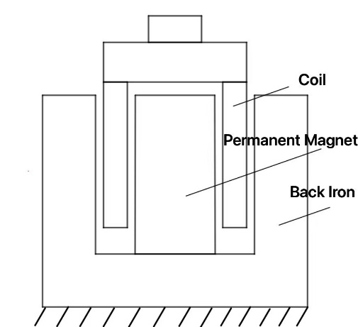
Figure 1: Structure of the Moving Coil Type Voice Coil Motor
2.1.2. Current Research Status
Qingsong Xu et al. [7] demonstrated the design, manufacturing, and testing process of a novel large-stroke XY precision positioning system. Finite element analysis showed that the theoretical working space of this system (as depicted in Figure 2) reaches 20 mm × 20 mm, with an area-to-worktable plane size ratio of 2.7778%. However, due to hardware limitations, the actual usable workspace is reduced to 11.75 mm × 11.66 mm, corresponding to an area ratio of just 0.9514%, which is nearly four times smaller than the smallest recorded in existing technology. The system also successfully eliminated buckling effects and supported an out-of-plane load capacity of over 20 kg. Experimental data revealed that the system's static cross-talk is less than 1.3%, and dynamic coupling is below -33 dB, indicating excellent decoupling between the two working axes. The dynamic characteristics of both axes are nearly identical, with resonance frequencies of 30 Hz. By applying a PID single-input single-output control strategy, the system achieved a resolution of 200 nm and positioning accuracy better than 340 nm. These results validate the efficiency of the micro-positioning system and demonstrate its potential for applications in precision positioning over a range from centimeters to sub-micrometers.
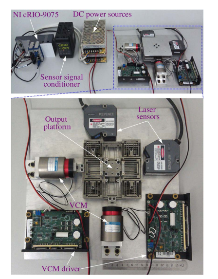
Figure 2: Real Image of the Drive System for the Moving Coil Type Voice Coil Motor [7]
Dapeng Fan et al. [8] introduced a novel monolithic spatial parallel XY stage (SPXYS), as shown in Figure 3, which has a centimeter-scale motion range and high load capacity, making it capable of withstanding substantial vertical loads and adapting to various operational conditions. The design of the SPXYS remains compact, enabling easy integration in limited spaces. The stage utilizes four matched voice coil motors (VCMs) as its driving mechanism, ensuring efficient and precise motion control. The electromechanical model of the SPXYS was established through matrix structural analysis (MSA) and imaging methods, providing a solid theoretical foundation for further optimization and control strategies. Additionally, the design process is clearly outlined, showcasing key technologies and innovative points from concept to realization. This study provides new methods and ideas for developing high-performance micro-manipulation platforms, particularly in the fields of micro-nano manufacturing and precision engineering.
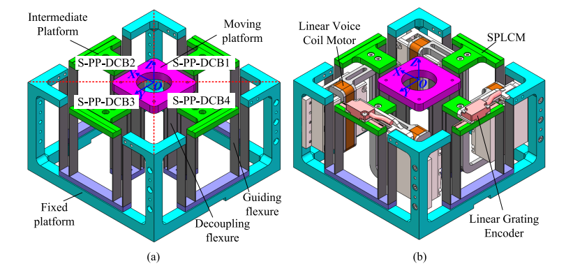
Figure 3: Structure of the Moving Coil Type Voice Coil Motor Driven Monolithic Spatial Parallel XY Stage[8]
2.2. Moving Magnet Type Voice Coil Motor
2.2.1. Principle of Moving Magnet Type Voice Coil Motor
The moving magnet type voice coil motor [6] is essentially a reversed version of the moving coil type, with the stator and mover interchanged. In this motor, as shown in Figure 4, the stator consists of an excitation coil and an iron core, while the mover is composed of alternating permanent magnets. The excitation coil is wound around the stator core, forming magnetic poles at the ends of the core. By altering the direction of the current in the coil, an alternating magnetic field is generated. The permanent magnets in the mover create a constant magnetic field, and the interaction between these two magnetic fields produces an axial alternating force that drives the motor shaft to move back and forth. This structure not only optimizes the magnetic field distribution but also enhances the motor’s motion efficiency.
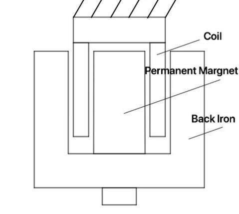
Figure 4: Structure of the Moving Magnet Type Voice Coil Motor
2.2.2. Current Research Status
Yangming Zhang et al. [9] designed and implemented a micro/nano XY servo platform based on flexure beams, as illustrated in Figure 5, aimed at achieving high-precision and large-stroke motion control. This platform adopts a novel compact flexure mechanism, combining Z-shaped and Π-shaped flexure components and a four-bar support structure to effectively minimize error motion and motion coupling. The prototype was manufactured using wire electrical discharge machining (WEDM) technology and 7075-T6 aluminum alloy. The servo system is equipped with two identical voice coil motors (VCA), each providing a stroke of 12.7 mm in one direction, driven by a high-bandwidth current amplifier. To achieve real-time control, two linear encoders with a resolution of 5 nanometers were used to provide displacement feedback, and a RENISHAW laser interferometer was integrated to offer independent displacement measurements with a measurement range of 1.5 mm × 1.5 mm. Due to the symmetrical structure, this XY flexure beam platform exhibits identical dynamic models in both X and Y directions, demonstrating its great potential for micro-nano manipulation and precision positioning applications.
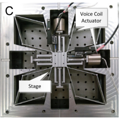
Figure 5: Schematic of the Moving Magnet Type Voice Coil Motor Driven Servo Platform [9]
Awtar et al.[10] proposed a system modeling and control method for a two-dimensional flexure beam servo system designed for micro-nano operations., As shown in Figure 6.They addressed major control challenges such as cross-axis coupling, dynamic uncertainties, and input saturation, which are more pronounced in flexible systems compared to traditional electromechanical systems. To tackle these issues, they developed an adaptive backstepping control method based on a disturbance observer, enabling high-precision servo control. This approach effectively manages model uncertainties and coupled dynamics while incorporating auxiliary systems to compensate for input saturation. The proposed control framework was successfully applied to a custom-designed nano-manipulation system, with real-time experimental results showing accuracy errors of less than 1% in various tasks like trajectory and contour tracking. Additionally, the comprehensive study on the novel flexure beam-based XY micro-nano positioning platform covered modeling, control law design, numerical simulations, and comparative experimental evaluations, ultimately achieving accuracy errors below 0.9% even in the presence of system uncertainties and disturbances.
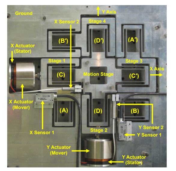
Figure 6: Real Image of the Moving Magnet Type Voice Coil Motor Driven Nano Positioning System [10]
3. Piezoelectric Actuators
3.1. Inchworm Type Piezoelectric Actuator
3.1.1. Motion Principle of the Inchworm Type Piezoelectric Actuator
The inchworm type piezoelectric actuator [3] mimics the crawling motion of an inchworm in nature by using a clamping mechanism for the head and tail, along with propulsion from the body (as shown in Figure 7). This actuator consists of two clamping units and one driving unit, each equipped with piezoelectric elements to generate motion. In its initial state, none of the piezoelectric elements are active, leaving a gap between the clamping units and the guide rail. When clamping unit 1 is powered on, it clamps onto the guide rail and remains fixed. The driving unit then powers up, causing the piezoelectric element to extend, pushing clamping unit 2 to the right. Subsequently, clamping unit 2 is activated to clamp the guide rail, while clamping unit 1 is powered off to release the rail. At the same time, the driving unit is powered off, causing clamping unit 1 to return to its original position due to the piezoelectric element’s contraction. Finally, clamping unit 1 is powered on again to clamp the rail, and clamping unit 2 is powered off, completing the cycle. Through repeated iterations of this process, the inchworm type piezoelectric actuator generates continuous stepwise motion, overcoming the limitations of traditional piezoelectric actuators such as short travel range and low precision. It finds wide applications in precision instruments and bioengineering.
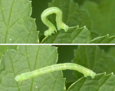

(a) Inchworm motion in nature (b) Motion principle
Figure 7: Schematic of the motion principle of the inchworm type piezoelectric actuator
3.1.2. Current Research Status
Peter E. Tenzer et al. [11] developed an innovative design tool (as shown in Figure 8) to support the development of positioners based on the piezoelectric effect. This tool provides a general framework for the geometry of each inchworm subsystem, facilitating the initiation of the design process and enabling subsequent optimization using finite element methods. The tool is based on the interaction characteristics between the piezoelectric actuators and their frame within the positioner. Experimental results validated the effectiveness of the design. The experimental evaluations of the designed positioner showed good consistency with the predicted performance characteristics from analysis and numerical simulations, although some discrepancies were attributed to simplified assumptions, such as infinite interface stiffness and rigid frame components. Additionally, geometric simplifications were made during the finite element analysis to reduce modeling time and manage the size of the model database, which contributed to the loss of precision. Despite these challenges, the developed inchworm positioner demonstrated key characteristics suitable for microfabrication. The estimated stiffness in the direction of motion was 88 m, the maximum thrust reached 150 Newtons, and a traversal speed of 8 mm/s was easily achievable, with a maximum of 20 mm/s. These performance indicators confirm the practical utility of the design tool in aiding the development of piezoelectric positioners.

Figure 8: Schematic of the inchworm type positioner [11]
3.2. Stick-Slip Type Piezoelectric Actuator
3.2.1. Motion Principle of the Stick-Slip Type Piezoelectric Actuator
The stick-slip type piezoelectric actuator [3] is a device that utilizes the piezoelectric effect to achieve precise positioning. Its working principle (as shown in Figure 9) is based on the deformation of piezoelectric materials under the influence of an electric field. When voltage is applied to the piezoelectric material, it stretches or contracts depending on the voltage, generating displacement. What makes the stick-slip type piezoelectric actuator unique is its combination of fine and coarse movement modes to achieve high-precision positioning. Specifically, the actuator consists of a piezoelectric element and a moving platform that adheres to the piezoelectric element. In the fine movement mode, the piezoelectric element undergoes small deformations, causing the platform to move slightly, which is ideal for extremely precise adjustments. In the coarse movement mode, the piezoelectric element undergoes rapid deformation, performing a cycle of "stick" (adhering at contact points) and "slip" (releasing at contact points), which allows the platform to move quickly over a larger range. This combination enables the stick-slip type actuator to achieve both rapid large-range positioning and fine micro-adjustments, making it highly suitable for applications that require high-precision positioning, such as micromachining and precision instrument calibration.
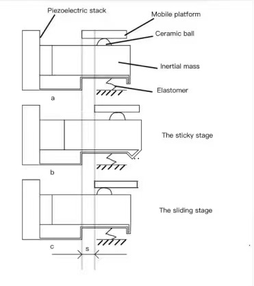
Figure 9: Schematic of the motion principle of the stick-slip type piezoelectric actuator
3.2.2. Current Research Status
Xiaohui Lu et al. [12] proposed an innovative linear stick-slip piezoelectric actuator (as shown in Figure 10), which cleverly combines an asymmetric flexure hinge with a triangular displacement amplification mechanism. This design enables high-speed operation even at lower frequencies. The actuator's design and working principles were thoroughly explained through theoretical analysis and simulation studies. To further investigate its performance, the research team developed a prototype and established a comprehensive experimental system. The experimental results demonstrated that the prototype achieved a stepping efficiency of up to 97.9% under optimal conditions. With a drive voltage of 100 VP-P and a frequency of 610 Hz, the actuator's maximum speed reached 20.17 mm/s, while its maximum load capacity was 2.4 N under a clamping force of 3.5 N. These characteristics show the potential and practical value of the actuator in the field of precision actuation.
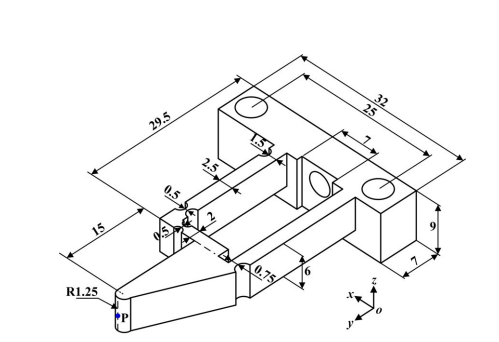
Figure 10: Parameter diagram of the stator of the linear stick-slip piezoelectric actuator [12]
Yangkun Zhang et al. [13] introduced a novel stick-slip piezoelectric actuator based on a triangular flexure driving mechanism (as shown in Figure 11). The actuator utilizes the stick-slip driving principle and achieves coupled motion through its innovative triangular driving mechanism, enabling strong clamping during the "stick" phase and efficient release during the "slip" phase, which significantly enhances the driving force. Furthermore, by increasing the design angle of the triangular structure, the clamping force and driving force can be greatly amplified. Finite element simulations validated the advantages of this driving mechanism in terms of driving force performance, and the study explored the effects of increasing the design angle on other aspects of actuator performance. The research showed that enlarging the design angle not only enhanced the clamping force but also increased the feed displacement, resulting in improvements in both driving force and speed. However, it should be noted that increasing the design angle leads to greater structural stress, which must be kept within acceptable limits. The prototype actuator, with a design angle of 60°, achieved a no-power self-locking force of up to 60 N and reached a positioning resolution of 40 nm at a driving frequency of 3500 Hz and 13 V drive voltage. At a driving voltage of 80 V, the actuator achieved a no-load speed of 46.67 mm/s and maintained a stable speed of 0.7 mm/s even under a 40 N load. Compared to existing technologies, the proposed actuator demonstrated approximately 11 times higher load-driving capability at lower input voltages and 3 times faster free-load driving speed, highlighting its clear advantages in terms of driving force and speed. Future work will involve applying this design to precision positioning mechanisms in 3D printing technology and further optimizing the structure to enhance performance.
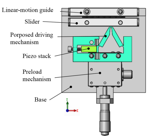
Figure 11: Structural diagram of the stick-slip piezoelectric actuator[13]
Mingxing Zhou et al. [14] proposed a linear piezoelectric actuator based on the stick-slip principle (as shown in Figure 12) and conducted comprehensive testing. The design utilizes a linear actuator with a variable vertical preload flexure hinge, enabling significant stick-slip motion while maintaining high-resolution stepping displacement capability. The core components of the actuator include a bridge-type flexure hinge mechanism, a compound parallelogram flexure hinge, and two piezoelectric stacks. The paper provides an in-depth description of the mechanical structure and motion principles of the linear actuator, supported by detailed performance evaluations through finite element analysis. Additionally, response surface methodology was used to optimize the flexure hinge parameters based on the finite element analysis to improve performance. To assess the actual performance of the actuator, the research team produced a prototype and conducted a series of experiments. The experimental results showed that the system achieved a maximum speed of 3.27 mm/s and a minimum stepping displacement precision of up to 0.29 µm. The team also performed vibration tests to determine the actuator's first natural frequency and observed its stick-slip performance under actual operating conditions. These experiments fully validated the feasibility of the actuator and demonstrated its significant advantages in motion speed and displacement precision compared to traditional stick-slip actuators.
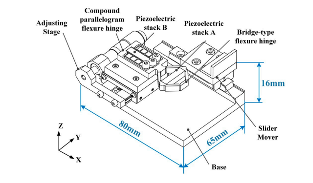
Figure 12: Schematic of the linear piezoelectric actuator based on the stick-slip principle[14]
3.3. Ultrasonic Piezoelectric Actuator
3.3.1. Motion Principle of Ultrasonic Piezoelectric Actuator
The ultrasonic piezoelectric actuator [3] can be categorized into standing wave type and traveling wave type based on the mode of ultrasonic wave propagation (as shown in Figure 13). The driving principle of the standing wave type piezoelectric actuator is illustrated by exciting two piezoelectric elements that are perpendicular to each other, causing them to vibrate at high frequency. This vibration moves the elastic body along an elliptical trajectory. The contact between the elastic body and the mover only occurs during the movement from point A to point B, while during the reverse motion, there is no contact with the mover, resulting in an intermittent driving mode. In contrast, the driving principle of the traveling wave ultrasonic piezoelectric actuator involves the coordinated movement of multiple piezoelectric elements. These elements cause each point on the surface of the stator to vibrate in an elliptical trajectory, thereby achieving continuous pushing of the mover. This design generates a smooth and consistent vibration output, making it suitable for applications requiring precise control and high-frequency motion, such as medical imaging and precision machining.
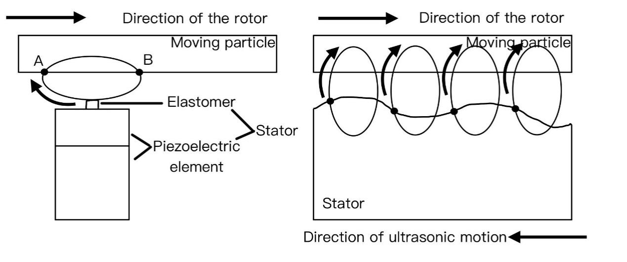
(a) Standing wave type (b) Traveling wave type
Figure 13: Schematic of the motion principle of ultrasonic piezoelectric actuators.
3.3.2. Current Research Status
Yuntian Guan et al. [15] analyzed the working principle of a piezoelectric ultrasonic actuator (as shown in Figure 14) and its applications under different excitation signals. They optimized the actuator structure through finite element simulation and verified its effectiveness. Subsequently, they designed and fabricated a cantilever beam piezoelectric ultrasonic actuator, applying it to a linear motion platform. The actuator's vibration characteristics were thoroughly tested, and impedance matching was completed. The study found that a zirconia-silicon nitride friction pair was most suitable for the actuator. The developed linear motion platform, when excited by specific sinusoidal alternating current signals, achieved a speed of 426.2 mm/s and could handle a load of over 23 kg. Under pulse signal excitation, it exhibited a high displacement resolution of 85 nm. Finally, the custom-designed power supply and control system demonstrated stability, excellent speed tracking ability, and low speed fluctuation under both low-speed and sinusoidal speed tracking conditions.
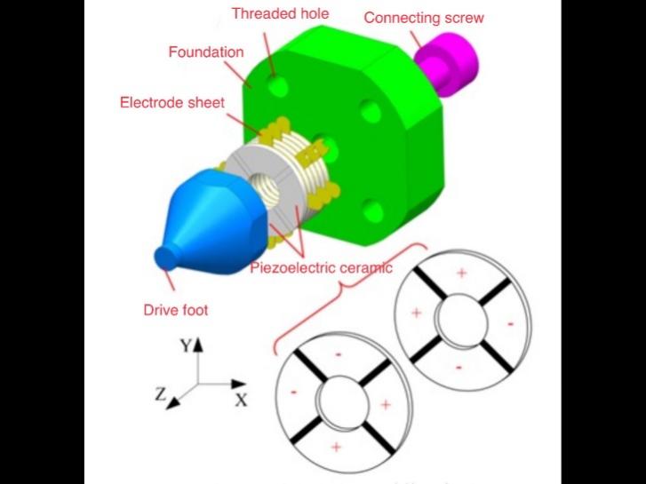
Figure 14: Schematic of the ultrasonic piezoelectric actuator[15]
Qiu et al.[16] demonstrated through analysis and experiments that the performance of a hybrid transducer ultrasonic motor (HTUSM) (as shown in Figure 15), including transducer efficiency, can be significantly improved under high static preload when using the appropriate lubricant. First, simulations were conducted using an equivalent circuit under both dry and lubricated conditions, and the results indicated that under high static preload with lubrication, HTUSM characteristics were more ideal than under dry conditions. Then, experimental studies on the mechanical performance of HTUSM verified that lubrication under high preload improves motor performance, which was in good agreement with the simulation results. The maximum electromechanical transduction efficiency of HTUSM increased significantly from 28% under dry conditions to 68% under lubricated conditions.
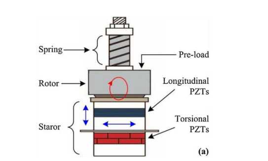
Figure 15: Schematic of the hybrid transducer ultrasonic motor (HTUSM)[16]
4. Comparison and Outlook
Based on the analysis of domestic and international research status, it is evident that research in the field of flexure motion has matured. With the continuous advancement of technology, there will be increasing focus on the study of large-stroke platforms. As compliant mechanism technology progresses, platforms are expected to evolve toward larger strokes, multiple degrees of freedom, higher resolution, and reduced coupling errors.
(1) Moving Coil Type Voice Coil Motor is favored for its simple structure and fast response, making it especially suitable for applications with low power requirements and fast operations. However, this type of motor faces challenges such as wire fly-offs and inadequate heat dissipation, which limit its use in high-power applications and may affect long-term reliability.
(2) Moving Magnet Type Voice Coil Motor, due to its compact structure and high power density, is widely used in high-performance applications. The use of a permanent magnet array allows for frictionless operation, enhancing operational efficiency and equipment lifespan. However, this type of motor is more complex in design and manufacturing, with higher demands on the quality and strength of the permanent magnets, which can increase costs. Special attention is also required for magnetic field coupling and nonlinear thrust, posing technical challenges.
(3) Inchworm Type Piezoelectric Actuator achieves large stroke output by mimicking the motion of an inchworm. Its advantages include a simple structure, ease of manufacture, and the ability to produce large displacements. However, its downside lies in its relatively slow speed and lower precision due to the limitations of its motion mechanism, making it suitable for applications where high speed is not a requirement.
(4) Stick-Slip Piezoelectric Actuator uses the stick-slip effect to achieve high precision and stable motion. Its main advantages are its ability to generate large output forces and high positioning accuracy, making it ideal for micro-nano positioning applications. However, its disadvantages include the complexity of its control strategy and its sensitivity to environmental conditions (e.g., temperature and humidity), which can affect its stability and reliability.
(5) Ultrasonic Piezoelectric Actuator achieves small displacements at high frequencies through ultrasonic vibration. Its advantages include fast response and high resolution, making it suitable for precision positioning and micro-operation. However, its limitations include a relatively small stroke and reduced performance under high load conditions, which restrict its widespread use in large-stroke applications.
5. Conclusion
This paper reviews the current research status of flexure motion platforms driven by voice coil motors and piezoelectric actuators, focusing on two types of voice coil motors (moving coil type and moving magnet type) and three types of piezoelectric actuators (inchworm type, ultrasonic type, and stick-slip type). With the development of compliant mechanism technology, platforms will progress toward larger strokes, multiple degrees of freedom, higher resolution, and lower coupling errors. The motion principles of the two types of voice coil motors and three types of piezoelectric actuators were explained, and a comparison was made between domestic and international research. Compared to international products, domestic products offer better cost-effectiveness.
The paper also discusses future research directions, including moving coil type voice coil motors need to address the issues of wire fly-offs and insufficient heat dissipation, moving magnet type voice coil motors must focus on reducing the cost of permanent magnets and solving the problems of magnetic field coupling and nonlinear thrust, inchworm type piezoelectric actuators should work on improving precision while maintaining their simple structure, stick-slip piezoelectric actuators need to enhance stability and reliability to adapt to complex control strategies and environmental conditions, ultrasonic piezoelectric actuators must focus on improving performance in high-load environments for large-stroke applications.
References
[1]. Li, T. (2003). Structural topology characteristics and degree of freedom analysis of flexible mechanisms. Mechanical Science and Technology, 01, 107-109.
[2]. Zhang, D., & Feng, X. (2006). Technical principles of voice coil motors. Journal of North University of China (Natural Science Edition), 03, 224-228.
[3]. Zhang, T., Ma, R., Wang, Y., & others. (2023). Review of stepping piezoelectric actuators with large travel. Journal of Chongqing University of Technology (Natural Science Edition), 37(09), 280-294.
[4]. Zhou, J. (2015). Intelligent manufacturing: The main direction of "Made in China 2025". China Mechanical Engineering, 26(17), 2273-2284.
[5]. Feng, S. (2014). Current status and trends of wearable devices. Information and Communication Technology, 8(03), 52-57.
[6]. Chai, J., & Gui, X. (2021). A review of structure optimization and applications of voice coil motors. Transactions of China Electrotechnical Society, 36(06), 1113-1125.DOI:10.19595/j.cnki.1000-6753.tces.200725.
[7]. Xu, Q. (2013). Design and development of a compact flexure-based XY precision positioning system with centimeter range. IEEE Transactions on Industrial Electronics, 61(2), 893-903.DOI:10.1109/TIE.2013.2257139.
[8]. Fan, S., Liu, H., & Fan, D. (2018). Design and development of a novel monolithic compliant XY stage with centimeter travel range and high payload capacity. Mechanical Sciences, 9(1), 161-176.DOI:10.5194/ms-9-161-2018.
[9]. Zhang, Y., Yan, P., & Zhang, Z. (2016). A disturbance observer-based adaptive control approach for flexure beam nano manipulators. ISA Transactions, 206-217.DOI:10.1016/j.isatra.2015.10.005.
[10]. Awtar, S., & Parmar, G. (2010). Design of a large range XY nanopositioning system. Journal of Mechanisms and Robotics, 1(2).DOI:10.1115/1.4023874.
[11]. Tenzer, P. E., & Mrad, R. B. (2004). A systematic procedure for the design of piezoelectric inchworm precision positioners. IEEE/ASME Transactions on Mechatronics, 9(2), 427-435.DOI:10.1109/TMECH.2004.828627.
[12]. Lu, X., Gao, Q., Li, Y., & others. (2020). A linear piezoelectric stick-slip actuator via triangular displacement amplification mechanism. IEEE Access, 8, 6515-6522.DOI:10.1109/ACCESS.2019.2963680.
[13]. Zhang, Y., Yuxin, & others. (2018). A novel stick-slip piezoelectric actuator based on a triangular compliant driving mechanism. IEEE Transactions on Industrial Electronics.DOI:10.1109/TIE.2018.2868274.
[14]. Zhou, M., Fan, Z., Ma, Z., & others. (2017). Design and experimental research of a novel stick-slip type piezoelectric actuator. Micromachines, 8(5).DOI:10.3390/mi8050150.
[15]. Wang, L., Guan, Y., Liu, Y., & others. (2020). A compact cantilever-type ultrasonic motor with nanometer resolution: Design and performance evaluation. IEEE Transactions on Industrial Electronics, PP(99), 1-1.DOI:10.1109/TIE.2020.2965481.
[16]. Qiu, W., Mizuno, Y., Koyama, D., & others. (2013). Efficiency improvement of hybrid transducer-type ultrasonic motor using lubricant. IEEE Transactions on Ultrasonics, Ferroelectrics, and Frequency Control, 60(4), 786-794.DOI:10.1109/TUFFC.2013.2627.
Cite this article
Zhu,H. (2025). A Review of Flexure Motion in Piezoelectric Actuators and Voice Coil Actuators. Applied and Computational Engineering,123,134-146.
Data availability
The datasets used and/or analyzed during the current study will be available from the authors upon reasonable request.
Disclaimer/Publisher's Note
The statements, opinions and data contained in all publications are solely those of the individual author(s) and contributor(s) and not of EWA Publishing and/or the editor(s). EWA Publishing and/or the editor(s) disclaim responsibility for any injury to people or property resulting from any ideas, methods, instructions or products referred to in the content.
About volume
Volume title: Proceedings of the 5th International Conference on Materials Chemistry and Environmental Engineering
© 2024 by the author(s). Licensee EWA Publishing, Oxford, UK. This article is an open access article distributed under the terms and
conditions of the Creative Commons Attribution (CC BY) license. Authors who
publish this series agree to the following terms:
1. Authors retain copyright and grant the series right of first publication with the work simultaneously licensed under a Creative Commons
Attribution License that allows others to share the work with an acknowledgment of the work's authorship and initial publication in this
series.
2. Authors are able to enter into separate, additional contractual arrangements for the non-exclusive distribution of the series's published
version of the work (e.g., post it to an institutional repository or publish it in a book), with an acknowledgment of its initial
publication in this series.
3. Authors are permitted and encouraged to post their work online (e.g., in institutional repositories or on their website) prior to and
during the submission process, as it can lead to productive exchanges, as well as earlier and greater citation of published work (See
Open access policy for details).
References
[1]. Li, T. (2003). Structural topology characteristics and degree of freedom analysis of flexible mechanisms. Mechanical Science and Technology, 01, 107-109.
[2]. Zhang, D., & Feng, X. (2006). Technical principles of voice coil motors. Journal of North University of China (Natural Science Edition), 03, 224-228.
[3]. Zhang, T., Ma, R., Wang, Y., & others. (2023). Review of stepping piezoelectric actuators with large travel. Journal of Chongqing University of Technology (Natural Science Edition), 37(09), 280-294.
[4]. Zhou, J. (2015). Intelligent manufacturing: The main direction of "Made in China 2025". China Mechanical Engineering, 26(17), 2273-2284.
[5]. Feng, S. (2014). Current status and trends of wearable devices. Information and Communication Technology, 8(03), 52-57.
[6]. Chai, J., & Gui, X. (2021). A review of structure optimization and applications of voice coil motors. Transactions of China Electrotechnical Society, 36(06), 1113-1125.DOI:10.19595/j.cnki.1000-6753.tces.200725.
[7]. Xu, Q. (2013). Design and development of a compact flexure-based XY precision positioning system with centimeter range. IEEE Transactions on Industrial Electronics, 61(2), 893-903.DOI:10.1109/TIE.2013.2257139.
[8]. Fan, S., Liu, H., & Fan, D. (2018). Design and development of a novel monolithic compliant XY stage with centimeter travel range and high payload capacity. Mechanical Sciences, 9(1), 161-176.DOI:10.5194/ms-9-161-2018.
[9]. Zhang, Y., Yan, P., & Zhang, Z. (2016). A disturbance observer-based adaptive control approach for flexure beam nano manipulators. ISA Transactions, 206-217.DOI:10.1016/j.isatra.2015.10.005.
[10]. Awtar, S., & Parmar, G. (2010). Design of a large range XY nanopositioning system. Journal of Mechanisms and Robotics, 1(2).DOI:10.1115/1.4023874.
[11]. Tenzer, P. E., & Mrad, R. B. (2004). A systematic procedure for the design of piezoelectric inchworm precision positioners. IEEE/ASME Transactions on Mechatronics, 9(2), 427-435.DOI:10.1109/TMECH.2004.828627.
[12]. Lu, X., Gao, Q., Li, Y., & others. (2020). A linear piezoelectric stick-slip actuator via triangular displacement amplification mechanism. IEEE Access, 8, 6515-6522.DOI:10.1109/ACCESS.2019.2963680.
[13]. Zhang, Y., Yuxin, & others. (2018). A novel stick-slip piezoelectric actuator based on a triangular compliant driving mechanism. IEEE Transactions on Industrial Electronics.DOI:10.1109/TIE.2018.2868274.
[14]. Zhou, M., Fan, Z., Ma, Z., & others. (2017). Design and experimental research of a novel stick-slip type piezoelectric actuator. Micromachines, 8(5).DOI:10.3390/mi8050150.
[15]. Wang, L., Guan, Y., Liu, Y., & others. (2020). A compact cantilever-type ultrasonic motor with nanometer resolution: Design and performance evaluation. IEEE Transactions on Industrial Electronics, PP(99), 1-1.DOI:10.1109/TIE.2020.2965481.
[16]. Qiu, W., Mizuno, Y., Koyama, D., & others. (2013). Efficiency improvement of hybrid transducer-type ultrasonic motor using lubricant. IEEE Transactions on Ultrasonics, Ferroelectrics, and Frequency Control, 60(4), 786-794.DOI:10.1109/TUFFC.2013.2627.