


1. Introduction
In recent years, China's socio-economic development by leaps and bounds, the large and medium-sized cities continue to improve the construction of transportation, the size of the city is also expanding. With the progress of China's urbanization, a large number of rural populations into the city, most of the rural population gradually turned into urban population, people's standard of living is also increasingly improved, the consumption of water at the same time is also on the rise, which has led to the purchase of private cars straight line up, almost reached the situation of a family of a car or even a family of multiple cars. According to the statistics of the available information, the national motor vehicle ownership has reached 440 million, including 345 million cars and 24.72 million new energy vehicles, and the number of people learning to drive a license is also a growing trend, compared with the first half of the year increased by 17.36%, and it is expected that the number of motor vehicles will continue to grow in the future [1]. At the same time, traffic congestion and traffic safety hazards have become an inevitable problem. In the face of such traffic problems, the design of intelligent traffic light system can effectively reduce the burden on society.
When the use of intelligent traffic signals can improve the management level of urban roads, do to reduce the rate of vehicle delays and reduce the incidence of traffic accidents, reducing the government's manpower and financial consumption, and at the same time to strengthen the control of the traffic flow through the controllable [2]. At the same time, it can strengthen the control of traffic flow and respond to emergencies by controllable buttons, such as ambulances for first aid patients and fire trucks to fire scenes, etc., which can greatly improve the efficiency of traffic signals and enhance the priority of traffic in the face of emergencies, so as to make the whole intersection more orderly, improve the efficiency of traffic flow, reduce traffic congestion and reduce the waste of resources.
The design of this paper is to complete a digital circuit based on the traffic signal light circuit design and its simulation of the effect of the presentation, as well as in the traffic area similar to the intersection, with the help of big data system, to do a controlled change in the color of the signal light to try to solve most of the emergencies, to achieve the control of the traffic flow and reduce the occurrence of traffic accidents.
2. Analysis of the theoretical basis of signaling logic at traffic intersections
2.1. The basic logic of traffic lights
First of all, the circuit system designed in this paper for red-green conversion of signals, in which the main manifestation is a four-way intersection in the north-south (NS) and east-west (EW) directions, and the time of pedestrian crossing the intersection is also counted, and the dwell time of each signal in a specific state is managed by using a timer, in which the dwell time of the green and red signals is 30 seconds, and the dwell time of the yellow signals is 5 seconds. The logic of the circuit sets the first state Q0 in the east-west direction to be green, like 000, and the next state Q1 in the north-south direction to be yellow, i.e., 001, and we have shortened the truth table of the logic part by combining the green and the yellow color into the same state, which reduces the chances of error in the design and simulation of the circuit. Therefore, there are only two states, 0 and 1, i.e. 1 for the green and yellow signaling process and 0 for the red signaling process, and then the east-west process and the north-south process can be considered as equivalent based on the fact that their timing is the same for the signaling changes in both directions. The logic truth table of the circuit is shown in table 1.
Table 1: The logic truth table
Q0 | Timer | NSG | NSY | NER | EWG | EWY | EWR | PeD | Q1 |
000 | 1(30s) | 1 | 0 | 0 | 0 | 0 | 1 | 0 | 001 |
001 | 1(5s) | 0 | 1 | 0 | 0 | 0 | 1 | 0 | 010 |
010 | 1(30s) | 0 | 0 | 1 | 1 | 0 | 0 | 0 | 011 |
011 | 1(5s) | 0 | 0 | 1 | 0 | 1 | 0 | 0 | 000 |
100 | 0 | 0 | 0 | 1 | 0 | 0 | 1 | 1 | 101 |
101 | 1(30s) | 0 | 0 | 1 | 0 | 0 | 1 | 1 | 000 |
2.2. Additional Logic
The additional logic designed in this paper based on the basic signal light circuit is firstly to optimize the response of the traffic light to the pedestrian crossing button, after people press the crossing button, the traffic light will judge the current traffic road condition at the intersection according to the big data, and calculate the faster time to show the green light for pedestrians to pass as well as the red light for the vehicles on the other direction, to make sure that the pedestrians cross the street in a more secure way, and meanwhile, when the people have finished crossing the street, and then At the same time, when people have finished crossing the street, then through big data analysis, it shows the green light for the vehicles, minimizing the delay caused by the inefficiency of signal timing for the vehicles.
The second aim is to give priority to emergency vehicles, when an emergency vehicle is detected, so that the traffic signals can be switched quickly in case of emergency, the system will immediately switch all traffic signals to the yellow delay state before switching to the state of priority for emergency vehicles to provide a smooth passage, after which the system returns to the previous traffic state. If the current state already supports emergency vehicle traffic, the state is extended for an additional delay period. The system is designed to effectively prioritize emergency vehicle traffic while minimizing disruption to normal traffic.
3. Introduction to Components
3.1. 555 Timer
555 timer by Signetics company introduced a proposed and digital functions combined with the integrated device, which has the advantages of low price, ease of use and reliability and is widely cited in the field of electronic circuits. 555 timer has a total of eight pins, the input pins can be combined with the circuit, constituting the Schmitt trigger, mono-stable trigger and multi-harmonic oscillator and so on. 555 timer inputs have a total of 0 and 1 states, respectively, indicating low and high levels, which can operate in three modes - monostable mode, bistable mode and unsteady mode timer inputs have a total of two states, 0 and 1, which indicate low and high levels, respectively, and it can operate in three modes - monostable mode, bistable mode, and unsteady mode [3].
This paper needs a polyharmonic oscillator consisting of a 555 timer, which does not have an input signal, but only an output signal, which is generated by the circuit's internal self-generation of the input voltage, similar to the waveform generator in analog circuits. The polyharmonic oscillator consisting of 555 timer can output two types of waveforms, triangular and rectangular waveforms [4].
The principle of operation of the polyharmonic oscillator is to use the charging and discharging of capacitors to constitute, when the capacitor is charging, the voltage at the ends of the capacitor C gradually increases and the output is high level, when the capacitor is discharging, the voltage at the ends of the capacitor gradually decreases and the output is low level. The period of a polyharmonic oscillator is the duration of the high level plus the duration of the low level, i.e. T=T1+T2=0.7*(R1+2R2)C. The 555-timer module is shown in Figure 1.
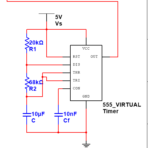
Figure 1: The 555-timer module
3.2. Integrated display decoder 74LS48
Integrated display decoder 74LS48D has a total of 14 pins, the input side of a total of 4 pins, respectively, 4 binary code, the output side of the 7 pins, the output signal to control the digital tube to output different numbers. In order to prevent the digital tube will burn out, to be in the integrated display decoder 74LS48D and the digital tube between the circuit in series with a resistor, play a role in limiting current. In addition to the input and output of the 11 pins, the remaining three pins LT, RBI, BI \ RBO, respectively, for the visual light input pins, dynamic facing input signal pins, extinguish the light input signal \ dynamic facing output signal pins.
Visual light input pin (LT), when it is in the low-level state, the seven output ports output are 1, and then drive the connection of the common cathode digital tube display 8 glyphs, mainly for checking whether each diode in the digital tube can operate normally; dynamic face input signal pin (RBI) can be on the input side of the “0” does not display, such as “80.50” at the end of the “0” does not display, eliminating redundancy. Display, such as “80.50” at the end of the “0” is not displayed, eliminating the redundant part. When RBI is at a low level, the “0” in the digital tube will be hidden, and when it is at a high level, the output “0” signal will be displayed; Lights Out Input Signal /Dynamic Facing Output Signal Pin (BI/RBO) can be used as both an input signal and an output signal pin. The BI\RBO pin can be used as either an input signal or an output signal. When BI/RBO is the input signal, for the BI state, when the pin is controlled by a low level, the priority of the other pins in the highest, so that the outputs are 0, that is, the digital tube lights out. When the pin is given to the suspension of this pin is not processed, the other pins control signals play a role in controlling. The integrated display decoder is shown in Figure 2.
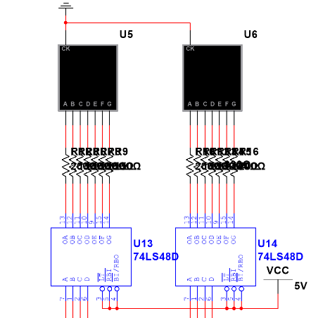
Figure 2: the integrated display decoder
3.3. Decimal addition and subtraction counter 74LS192
In 74LS192 counter, A, B, C, D terminals are the input terminals of preset number, PL non-terminal controls whether the number is preset or not, and connects to high level under normal counting condition, MR is the clearing terminal, and needs to be connected to low level if it does not need to be cleared, UP and DOWN terminals are connected to the addition counting pulses and the subtraction counting pulses, which can realize the addition or subtraction arithmetic operation by giving different counting pulses, QA, QB, QC, QD terminals constitute the four-bit binary number output, QD is the highest bit, QA is the lowest bit, BO and CO ports are the borrowing output port and progressive output port. QB, QC and QD terminals form a four-bit binary number output, with QD as the highest bit and QA as the lowest bit.The BO and CO ports are the borrowed output ports and the incoming output ports can be directly cascaded and expanded with the help of the incoming and borrowed output terminals without the need for external circuits [5]. CLR is an asynchronous reset function and its priority is also the highest. The decimal addition and subtraction counter module is shown in Figure 3.
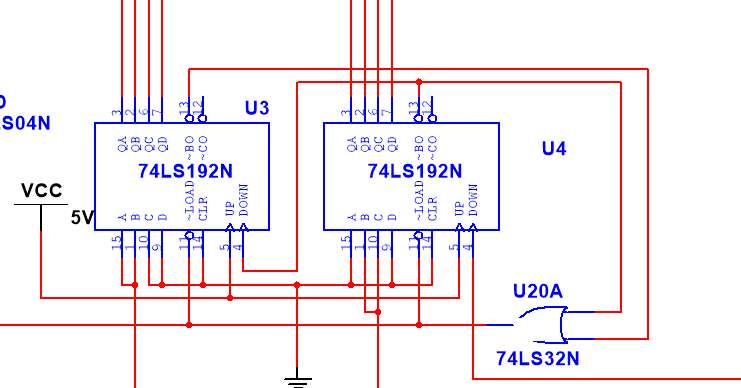
Figure 3: the decimal addition and subtraction counter module
3.4. Synchronous addition counter and 3-wire - 8-wire decoder
Synchronous addition counter 74LS161 as a counter has high performance and low energy consumption with very small delay to enhance the efficiency of the circuit [6]. In 74LS161, A, B, C, D are the 4 data input ports, QA, QB, QC, QD are the outputs, CLK is the clock signal which is loaded by the periodic pulse signal. CLR port is the highest priority port, when in CLR port is at low level, CR is the reset terminal or clearing terminal, all 4 output ports are 0, when CR is 1, it is a suspended state, which is controlled by the preset When CR is 1, it is suspended and controlled by preset (LOAD). When LOAD is low, the signals from the control input ports are transported to the outputs. When LOAD and CLR are both 1, the two enable signals ENP and ENT are 0 to control the whole counter, and the counter state remains unchanged; when all four port signals are 1, the counter performs addition calculation according to 4-bit binary code [7].
3-wire - 8-wire decoder 74LS138 a total of 16 pins, pin 8 ground, pin 16 connected to the power supply, the remaining 14 pins in the ABC pin for the binary input port, C for the high, A for the low Y0 ~ 7 for the output port, are active low level. G1, G2A, G2B for the enable signal must be in the active level decoder 74LS138 in order to decode properly! G1, G2A, G2B are enable signals which must be at valid level for the decoder 74LS138 to work properly. The synchronous addition counter and 3-wire-8-wire decoder modules are shown in Figure 4.
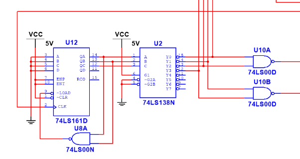
Figure 4: The synchronous addition counter and 3-wire-8-wire decoder modules
4. Traffic light signal circuit design
4.1. Introduction to Multisim
This paper uses NI Multisim, a powerful software for circuit design and simulation, which is widely used in education, scientific research, engineering design, etc. NI Multisim has an extremely rich component library, and its simulation function makes our circuit design run and show out very well. At the same time, Multisim also provides researchers with a lot of help, you can use the software for signal, waveform and other circuit analysis, for the results of scientific research to provide a great help, and for those integrated circuits, software engineers to provide a platform for trial and error, and help the product design of electronic circuits [8].
4.2. System counting control
In this circuit, two add and subtract counters 74LS192 are first used for countdown purpose. When the down function of the integrated display decoder outputs a pulse, the up function is at a high level, at which time the counters can realize the subtraction function.
4.3. Multi-Harmonic Oscillation Circuit Control
The add and subtract counter 74LS192 subtraction function counts down the second pulses generated by the multi-resonance oscillator circuit consisting of 555 timers. When the whole circuit starts powering up, the two outputs of the add/subtract counter 74LS192 are 00, which is 4 zeros in binary, and when its word count port is low, the QA~QD outputs of the add/subtract counter 74LS192 are equal to the inputs of the ABCD preset numbers, i.e., the outputs are equal to the inputs when the load terminal is low, so that the outputs are controlled to count down the time by controlling the input word count port.
4.4. Design and display of countdown timers
In the design of the entire traffic signal, set into two directions with four traffic lights, speaking green and yellow lights as a whole, the time of the red light as the sum of the time of the green and yellow lights. Therefore, the judgment is only to determine the green light-yellow light main and secondary roads have yellow and green lights, a total of four states. The pulse side of the counter is accessed by using the alphanumeric port of a quadratic addition counter, 74LS161, with a 3-wire - 8-wire decoder, 74LS138. There are a total of four states - east and west yellow and green lights, and north and south yellow and green lights, and these four states are counted from 0. When the 3-wire - 8-wire decoder 74LS138 input is all 0, the other are high, when the input is 1, Y1 is 0, and so on, to 4 0 as a flag bit, to control the input of the addition and subtraction counter 74LS192.
5. Simulation effect of the whole circuit
5.1. Simulation results of the designed circuit
The six-unit circuits of the intersection traffic signal controller: 555 timer module, integrated display decoder module, decimal addition and subtraction counter module, synchronous addition counter module, 3-wire-8-wire decoder module and traffic signal display circuit are connected together. Click on the Run button in Multisim for traffic light control circuit simulation demonstration. First of all, the green light is on at the intersection of the main road (southeast direction), and the red light is on at the intersection of the secondary road (north-south direction), and the vehicles on the main road can pass freely; the vehicles on the secondary road are prohibited to pass. Two digital tube display time from the preset 30 s, to every second minus 1, reduced to 0, the main intersection green light converted to yellow, preset time of 5s, to every second minus 1, reduced to the number of 0, the main intersection yellow light is converted to red, the main road vehicles are prohibited to pass, the secondary intersection of the red light is converted to green, the secondary roads on the vehicle can be free to pass. The time display of the green light at the secondary road junction is reduced from the preset 30 s to 1 per second, and when it is reduced to 0, the green light at the secondary road junction is converted to yellow, and the time display is reduced from the preset 5s to 1 per second, and when it is reduced to the count of 0, the green light at the main intersection is on, and the red light at the secondary road junction is on, and the cycle is repeated in this order [9]. The overall simulation circuit of the intersection traffic signal controller is shown in Figure 5.
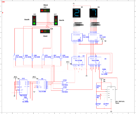
Figure 5: The overall simulation circuit of the intersection traffic signal controller
5.2. Emergency Circuit Design
In the design of the basic signal light circuit, you can add infrared sensors or big data detector, real-time detection of traffic flow, so that it can automatically adjust the countdown time. Through the calculation of big data, from the end of a green signal on the main and secondary roads, detecting the number of vehicles waiting for the red light, to obtain its real-time data, through the calculation of time to do the shortest possible time, to be able to let the most vehicles pass through the intersection, to reduce the delay rate of the road vehicles, and to alleviate the traffic congestion in the city [10]. In addition, there is an infrared remote control device, set up emergency vehicles bound special infrared signals, when the detection of ambulances, fire trucks and other emergency vehicles appear, designed for the other direction of the road, if it is waiting for the red light in the case of depending on the situation to increase the time of 20 seconds, the emergency vehicle direction of the green light passes to increase the time of 10 seconds; if it is the other direction of the road for the passage of the green light, then the signal light will be changed to a yellow light, prompting the If the other direction of the road is green, the signal light will be changed to yellow, prompting vehicles to slow down, 5 seconds after the change to red, to give priority to the emergency vehicles to pass.
6. Conclusion
In this paper, on the basis of the basic digital circuits, the big data detection and emergency button are added, so that when there are complex road conditions, real-time calculations can be made on the road conditions, which greatly improves the efficiency of the intersection, reduces the degree of congestion on the road, and in this environment of accelerated urbanization, it allows the private cars and public transportation to get a better operation, and at the same time, improves the safety of the road. It also improves the safety of roads and provides a reasonable solution for the convenience of traffic management. With the development of time and science and technology, the traffic signal control system is constantly optimized and innovated, combining technology and traditional signals to create a better urban network construction.
References
[1]. China Environmental Monitor. The national motor vehicle up to 440 million in the first half of this year, the new registration of new energy vehicles, 4, 397, 000, 2024, (01). https://www.gov.cn/lianbo/bumen/202408/content_6967617.htm
[2]. Hongmei W, Yigang R, Xingyu L, et al. Intelligent Transportation System in Urban Traffic Management and Challenges. Time Auto, 2024, (04).
[3]. Abrar M M. Design and implementation of astable multivibrator using 555 timer. IOSR J. Electr. Electron. Eng, 2017, 12(1): 22-29.
[4]. Bo D. Application of 555 timer in digital electronics. Electronics, 2023, (04).
[5]. Bryant M D, Yan S, Tsang R, et al. A mixed signal (analog-digital) integrator design. IEEE Transactions on Circuits and Systems I: Regular Papers, 2012, 59(7): 1409-1417.
[6]. Yue H, Mu H, Liu H, et al. Experiment design: Intelligent traffic management system. 2020 15th IEEE Conference on Industrial Electronics and Applications (ICIEA). IEEE, 2020: 1744-1749.
[7]. Long Z. N-system counter design based on 74LS16X. Ninth International Symposium on Sensors, Mechatronics, and Automation System (ISSMAS 2023). SPIE, 2024, 12981: 73-77.
[8]. David H. Application and Exploration of NI Multisim Software in Virtual Simulation Teaching of Digital Circuits. Communication World, 2024, (02).
[9]. Xiaoyan C, Xiaoliang L, Rong Y, et al. Design and Simulation of Multisim-based Traffic Signal Light Controller. Journal of Yellow River Institute of Science and Technology, 2023, (10).
[10]. Shenbagavalli S, Priyadharshini T, Sowntharya S, et al. Design and implementation of smart traffic controlling system. International Journal of Engineering Technology Research & Management, 2020, 4(4): 28-36.
Cite this article
Li,Z. (2025). Design and Simulation of Traffic Light Signal Circuit Based on Digital Circuits. Applied and Computational Engineering,126,194-201.
Data availability
The datasets used and/or analyzed during the current study will be available from the authors upon reasonable request.
Disclaimer/Publisher's Note
The statements, opinions and data contained in all publications are solely those of the individual author(s) and contributor(s) and not of EWA Publishing and/or the editor(s). EWA Publishing and/or the editor(s) disclaim responsibility for any injury to people or property resulting from any ideas, methods, instructions or products referred to in the content.
About volume
Volume title: Proceedings of the 5th International Conference on Materials Chemistry and Environmental Engineering
© 2024 by the author(s). Licensee EWA Publishing, Oxford, UK. This article is an open access article distributed under the terms and
conditions of the Creative Commons Attribution (CC BY) license. Authors who
publish this series agree to the following terms:
1. Authors retain copyright and grant the series right of first publication with the work simultaneously licensed under a Creative Commons
Attribution License that allows others to share the work with an acknowledgment of the work's authorship and initial publication in this
series.
2. Authors are able to enter into separate, additional contractual arrangements for the non-exclusive distribution of the series's published
version of the work (e.g., post it to an institutional repository or publish it in a book), with an acknowledgment of its initial
publication in this series.
3. Authors are permitted and encouraged to post their work online (e.g., in institutional repositories or on their website) prior to and
during the submission process, as it can lead to productive exchanges, as well as earlier and greater citation of published work (See
Open access policy for details).
References
[1]. China Environmental Monitor. The national motor vehicle up to 440 million in the first half of this year, the new registration of new energy vehicles, 4, 397, 000, 2024, (01). https://www.gov.cn/lianbo/bumen/202408/content_6967617.htm
[2]. Hongmei W, Yigang R, Xingyu L, et al. Intelligent Transportation System in Urban Traffic Management and Challenges. Time Auto, 2024, (04).
[3]. Abrar M M. Design and implementation of astable multivibrator using 555 timer. IOSR J. Electr. Electron. Eng, 2017, 12(1): 22-29.
[4]. Bo D. Application of 555 timer in digital electronics. Electronics, 2023, (04).
[5]. Bryant M D, Yan S, Tsang R, et al. A mixed signal (analog-digital) integrator design. IEEE Transactions on Circuits and Systems I: Regular Papers, 2012, 59(7): 1409-1417.
[6]. Yue H, Mu H, Liu H, et al. Experiment design: Intelligent traffic management system. 2020 15th IEEE Conference on Industrial Electronics and Applications (ICIEA). IEEE, 2020: 1744-1749.
[7]. Long Z. N-system counter design based on 74LS16X. Ninth International Symposium on Sensors, Mechatronics, and Automation System (ISSMAS 2023). SPIE, 2024, 12981: 73-77.
[8]. David H. Application and Exploration of NI Multisim Software in Virtual Simulation Teaching of Digital Circuits. Communication World, 2024, (02).
[9]. Xiaoyan C, Xiaoliang L, Rong Y, et al. Design and Simulation of Multisim-based Traffic Signal Light Controller. Journal of Yellow River Institute of Science and Technology, 2023, (10).
[10]. Shenbagavalli S, Priyadharshini T, Sowntharya S, et al. Design and implementation of smart traffic controlling system. International Journal of Engineering Technology Research & Management, 2020, 4(4): 28-36.