


1. Introduction
With the intensifying global trend of population aging and changing lifestyles, the number of patients with lower limb movement dysfunction caused by factors such as stroke, spinal cord injury, and traumatic brain injury is rising annually. According to the World Health Organization, there are approximately 15 million stroke cases worldwide each year, with about one-third of these patients experiencing long-term movement disabilities[1]. These diseases not only severely impact the daily lives of patients but also impose a heavy burden on families and society. In traditional rehabilitation therapy, training typically relies on manual operations by rehabilitation therapists, which is inefficient and requires substantial human resources, making it difficult to meet the rehabilitation needs of numerous patients. In recent years, with the rapid development of robotics, sensing technology, and intelligent control technology, rehabilitation robots have emerged as an effective new tool in clinical rehabilitation therapy[2].
In recent years, the rapid advancement of robotics, sensing technology, and intelligent control has led to widespread attention and research on rehabilitation robots in clinical treatment. Lower limb exoskeleton rehabilitation robots, as wearable devices, can simulate the natural gait of the human body and assist patients in regaining walking function through gait training. Compared to traditional rehabilitation methods, exoskeleton robots offer more precise and effective training, reduce the workload of rehabilitation therapists, and allow patients to have a greater sense of active participation in the early stages of recovery. Clinical studies have shown that exoskeleton rehabilitation robots significantly enhance lower limb muscle strength, improve gait symmetry, and promote neurological recovery[3]. Therefore, the continuous improvement and optimization of control algorithms for exoskeleton rehabilitation robots hold great promise for their application in clinical rehabilitation.
2. Current Research Status of Lower Limb Exoskeleton Robots
Lower limb exoskeleton rehabilitation robots are rapidly developing globally, with research entering a mature phase and commercialization achieved in many countries.
In terms of foreign research, several typical exoskeleton robots exhibit different design features and control methods.
The ReWalk from Israel, shown in Figure 1(a), is an exoskeleton rehabilitation robot designed for patients with lower limb paralysis, featuring a simple yet efficient mechanical design. It detects upper body movement to trigger gait transitions and combines predefined gait trajectories with closed-loop feedback control strategies to ensure stability and consistency in gait. ReWalk is currently being clinically applied in rehabilitation centers across multiple countries, providing patients with a more autonomous rehabilitation experience[4].
The Ekso GT from the United States, as shown in Figure 1(b), utilizes a state machine-based control architecture that dynamically adjusts gait parameters according to the real-time status of the patient through adaptive gait control technology. This device is widely used in neurological rehabilitation, particularly for gait reconstruction in patients with spinal cord injuries and strokes. Clinical studies have shown that the Ekso GT effectively aids patients in regaining gait function, enhances rehabilitation efficiency, and demonstrates significant therapeutic effects for patients at various stages of recovery[5].
The HAL (Hybrid Assistive Limb) from Japan, illustrated in Figure 1(c), is another exoskeleton robot that has garnered considerable attention in the field of rehabilitation. It combines electromyographic signals with an autonomous cooperative mode, allowing it to provide personalized assistance adjustments based on the muscle electrical signals detected by sensors. HAL has shown particularly notable effects in rehabilitation training for patients with hemiplegia and muscle weakness, with clinical trials indicating significant advantages in neurological recovery and improved lower limb mobility, demonstrating its effective interactive control capabilities[6].
The C-Brace developed in Germany, shown in Figure 1(d), employs a hydraulic damping control system based on real-time feedback from multi-axis sensors to achieve precise control of knee joint damping. The C-Brace can adapt to various gait patterns, assisting patients in maintaining gait stability under different walking conditions. This device is currently widely used in Europe and the United States, particularly suitable for rehabilitation training in patients with lower limb functional impairments. Clinical feedback has shown its good effects in improving gait coordination and walking stability[7].
Although research on lower limb exoskeleton rehabilitation robots in China started relatively late, significant progress has been made in recent years:
AiWalker by Beijing DAI Robotics Co., Ltd. (as shown in Figure 1(e)) is a lower limb exoskeleton robot based on an intelligent gait control system. It can dynamically adjust gait and assistance levels according to the real-time status of the patient. Clinical studies have demonstrated that AiWalker significantly improves gait symmetry, enhances muscle strength, and increases patient participation in rehabilitation, particularly suitable for early-stage rehabilitation training.
ExoMotus developed by Shanghai Fourier Intelligent Technology Co., Ltd. (as shown in Figure 1(f)) integrates adaptive gait control technology and a multimodal sensing system, providing highly personalized rehabilitation training plans. This device has been applied in several rehabilitation institutions both domestically and internationally. Clinical results indicate its effectiveness in neural function recovery, muscle re-education, and improving patient motor coordination, making it an important tool in rehabilitation training.
Milebot by Shenzhen Maibu Robotics Co., Ltd. (as shown in Figure 1(g)) employs multi-axis sensors and adaptive control technology to offer various adjustable rehabilitation modes. This device can modify training intensity based on patient needs at different stages of rehabilitation. Clinical applications have proven its significant advantages in enhancing lower limb movement control and reducing reliance on human resources during the rehabilitation process.
UGO exoskeleton robot launched by Cheng Tian Technology (as shown in Figure 1(h)) focuses on portability and ease of wear, primarily addressing the rehabilitation needs of stroke and brain injury patients. UGO combines multi-axis sensors and adaptive control algorithms to monitor patients' gait in real time and provide personalized assistance adjustments, enhancing the efficiency of rehabilitation training. Clinical applications show that UGO significantly improves gait stability and adapts to patients at different stages of rehabilitation, gradually being promoted to rehabilitation centers across the country.
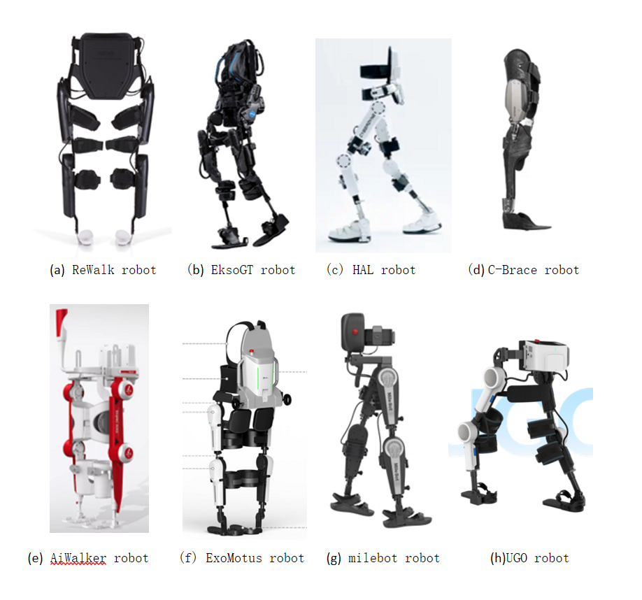
Figure 1: Lower limb exoskeleton rehabilitation robot
3. Kinematic Analysis of Lower Limb Exoskeleton Robots
(Kinematic analysis produces mathematical models, a two-bar linkage structure, driven by the hip and knee joints, analyzing position, velocity, acceleration, and force)
To analyze the mechanical model of a lower limb exoskeleton robot, one side of the robot can be simplified into a 6-degree-of-freedom system, which consists of two 3-degree-of-freedom linkages. The model parameters are shown in Table 1.
Table 1: DH Parameters Table
Connecting rod | \( {α_{i}} \) | \( {a_{i}} \) | \( {d_{i}} \) | \( {θ_{i}} \) |
1 | 0 | \( {l_{1}} \) | 0 | \( {q_{1}} \) |
2 | 0 | \( {l_{2}} \) | 0 | \( {q_{2}} \) |
Using the Denavit-Hartenberg (D-H) method, the kinematic model of the system is established with \( {O_{0}}-{X_{0}}{Y_{0}}{Z_{0}} \) as the absolute coordinate system and \( {O_{i}}-{X_{i}}{Y_{i}}{Z_{i}} \) as the coordinate system for the i-th joint of the lower limb exoskeleton robot. We assume the coordinate systems for the hip joint and ankle joint are \( {A_{1}}{ and A_{2}} \) ,and \( {θ_{i}} \) represents the relative rotation angles of each joint. From this, we can obtain the pose transformation matrices for each joint:
\( A_{1}^{0}=[\begin{matrix}\begin{matrix}{c_{1}} & -{s_{1}} & 0 & {l_{1}}{c_{1}} \\ {s_{1}} & {c_{1}} & 0 & {l_{1}}{s_{1}} \\ 0 & 0 & 1 & 0 \\ 0 & 0 & 0 & 1 \\ \end{matrix} \\ \end{matrix}] \) (1)
\( A_{2}^{1}=[\begin{matrix}{c_{2}} & -{s_{2}} & 0 & {l_{1}}{c_{1}} \\ {s_{2}} & {c_{2}} & 0 & {l_{1}}{s_{1}} \\ 0 & 0 & 1 & 0 \\ 0 & 0 & 0 & 1 \\ \end{matrix}] \) (2)
Thus, the pose transformation matrix of the ankle joint relative to the absolute coordinate system is:
\( T_{2}^{0}=A_{1}^{0}A_{1}^{2}[\begin{matrix}{c_{12}} & -{s_{12}} & 0 & {l_{1}}{c_{1}}+{l_{2}}{c_{12}} \\ {s_{12}} & {c_{12}} & 0 & {l_{1}}{s_{1}}+{l_{2}}{s_{12}} \\ 0 & 0 & 1 & 0 \\ 0 & 0 & 0 & 1 \\ \end{matrix}] \) (3)
Where \( {c_{1}}=cos{q_{1}} \) ; \( {c_{2}} \) =cos \( {q_{2}} \) ; \( {s_{1}}=sin{q_{1}} \) ; \( {s_{2}} \) =sin \( {q_{2}} \) ;
\( {c_{12}}=cos({q_{1}}+{q_{2}}) \) ; \( {s_{12}}=sin({q_{1}}+{q_{2}}) \) 。
According to the above formula, we can derive the attitude transformation matrix of the coordinate system:
\( {R_{1}}=(\begin{matrix}{c_{1}} & -{s_{1}} & 0 \\ {s_{1}} & {c_{1}} & 0 \\ 0 & 0 & 1 \\ \end{matrix}) \) (4)
\( {R_{2}}=(\begin{matrix}{c_{12}} & -{s_{12}} & 0 \\ {s_{12}} & {c_{12}} & 0 \\ 0 & 0 & 1 \\ \end{matrix}) \) (5)
The position vector of the coordinate system is:
\( {O_{1}}=(\begin{matrix}{l_{1}}{c_{1}} \\ {l_{1}}{s_{1}} \\ 0 \\ \end{matrix}) \) (6)
\( {O_{2}}=(\begin{matrix}{l_{1}}{c_{1}}+{l_{2}}{c_{12}} \\ {l_{1}}{s_{1}}+{l_{2}}{s_{12}} \\ 0 \\ \end{matrix}) \) (7)
The Jacobian matrix between the various joints is:
\( {J_{2}} \) = \( (\begin{matrix}{J_{v1}} & {J_{v2}} \\ {J_{w1}} & {J_{w2}} \\ \end{matrix}) \)
= \( [\begin{matrix}(\begin{matrix}0 \\ 0 \\ 1 \\ \end{matrix})×(\begin{matrix}{O_{2}}-{O_{0}} \\ \end{matrix}) & (\begin{matrix}0 \\ 0 \\ 1 \\ \end{matrix})×(\begin{matrix}{O_{2}}-{O_{1}} \\ \end{matrix}) \\ (\begin{matrix}0 \\ 0 \\ 1 \\ \end{matrix}) & (\begin{matrix}0 \\ 0 \\ 1 \\ \end{matrix}) \\ \end{matrix}] \)
\( (\begin{matrix}-{l_{1}}{s_{1}}-{l_{2}}{s_{12}} & -{l_{2}}{s_{12}} \\ {l_{1}}{c_{1}}-{l_{2}}{c_{12}} & {l_{2}}{c_{12}} \\ 0 & 0 \\ 0 & 0 \\ 0 & 0 \\ 1 & 1 \\ \end{matrix}) \) (8)
et the coordinates of the first and second link be \( {c_{1}} \) and \( {c_{2}} \) . Similarly, the position vectors of the centroids of the two links can be obtained as follows:
\( {O_{c1}}=(\begin{matrix}{l_{c1}}{c_{1}} \\ {l_{c1}}{s_{1}} \\ 0 \\ \end{matrix}) \) (9)
\( {O_{c1}}=(\begin{matrix}{l_{c1}}{c_{1}}+{l_{c2}}{c_{12}} \\ {l_{1}}{s_{1}}+{l_{c2}}{s_{12}} \\ 0 \\ \end{matrix}) \) (10)
The Jacobian matrix is:
\( {J_{c1}}=(\begin{matrix}-{l_{c1}}{s_{1}} & 0 \\ {l_{c1}}{c_{1}} & 0 \\ 0 & 0 \\ 0 & 0 \\ 0 & 0 \\ 1 & 0 \\ \end{matrix}) \) (11)
\( {J_{c2}}=(\begin{matrix}-{l_{1}}{s_{1}}-{l_{c2}}{s_{12}} & -{l_{c2}}{s_{12}} \\ {l_{1}}{c_{1}}+{l_{c2}}{c_{12}} & {l_{c2}}{c_{12}} \\ 0 & 0 \\ 0 & 0 \\ 0 & 0 \\ 1 & 1 \\ \end{matrix}) \) (12)
4. Dynamic Analysis of Lower Limb Exoskeleton Robots
To analyze the dynamics of the lower limb exoskeleton robot, we establish the Lagrangian dynamics equation for a single leg of the robot as follows:
\( M(q)\ddot{q}+C(q,\dot{q})\dot{q}+G(q)=τ \) (13)
Where \( M(q) \) is the positive definite inertia matrix, \( C(q,\dot{q}) \) represents the centripetal and Coriolis forces, and \( G(q) \) is the gravity matrix.
Calculation of Kinetic Energy:
\( K=\frac{1}{2}m{v^{T}}v+\frac{1}{2}{w^{T}}Iw \) (14)
\( {v_{i}}={J_{vi}}\dot{q} \) , \( {w_{i}}={J_{wi}}\dot{q} \) ;Substituting these gives:
\( K=\frac{1}{2}{\dot{q}^{T}}[\sum _{i=1}^{2}\lbrace {m_{i}}+J_{vi}^{T}{J_{vi}}+J_{wi}^{T}{R_{i}}I{R^{T}}{J_{wi}}\rbrace ]\dot{q}=\frac{1}{2}{\dot{q}^{T}}M\dot{q} \) (15)
After calculations, we define:
\( M=[\begin{matrix}{m_{1}}l_{c1}^{2}+{m_{2}}(l_{1}^{2}+l_{c2}^{2}+2{l_{1}}{l_{c2}}{c_{2}})+{I_{zz1}}+{I_{zz2}} & {m_{2}}(l_{c2}^{2}+{l_{1}}{l_{c2}}{c_{2}})+{I_{zz2}} \\ {m_{2}}(l_{c2}^{2}+{l_{1}}{l_{c2}}{c_{2}})+{I_{zz2}} & {m_{2}}l_{c2}^{2}+{I_{zz2}} \\ \end{matrix}] \) (16)
\( {c_{ijk}}≜\frac{1}{2}\lbrace \frac{∂{m_{kj}}}{∂{q_{i}}}+\frac{∂{m_{ki}}}{∂{q_{j}}}-\frac{∂{m_{ij}}}{∂{q_{k}}}\rbrace \) ; Thus, for a fixed \( k \) ,we have \( {c_{ijk}}={c_{jik}} \) ;
So we defined the \( (k,j) \) element in the matrix \( C(q,\dot{q}) \) as:
\( {c_{kj}}=\sum _{i=1}^{n}{c_{ijk}}(q){\dot{q}_{i}}=\sum _{i=1}^{n}\frac{1}{2}\lbrace \frac{∂{m_{kj}}}{∂{q_{i}}}+\frac{∂{m_{ki}}}{∂{q_{j}}}-\frac{∂{m_{ij}}}{∂{q_{k}}}\rbrace {\dot{q}_{i}} \) (17)
\( \begin{cases} \begin{array}{c} {c_{111}}=\frac{1}{2}\lbrace \frac{∂{m_{11}}}{∂{q_{1}}}+\frac{∂{m_{11}}}{∂{q_{1}}}-\frac{∂{m_{11}}}{∂{q_{1}}}\rbrace =0 \\ {c_{121}}={c_{211}}=\frac{1}{2}\lbrace \frac{∂{m_{12}}}{∂{q_{1}}}+\frac{∂{m_{11}}}{∂{q_{2}}}-\frac{∂{m_{12}}}{∂{q_{1}}}\rbrace =-{m_{2}}{l_{1}}{l_{c2}}{s_{2}} \\ {c_{221}}=\frac{1}{2}\lbrace \frac{∂{m_{12}}}{∂{q_{2}}}+\frac{∂{m_{12}}}{∂{q_{2}}}-\frac{∂{m_{22}}}{∂{q_{1}}}\rbrace =-{m_{2}}{l_{1}}{l_{c2}}{s_{2}} \\ {c_{112}}=\frac{1}{2}\lbrace \frac{∂{m_{21}}}{∂{q_{1}}}+\frac{∂{m_{21}}}{∂{q_{1}}}-\frac{∂{m_{11}}}{∂{q_{2}}}\rbrace =-{m_{2}}{l_{1}}{l_{c2}}{s_{2}} \\ {c_{122}}={c_{212}}=\frac{1}{2}\lbrace \frac{∂{m_{12}}}{∂{q_{1}}}+\frac{∂{m_{11}}}{∂{q_{2}}}-\frac{∂{m_{12}}}{∂{q_{1}}}\rbrace =0 \\ {c_{222}}=\frac{1}{2}\lbrace \frac{∂{m_{22}}}{∂{q_{2}}}+\frac{∂{m_{22}}}{∂{q_{2}}}-\frac{∂{m_{22}}}{∂{q_{2}}}\rbrace =0 \end{array} \end{cases} \) (18)
\( \begin{cases} \begin{array}{c} {c_{11}}={c_{111}}{\dot{q}_{1}}+{c_{211}}{\dot{q}_{2}},{c_{12}}={c_{121}}{\dot{q}_{1}}+{c_{221}}{\dot{q}_{2}} \\ {c_{21}}={c_{112}}{\dot{q}_{1}}+{c_{212}}{\dot{q}_{2}},{c_{22}}={c_{122}}{\dot{q}_{1}}+{c_{222}}{\dot{q}_{2}} \end{array} \end{cases} \) (19)
\( C=[\begin{matrix}-{m_{2}}{l_{1}}{l_{c2}}{s_{2}}{\dot{q}_{2}} & -{m_{2}}{l_{1}}{l_{c2}}{s_{2}}({\dot{q}_{1}}+{\dot{q}_{2}}) \\ {m_{2}}{l_{1}}{l_{c2}}{s_{2}}{\dot{q}_{1}} & 0 \\ \end{matrix}] \) (20)
The total potential energy of the two links is given by:
\( {m_{1}}g{l_{c1}}{s_{1}}+{m_{2}}g{(l_{1}}{s_{1}}+{l_{c2}}{s_{12}}) \) (21)
The gravity matrix is:
\( [\begin{matrix}\frac{∂P}{∂{q_{1}}} \\ \frac{∂P}{∂{q_{2}}} \\ \end{matrix}]=[\begin{matrix}({m_{1}}{l_{c1}}+{m_{2}}{l_{1}})g{c_{1}}+{m_{2}}{l_{c2}}g{c_{12}} \\ {m_{2}}{l_{c2}}g{c_{12}} \\ \end{matrix}] \) (22)
Substituting into the equation yields the joint control torque as:
\( {M_{1}}={\ddot{q}_{2}}({I_{2}}+{m_{2}}l_{c2}^{2}+{m_{2}}{l_{1}}cos({q_{2}}){l_{c2}})+{\ddot{q}_{1}}({I_{1}}+{I_{2}}+{m_{2}}(l_{1}^{2}+2cos{(q_{2}}){l_{1}}{l_{c2}}+l_{c2}^{2})+{m_{1}}l_{c1}^{2})+cos({q_{1}})({m_{2}}{l_{1}}+{m_{1}}{l_{c1}})g+{m_{2}}g{l_{c2}}cos({q_{1}}+{q_{2}})-{l_{1}}{l_{c2}}{m_{2}}{\dot{q}_{1}}{\dot{q}_{2}}sin({q_{2}}) \)
\( -{l_{1}}{l_{c2}}{m_{2}}{\dot{q}_{2}} sin({q_{2}})({\dot{q}_{1}}+{\dot{q}_{2}}) \) (23)
\( {M_{2}} \) = \( {l_{1}}{l_{c2}}{m_{2}}sin{({q_{2}})}\dot{q}_{1}^{2}+{\ddot{q}_{1}}({I_{2}}+{m_{2}}(l_{c2}^{2}+{l_{1}}cos{({q_{2}})}{l_{c2}})) \)
\( +{\ddot{q}_{2}}({m_{2}}l_{c2}^{2}+{I_{2}})+{l_{c2}}g{m_{2}}cos({q_{1}}+{q_{2}}) \) (24)
5. Interaction Control Algorithms for Lower Limb Exoskeleton Robots
The control strategies for lower limb exoskeleton robots can be roughly classified based on different input signal sources into position control, force information control, bioelectric signal control, and intelligent recognition control.
Position-based control strategies can be divided into trajectory tracking control and pelvic control. Trajectory tracking control involves pre-acquiring gait trajectories of normal walking, guiding the exoskeleton to move along the predetermined path, thus assisting patients with passive gait training. This method ensures the repeatability and continuity of rehabilitation training, making it suitable for early recovery; however, it cannot respond to sudden changes in gait and usually requires additional assistive devices. Pelvic control is proposed based on trajectory tracking control; by detecting the position and changes of the pelvis during walking, it aims to further optimize gait. Position-based control methods exhibit high stability but require accurate gait planning and precise human-machine interaction models.
Force information-based control strategies achieve dynamic control of the exoskeleton by monitoring and adjusting the force information between humans and machines. This mainly includes impedance control, force/position hybrid control, sensitivity amplification control, zero moment point (ZMP) control, and ground reaction force (GRF) control. Impedance control adjusts the relationship between the exoskeleton's motion trajectory and force feedback, allowing the robot to interact more naturally with the wearer and reducing impact forces on the patient. Force/position hybrid control further separates the control of the robot's position and main drive, enabling real-time adjustments to meet both position and force requirements in complex situations. Sensitivity amplification control enhances the exoskeleton's sensitivity to external forces, allowing the patient to exert less force to control the exoskeleton, thereby reducing their burden. ZMP control ensures that the exoskeleton's zero moment point remains within a stable region to maintain overall balance and stability, and it is widely used in posture and balance control. GRF control matches the ground reaction forces of the human and exoskeleton, continuously measuring all related motion characteristics to ensure synchronous movement. Force information-based control strategies can provide higher system compliance and dynamic adaptability; however, they tend to complicate the motion model and have higher demands for sensor and system real-time responsiveness.
Bioelectric signal-based control strategies utilize bioelectric signals such as electromyography (EMG) and electroencephalography (EEG) to predict and respond to the wearer’s movement intentions. EMG control directly predicts human movement intentions by detecting electrical signals generated by muscle activity, enabling rapid responses of the exoskeleton to changes in gait. This method significantly reduces control latency and improves adaptability to complex movements. However, EMG signals are susceptible to interference from movement and changes in sensor positioning, requiring precise sensor placement. EEG control uses electrical signals generated by the brain to control the exoskeleton, offering the advantage of not being limited by limb functionality; as long as the brain can generate movement signals, it can drive the exoskeleton. However, this method is vulnerable to interference from other bioelectric signals, necessitating high levels of attention from the patient.
Intelligent control strategies combine advanced control techniques such as fuzzy control and neural network control to handle complex nonlinear systems without the need for precise mathematical modeling. Fuzzy control employs various learning algorithms, enabling the exoskeleton robot to flexibly manage dynamic and complex environments. Neural network control learns and approximates the dynamic characteristics of the system, allowing for control of complex nonlinear relationships and adaptive adjustments to control strategies in response to system uncertainties, optimizing control accuracy. The greatest advantage of intelligent control lies in its adaptability and sensitivity to dynamic changes in the system, though it requires high technical demands for training and optimizing the control model during design and implementation.
6. Discussion and Conclusion
Lower limb exoskeleton rehabilitation robots incorporate various control strategies, including position-based, force information-based, bioelectric signal-based, and intelligent control methods, each with distinct characteristics and application advantages. Position-based control, such as trajectory tracking and pelvic control, is suitable for stable repetitive training but offers limited flexibility. Force information-based control strategies improve system compliance through real-time adjustments of the human-machine interaction forces, but they demand a high number of sensors and rapid system responsiveness. Bioelectric signal control, such as EMG and EEG, can quickly capture patients' movement intentions, providing a more direct control approach; however, it is susceptible to external interference, making the stability of signal acquisition crucial. Intelligent control strategies, which combine algorithms like fuzzy control and neural networks, possess the capability to handle complex nonlinear systems and can adaptively adjust; however, they require substantial data support and model optimization.
Future development should focus on composite control strategies that integrate multiple control methods to achieve better system performance and responsiveness. Additionally, personalized and intelligent control strategies will further enhance the rehabilitation effectiveness of exoskeleton robots, catering to the diverse needs of different patients. With advancements in technology and continuous optimization of control algorithms, exoskeleton robots will play an increasingly important role in the rehabilitation field, providing patients with more efficient and intelligent rehabilitation solutions.
References
[1]. Ferreira, J. P., Dong, W., & Zhang, X. (2022). A review on the rehabilitation exoskeletons for the lower limbs of the elderly and the disabled. Electronics, 11(3), 388.
[2]. Li, W. T., Liu, K. P., & Sun, Z. B. (2022). Development and evaluation of a wearable lower limb rehabilitation robot. Journal of Bionic Engineering, 19, 688–699.
[3]. Dobkin, B. H., & Duncan, P. W. (2012). Should body weight–supported treadmill training and robotic-assistive steppers for locomotor training trot back to the starting gate? Neurorehabilitation and Neural Repair, 26(4), 308–317.
[4]. Tefertiller, C., Pharo, B., Evans, N., & Winchester, P. (2011). Efficacy of rehabilitation robotics for walking training in neurological disorders: A review. Journal of Rehabilitation Research and Development, 48(4), 387–396.
[5]. Veneman, J. F., Kruidhof, R., Hekman, E. E. G., Van Asseldonk, E. H. F., & Van Der Kooij, H. (2007). Design and evaluation of the LOPES exoskeleton robot for interactive gait rehabilitation. IEEE Transactions on Neural Systems and Rehabilitation Engineering, 15(3), 379–386.
[6]. Kawamoto, H., Hayashi, T., Sakurai, T., Eguchi, K., & Sankai, Y. (2009). Development of single leg version of HAL for hemiplegia. In IEEE Annual International Conference of the Engineering in Medicine and Biology Society (pp. 5038–5043).
[7]. Zhou, L. B., Chen, W. H., Wang, J. H., Bai, S. P., Yu, H. Y., & Zhang, Y. P. (2018). A novel precision measuring parallel mechanism for the closed-loop control of a biologically inspired lower limb exoskeleton. IEEE/ASME Transactions on Mechatronics, 23(6), 2693–2703.
Cite this article
Wang,J. (2025). Research on Interactive Control Algorithms for Lower Limb Exoskeleton Rehabilitation Robots. Applied and Computational Engineering,125,32-39.
Data availability
The datasets used and/or analyzed during the current study will be available from the authors upon reasonable request.
Disclaimer/Publisher's Note
The statements, opinions and data contained in all publications are solely those of the individual author(s) and contributor(s) and not of EWA Publishing and/or the editor(s). EWA Publishing and/or the editor(s) disclaim responsibility for any injury to people or property resulting from any ideas, methods, instructions or products referred to in the content.
About volume
Volume title: Proceedings of the 3rd International Conference on Mechatronics and Smart Systems
© 2024 by the author(s). Licensee EWA Publishing, Oxford, UK. This article is an open access article distributed under the terms and
conditions of the Creative Commons Attribution (CC BY) license. Authors who
publish this series agree to the following terms:
1. Authors retain copyright and grant the series right of first publication with the work simultaneously licensed under a Creative Commons
Attribution License that allows others to share the work with an acknowledgment of the work's authorship and initial publication in this
series.
2. Authors are able to enter into separate, additional contractual arrangements for the non-exclusive distribution of the series's published
version of the work (e.g., post it to an institutional repository or publish it in a book), with an acknowledgment of its initial
publication in this series.
3. Authors are permitted and encouraged to post their work online (e.g., in institutional repositories or on their website) prior to and
during the submission process, as it can lead to productive exchanges, as well as earlier and greater citation of published work (See
Open access policy for details).
References
[1]. Ferreira, J. P., Dong, W., & Zhang, X. (2022). A review on the rehabilitation exoskeletons for the lower limbs of the elderly and the disabled. Electronics, 11(3), 388.
[2]. Li, W. T., Liu, K. P., & Sun, Z. B. (2022). Development and evaluation of a wearable lower limb rehabilitation robot. Journal of Bionic Engineering, 19, 688–699.
[3]. Dobkin, B. H., & Duncan, P. W. (2012). Should body weight–supported treadmill training and robotic-assistive steppers for locomotor training trot back to the starting gate? Neurorehabilitation and Neural Repair, 26(4), 308–317.
[4]. Tefertiller, C., Pharo, B., Evans, N., & Winchester, P. (2011). Efficacy of rehabilitation robotics for walking training in neurological disorders: A review. Journal of Rehabilitation Research and Development, 48(4), 387–396.
[5]. Veneman, J. F., Kruidhof, R., Hekman, E. E. G., Van Asseldonk, E. H. F., & Van Der Kooij, H. (2007). Design and evaluation of the LOPES exoskeleton robot for interactive gait rehabilitation. IEEE Transactions on Neural Systems and Rehabilitation Engineering, 15(3), 379–386.
[6]. Kawamoto, H., Hayashi, T., Sakurai, T., Eguchi, K., & Sankai, Y. (2009). Development of single leg version of HAL for hemiplegia. In IEEE Annual International Conference of the Engineering in Medicine and Biology Society (pp. 5038–5043).
[7]. Zhou, L. B., Chen, W. H., Wang, J. H., Bai, S. P., Yu, H. Y., & Zhang, Y. P. (2018). A novel precision measuring parallel mechanism for the closed-loop control of a biologically inspired lower limb exoskeleton. IEEE/ASME Transactions on Mechatronics, 23(6), 2693–2703.