


1. Introduction
In line with the modern emphasis on low-carbon environmental protection, countries have focused on the development of renewable energy, including solar, wind, and hydrogen energy. The significance of these new energy sources lies in following aspects: they increase the number of energy resources and reduce dependence on traditional fossil fuels, and they contribute to lower the greenhouse effect and minimizing environmental pollution [1]. The field of new energy power generation is experiencing rapid growth. Solar and wind energy can be generated in most areas and eco-friendly. But they can be influenced by climatic conditions. Ocean energy and biomass energy hold potential, but technological advancements are necessary for their wider application. Geothermal energy is stable and reliable but is geographically constrained, which limit its promotion. Nuclear energy is efficient and clean but has problems related to safety and pollution aspects. Although the renewable energy sources mentioned has all kinds of characteristics, solar power generation remains the primary focus of development. Each major new energy power generation system has unique structural characteristics. Solar power systems consist of solar cell arrays, controllers, batteries, and converters, converting solar energy into electrical energy through the photoelectric effect. Wind power systems include turbines, generators, towers, and control systems, harnessing wind to drive turbine rotation and generate electricity. Ocean energy systems typically involve floating devices like buoys and anchor chains, converting wave or temperature difference energy into electrical energy. Nuclear power systems are comprised of nuclear reactors, steam generators, turbines, and generators, utilizing nuclear fission to produce thermal energy and convert it into electrical energy. Additionally, biomass and geothermal power systems convert natural energy into electrical energy through various physical or chemical processes, supporting sustainable development. These systems form a diversified new energy power generation system.
The application of impedance source converters (ISCs) and quasi-Z-source converters (QZSCs) enhances energy conversion and efficiency, reduces losses during energy conversion and improving overall system energy efficiency. They promote the use of clean energy, reduce dependence on traditional energy sources, and drive the sustainable development of power systems because of their characteristics mentioned. However, integrating new energy into power systems presents challenges such as intermittency and slow dynamic response. In many cases, extra energy storage devices are necessary for hybrid power supply [2]. A new energy hybrid power supply system based on a three-port converter requires only an integrated three-port converter, offering benefits like compact size, cost-effectiveness, high integration, and convenient control [3]. By combining the boosting capabilities of QZSC and switched-capacitor structures, a high-gain three-port converter has been developed. In energy storage systems, hydrogen-electric hybrid fuel cells face issues with mismatch between their output voltage and bus voltage, necessitating DC-DC converters for voltage decoupling [4]. Researchers have developed a QZSC DC-DC converter with wider voltage range, which can balance wide input voltage range, continuous input current, and common ground for input and output. Traditional energy storage systems often feature two-stage structures: voltage source converters and separate bidirectional DC/DC converters, increasing total cost, volume, and control complexity. Researchers have developed a hybrid energy storage system (HESS) based on a bidirectional QZSC, significantly improving power density, dynamic response, and reliability compared to single energy storage systems [5].
Many scholars have developed converters using coupled inductors, switched inductors, switched capacitors, and hybrid switched inductor-capacitors. However, achieving high voltage gain often causes some disadvantages such as increased volume, cost, and complex structure [6]. To achieve high voltage gain and low voltage stress in converters, high-gain DC-DC boost QZSCs offer advantages such as high voltage gain and low component voltage stress through voltage gain and component voltage stress calculations, system stability analysis, and research [7]. Traditional two-level converters have some disadvantages. Firstly, they can only step-down voltage. If voltage step-up is required, an additional boosting stage (like a boosting DC-DC converter) will be necessary. This will increase system complexity and losses. Secondly, simultaneous conduction of the upper and lower arm switching devices in a traditional two-level converter can cause short circuits, which will reduce system reliability and damage power devices. Furthermore, traditional two-level converters have limited adaptability under high voltage and power requirements. Lastly, they tend to generate significant electromagnetic interference. So, the system will need additional filters.
Impedance source converters solve these issues by incorporating impedance networks. Firstly, they enable single-stage voltage step-up and step-down, simplifying the system structure and eliminating the need for additional hardware. Secondly, they allow switching devices to conduct simultaneously without causing short circuits, significantly enhancing system’s reliability. Additionally, their expansibility makes them suitable for various power electronics applications, such as renewable energy generation and electric vehicles’ energy systems. Finally, the unique structure and operating mode of impedance source converters effectively reduce electromagnetic interference, simplifying the design process.
The Z-source converter stands as a prominent power electronic device, renowned for its unique voltage conversion capabilities and versatility, enhancing system reliability. This overview aids power electronics researchers and engineers in selecting suitable topologies based on their benefits, drawbacks, and applications.
2. Z-Source Converters
2.1. Basic Z-Source Converters
The Z-source converter (ZSC) stands as a highly promising power electronic device in current technological areas. Its defining characteristic lies in an X-shaped circuitry comprising 2 capacitors and 2 inductors, interconnected to form an impedance source (Z-source) network, as shown in Figure 1. This network serves as a bridge between the main converter circuit and the DC input source.
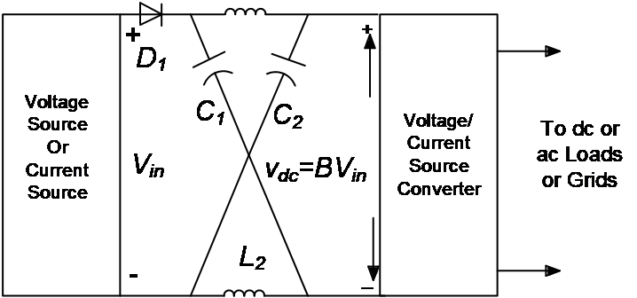
Figure 1: Topology of Z-source converter [8].
When compared to other power electronic converters, the Z-source converter discussed here offers several advantages as follows [8].
• Distinct buck-boost capability: thanks to its Z-source network, the ZSC can seamlessly achieve voltage bucking and boosting without the need for supplementary DC buck-boost stages. This trait offers significant versatility in voltage regulation.
• Elevated system reliability: the ZSC's design permits simultaneous conduction of devices on the converter bridge arms (shoot-through state). This circumvents issues linked to dead-time insertion in traditional converters, which aim to prevent shoot-through on the same bridge arm. Consequently, harmonic contamination of the output sine wave is minimized. Furthermore, during the shoot-through phase, the bridge arm devices' current rise is controllable, thereby effectively safeguarding against component damage.
• Expanded application spectrum: with its extensive buck-boost range and high reliability, the ZSC finds application in diverse fields where output voltage fluctuations are significant due to load and environmental variables. These include AC speed control systems, fuel cell power supply systems, distributed power generation systems (such as photovoltaic and wind power), and microgrids. In distributed power generation systems, the ZSC can substitute traditional Boost circuits and voltage-source converters, thereby simplifying system architecture.
However, the fundamental Z-source converter exhibits certain drawbacks:
• Interrupted input current and elevated capacitor voltage stress: during the shoot-through state, the inductors within the Z-source network undergo charging and discharging cycles, potentially distorting the input current waveform in the boost mode of the ZSC. Simultaneously, in boost mode, the capacitors are subjected to heightened voltage levels, necessitating meticulous selection based on their voltage withstand capabilities, which subsequently elevates costs.
• Intricate control strategy: this complexity manifests in the multitude of control parameters and sluggish dynamic response. Achieving stable voltage output necessitates the adjustment of various interdependent control parameters, such as the shoot-through duty cycle and modulation index. Moreover, the presence of the Z-source network may necessitate an extended period for the system to revert to a stable state under abrupt load variations or significant input voltage fluctuations.
• Efficiency concerns: the charging and discharging processes of the inductors and capacitors in the ZSC introduce certain energy losses, impacting the converter's overall efficiency. These losses are exacerbated under high-frequency operating conditions. Furthermore, due to the ZSC's intricate energy conversion process, structure, and control strategy, its conversion efficiency may lag other converter types in specific environments, such as high-frequency operation, frequent load changes, and substantial input voltage fluctuations.
2.2. Bidirectional Z-Source Converter
To mitigate the disadvantages, several modified ZSC circuits have been devised.
One such modification is the bidirectional Z-source converter (BZSC), derived from the basic ZSC, as depicted in the figure 2. This transformation involves substituting the input diode D with a bidirectional switch S7. This modification empowers the ZSC, which was originally limited to DC-AC conversion, to achieve bidirectional energy flow, encompassing both DC-AC and AC-DC conversions. The enhancement improves the system's energy utilization efficiency and flexibility. In addition to inheriting all the advantages of the ZSC, bidirectional Z-source converters are particularly well-suited for motor control systems necessitating frequent start-stops or speed adjustments. For instance, in applications such as electric vehicles, wind power generation, and elevator systems, the regenerative mode of the BZSC can capture energy during braking and feed it back to the battery or grid, thereby augmenting the system's energy utilization efficiency and economic viability. However, BZSC also presents challenges, as the already intricate control strategy becomes even more sophisticated to accommodate bidirectional energy flow.
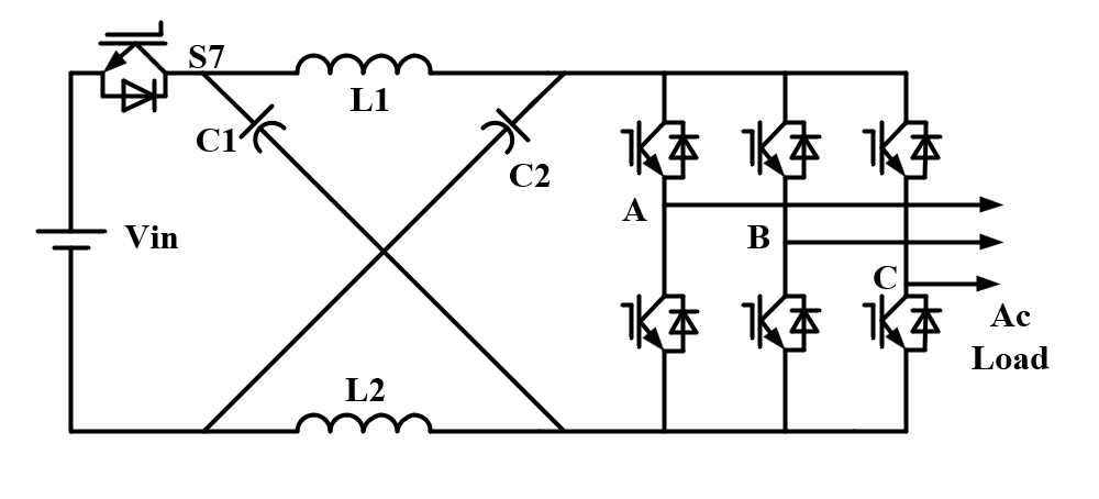
Figure 2: Topology of BZSC [8].
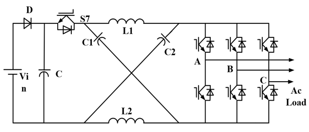
Figure 3: Topology of HP-ZSC [8].
2.3. High-Performance Z-Source Converter
Figure 3 depicts a high-performance Z-source converter (HP-ZSC) that incorporates an additional capacitor C and a bidirectional switch S7 to the fundamental ZSC configuration. This enhancement facilitates stable operation across an expanded load range, markedly mitigating or eliminating potential DC link voltage fluctuations during load variations. Furthermore, it permits the utilization of smaller inductors within the Z-network. However, both the HP-ZSC and bidirectional Z-source converter (BZSC) exhibit comparable drawbacks: they entail heightened complexity and cost stemming from the introduction of extra components, necessitating sophisticated algorithms and meticulous parameter tuning for converter functionality.
2.4. Quasi Z-Source Converter
When confronted with insufficient DC power supply voltage to meet the required output voltage, traditional Voltage Source Converters (VSCs) and Current Source Converters (CSCs) encounter comparable limitations. In VSCs, the voltage in DC-side may fail to satisfy the threshold necessary for direct inversion to the desired AC voltage, necessitating supplementary boost or buck stages for voltage adjustment. Conversely, CSCs exhibit relatively high internal resistance, which can induce interference in current distribution among multiple motors during multi-motor operation, necessitating a two-stage structure. This, in turn, elevates system costs and control complexity. Consequently, Z-source networks and Quasi-Z-source networks were introduced, as shown in Figure 4. Both architectures incorporate two inductors (L1 and L2), two capacitors (C1 and C2), as well as a diode (D1), interconnected within the DC link of the converter. This configuration enables the converter to temporarily elevate its voltage through the internal exchange of energy between capacitors and inductors when the DC voltage is inadequate, thereby facilitating inversion to a higher AC voltage without the requirement for external, bulky voltage regulation equipment [9].
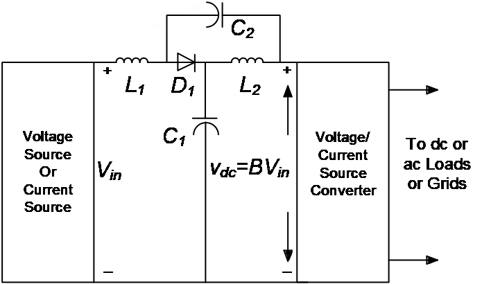
Figure 4: Topology of QZSC [9].
The QZSC retains every merit of the ZSC, including voltage boosting and bucking capabilities, compatibility with a broad range of input voltages, single-stage provision of the required voltage to loads or the grid, and management of shoot-through states. Additionally, the QZSC draws continuous current from the DC power supply, thereby alleviating input power stress, prolonging the lifespan of the input power supply, and rendering it suitable for power conversion in renewable energy systems. [10] Furthermore, the voltage across C2 in the QZSC is significantly lower than that in the ZSC, lessening component specifications. Moreover, the QZSC features a shared DC rail connecting both the input and output, facilitating easier assembly and mitigating electromagnetic interference. In terms of modulation techniques, the QZSC advances traditional Space Vector Modulation (SVM) methods, optimizing DC link voltage utilization, minimizing harmonic content, and enhancing stability.
2.5. Switched-Inductor Z-Source Converter
A novel Z-Source Converter topological structure, a three-phase, two-level voltage-source converter akin to traditional ZSCs, has been introduced. This technology is inspired by previously designed switched-capacitor (SC), switched-inductor (SL), and hybrid SC/SL type DC-DC converters. Therefore, the integration of the fundamental ZSC impedance network with advanced SL units has been implemented to form the pioneering SL-ZSC structure, as depicted in the figure, which offers exceptional voltage boosting and inversion capabilities, ultimately enhancing performance and facilitating its industrial applications [10].
The concept of the Switched-Inductor Z-Source Converter (SL-ZSC) can be applied across various power conversion scenarios, including DC-DC, DC-AC, AC-DC, and AC-AC conversions [14]. The SL-ZSC topology is compatible with all traditional modulation techniques, as shown in Figure 5. For clarity and simplicity, the Simple Boost Control (SBC) modulation technique, which is widely utilized, has been adopted in this context. Besides the standard three-phase sinusoidal pulse width modulation signals, additional signals such as positive DC signal (Vp) and negative DC signal (Vn) are introduced to generate supplementary shoot-through (ST) pulses. The switching operation of the impedance circuit facilitates energy storage and transfer between the capacitors and the DC bus.

Figure 5: Topology of SL-ZSC [10].
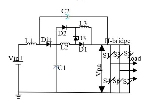
Figure 6: Topology of SL-QZSC [14].
2.6. Switched-Inductor quasi-ZSC
Since the advent of Z-Source Converters based on switched inductors/capacitors, there has been a surge in the number of new topological structures and improvements. Researchers are encouraged to explore innovative concepts and solutions leveraging this emerging technology. The quasi-structure represents a modification of the traditional ZSC converter, characterized by several distinct features. By incorporating an SL unit (L2 - L3 - D1 - D2 - D3) into the impedance network, the quasi-ZSC is configured into an SL-quasi structure, as illustrated in Figure 6. Unlike the traditional SL-ZSC, the inductor (L1) is directly connected to the input DC source, ensuring continuous input current and reducing stress on the source. The overall impedance network of the SL-QZSC is connected in series on the DC side, resulting in lower voltage stress on the capacitors, enhanced converter performance, and the provision of a common ground. This configuration minimizes leakage currents in photovoltaic applications.
2.7. Comparison Between Different ZSCs
SL-ZSC provides excellent voltage boosting and inversion capabilities, ultimately enhancing performance and promoting its industrial applications. BZSC is capable to ensure bidirectional energy exchange between AC and DC storage systems is cost-effective. HP-ZSC Eliminates the possibility of DC voltage link drop, and the small Z-network inductor operates over a wide load range. QZSC can be adapted to a wide range of input voltages, reduces the stress on the input power source, extends the life of the input power source, is suitable for power conversion of renewable energy, improves the traditional space vector modulation technology, increases the utilization rate of DC link voltage, and reduces harmonic content, enhances stability. The input current of SL-QZSC becomes continuous, reducing the stress on the source and reducing the leakage current in photovoltaic applications
3. Quasi-Z-Source Converters in Renewable Energy Directions
3.1. Three-Port Converter
Renewable energy hybrid power supply systems often grapple with the challenges of low input voltage and a wide voltage range, making it difficult to meet stable high-voltage load demands in practical power supply scenarios. However, three-port converters (TPC) provide a viable solution to these issues while also offering benefits such as compact size, cost-effectiveness, high efficiency, and compatibility with a broad input range [11].
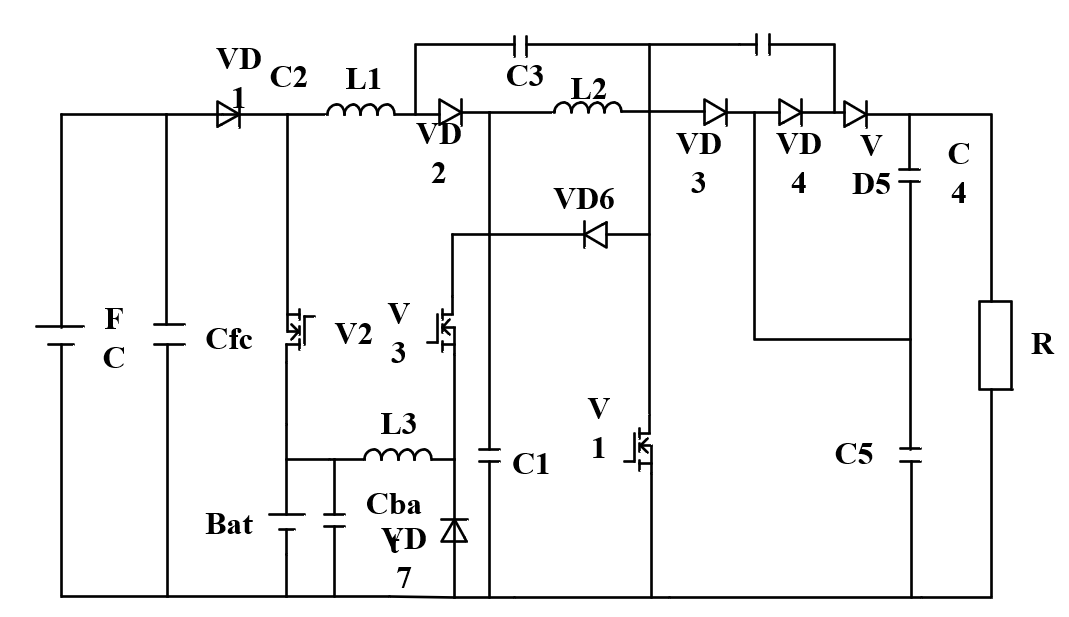
Figure 7: Topology of high-gain three-port converter [11].
Figure 7 introduce the topology structure of the high-gain TPC, which combines a quasi-Z-source and switched-capacitor configurations, specifically designed for a renewable energy port using fuel cells. Here, V1-V3 signify switching devices, VD1-VD7 represent diodes, L1-L3 denote inductors, and C1-C5, Cfc, and Cbat are capacitors. FC indicates the fuel cell port, Bat represents the battery port, and R signifies the load. The quasi-Z-source structure comprises L1, L2, C1, C2, and VD2, whereas the switched-capacitor structure is made up of C3-C5.
The high-gain TPC, which integrates a quasi-Z-source and switched-capacitor configurations, operates in three distinct modes based on power flow directions, as showed in Figure 8: Single-Input Single-Output (SISO) mode, Dual-Input Single-Output (DISO) mode, and Single-Input Dual-Output (SIDO) mode. Literature [15] defines the rated power of the fuel cell (FC), the power of the battery (Bat), and the load (R)’s power Pfc, Pbat, and Po, respectively. The operating mode of the TPC is switched according to these three power values.
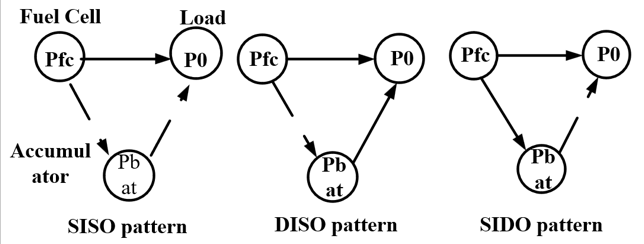
Figure 8: Power flow diagram of the three-port converter [11].
Based on the modal analysis conducted, the voltage gain expressions for both DISO and SISO modes, as well as SIDO mode (which shares the same gain expression with SISO mode due to dependency on D1 only), have been derived. Assuming the duty cycles of V1, V2, and V3 are D1, D2, and D3, respectively, the voltage gain expressions are as follows:
\( \begin{cases} \begin{array}{c} DISOmode:Uo=[2/((1-2D1) )]*[UbatD2+U{f_{c}}(1-D2)] \\ SIDO/SISOmode:Uo=[2/((1-2D1) )]*Ufc \end{array} \end{cases}\ \ \ (1) \)
These equations reveal that the proposed high-gain TPC, leveraging a quasi-Z-source and switched-capacitor configurations, offers superior voltage gains, a broader output voltage range, and necessitates a lower duty cycle compared to conventional Boost three-port converters and other high-gain alternatives. Figure 3 visually compares the voltage gain trends of the proposed converter with typical TPCs. While the converter boasts several advantages, it does possess a relatively intricate structure, necessitating complex control strategies and potentially higher losses due to the intricate energy conversion process in practical scenarios. However, as renewable energy technologies continue to advance and gain popularity, high-gain three-port converters are poised for increased application in the renewable energy sector.
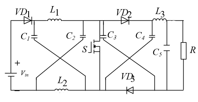
Figure 9: Topology of HSQZSC.
3.2. High-Step quasi-Z Source Converter
Figure 9 illustrates the topological structure of the high-step quasi-Z source converter (HSQZSC) converter. It comprises a power supply voltage input Vin, a quasi-Z-source impedance network (comprising inductors L1, L2, along with capacitors C1, C2), diodes VD1, VD2, VD3, capacitors C3, C4, a switching tube S, and a load R. Operating in current continuous mode minimizes input current ripple. The HSQZSC converter functions through two distinct working modes controlled by the switching tube S, each with its equivalent circuits and voltage/current directions for each component.
Based on the description provided, the equivalent circuit and operational principles of the HSQZSC converter in both working modes are outlined below:
• Working Mode 1: The switching tube S is turned on by a high-level signal. Power supply Vin charges capacitor C3 and supplies power to load R. Diode VD1 is forward-biased and conducts. Diodes VD2 and VD3 are cut off due to negative voltages across them according to Kirchhoff's voltage law (KVL). Currents in inductors L1 and L2 rise. Voltages across capacitors C1 and C2 decrease. Load R is powered by the power supply and capacitor C4.
• Working Mode 2: The switching tube S is turned off by a low-level signal. Capacitor C3 discharges, causing diode VD1 to be reverse-biased and cut off. Diode VD2 is forward-biased and conducts due to the discharge current of inductor L1 and the charging current of capacitor C2. Diode VD3 is forward-biased and conducts due to the charging current of capacitor C4 and the load current. Capacitor C3 controls the on and off states of diode VD1 through its charging and discharging states. Load R is supplied with voltage by power supply Vin and capacitors C1, C2, and C3. Capacitors C1 and C2 charge in parallel with inductors L1 and L2 respectively, resulting in an increase in the quasi-Z-source impedance network capacitor voltages.
Figure 10: Topology of TS-1 [12]. |
Figure 11: Topology of TS-2 [13]. |
Figure 12: Topology of TS-3 [14]. | |
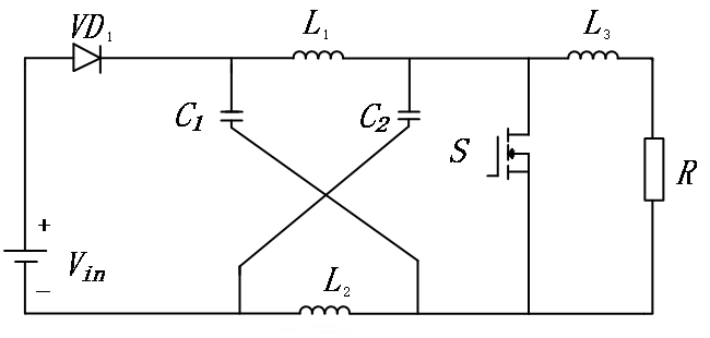
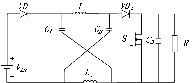
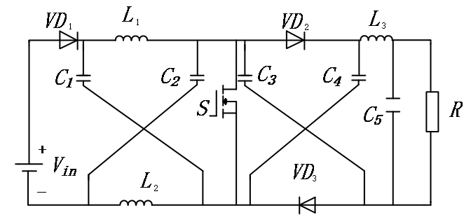
To validate the design merits of the HSQZSC converter topology, a comparative analysis is conducted with different Z-source boost converters, namely TS-1, TS-2, and TS-3. The topological configurations of these converters are depicted in Figure 10, Figure 11, and Figure 12, respectively [12-14]. The focus of the comparison is on key parameters, including voltage gain, input current ripple, efficiency, and control intricacy. The HSQZSC converter is anticipated to exhibit superior characteristics, such as elevated voltage gains, an expanded output voltage range, and potentially reduced duty cycle requirements, when compared to the control group converters. However, it is important to acknowledge that the intricate structure of the HSQZSC converter may necessitate the adoption of more sophisticated control methodologies and could potentially result in higher losses due to the owing to the complicated nature of the energy conversion process.
The control cohort encompasses the TS-1, TS-2, and TS-3 converters. A comparative analysis of the voltage gain (M) between this cohort and the HSQZSC converter reveals that the voltage gains of the control cohort incrementally rise by a factor of 1, whereas the HSQZSC converter's voltage gain begins to escalate by a factor of 2. Based on the voltage gain formulation, the HSQZSC converter consistently offers twice the voltage gain compared to the TS-1 converter. The TS-2 converter's voltage gain is notably inferior to that of the HSQZSC converter. As the duty cycle (D) surpasses 0.33, the TS-3 converter's voltage gain surpasses the HSQZSC converter's; however, for D values below 0.33, the HSQZSC converter's voltage gain is superior to that of the control cohort.
The voltage stress on the capacitors within the Z-source network of the control group (TS-1, TS-2, TS-3) and the HSQZSC converter is normalized relative to the input voltage (Vin). The relationship between capacitor voltage stress and duty cycle is graphically represented. It is evident that the capacitor voltage stress in the Z-source network of the control cohort converters (TS-1, TS-2, TS-3) increases uniformly from 1 times Vin, whereas the HSQZSC converter's stress gradually increases from 0 times Vin and remains consistently lower than the control cohort at equivalent duty cycles. Consequently, the HSQZSC converter boasts the advantage of reduced capacitor voltage stress compared to TS-1, TS-2, and TS-3.
The diode and switching tube voltage stresses (Vs and Vvd) are also normalized similarly and depicted. It is apparent that the Vs and Vvd of the control cohort converters (TS-1, TS-2, TS-3) and the HSOZSC converter all progressively increase from 1 times Vin. The trends of TS-1, TS-2, and HSQZSC converters are consistent at equivalent duty cycles, but their increase rate is faster than that of the TS-3 converter. Therefore, at equivalent duty cycles, the TS-3 converter exhibits relatively lower Vs and Vvd compared to TS-1, TS-2, and HSQZSC converters.
In summary, the HSQZSC converter surpasses the TS-1 and TS-2 converters regarding to voltage gain, capacitor voltage stress in the Z-source, and diode and switching tube voltage stresses at equivalent duty cycles. Although the TS-3 converter demonstrates lower Vs and Vvd, its high voltage gain necessitates a high duty cycle, and it comprises 8 inductors and capacitors, corresponding to the highest circuit order (8th order), thereby resulting in relatively lower power density. Hence, through the performance comparison between the control cohort converters (TS-1, TS-2, TS-3) and the HSQZSC converter, it is concluded that tons of benefits like high voltage gain, low capacitor voltage stress, and a relatively smaller component count are shown on the HSQZSC converter [13].
However, despite its numerous advantages, the HSQZSC converter also exhibits certain disadvantages in terms of circuit complexity, control strategy, and power loss. Firstly, in comparison to conventional DC-DC converters, the quasi-Z-source converter possesses a more intricate structure and necessitates extra parts (such as inductors, capacitors as well as diodes), thereby augmenting the challenges associated with design, manufacture, and maintenance. Secondly, the complex topology of the quasi-Z-source converter necessitates a correspondingly intricate management approach, requiring a sophisticated control algorithm and a higher-performance controller to ensure stable output and optimized performance. Lastly, its high gain is accompanied by elevated power loss, particularly in terms of conduction loss and switching loss of the components.
3.3. ZSC in Energy Storage System
In contrast to conventional QZSC and battery-assisted photovoltaic systems, the hybrid energy storage system (HESS) primarily utilizes the battery for average power provision. Consequently, an exploration of power circuits and switching methodologies across various modes is imperative.
As shown in Figure 13, three distinct power sources, as battery packs, supercapacitors, and motors, are interconnected via an impedance network. Regulation of battery power and motor operation is facilitated by the converter and V7, whereas synchronization of battery-motor discrepancies is achieved through the supercapacitor positioned on the input side. Research reveals that the supercapacitor and battery's average current are distributed according to the direct duty cycle. Given that the DC-side average current correlates with the converter's modulation ratio, power allocation can be modulated through the direct duty cycle and converter modulation ratio.
The operation modes are as following:
• Traction Mode: The motor's power requirements are met by both the supercapacitor and battery.
• Regenerative Mode: This represents the traction mode's reverse, where the motor redirects energy back into the storage system.
• Supercapacitor Energy Recovery Mode: In this mode, the battery supplies power to both the supercapacitor and motor.
By managing motor and battery power, residual energy is automatically steered towards the supercapacitor controller, comprising three components: the Frequency Domain Controller (FDC) and Battery Current Regulator (BCR). The FDC capitalizes on the battery and supercapacitor's frequency-domain complementarity: the battery fuels low-frequency power demands, while the supercapacitor handles high-frequency requirements.
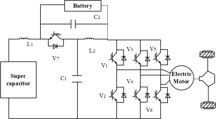
Figure 13: Configuration diagram of the QZSC in HESS [14].
4. Discussions
The Z-source converter stands as a prominent power electronic device, renowned for its unique voltage conversion capabilities and versatility, enhancing system reliability. Building on the ZSC, the QZSC offers benefits such as renewable energy compatibility, minimal component demands, simplified assembly, low electromagnetic interference, and high stability. This overview aids power electronics researchers and engineers in selecting suitable topologies based on their benefits, drawbacks, and applications. While current research converters face challenges like control strategy complexity, high losses in three-port converters and HESS due to intricate energy conversion processes, and elevated voltage stress in HSQZSC's diodes and switching tubes compared to TS-3 control groups, leading to insufficient system stability, ongoing research will progressively address these issues. Future converter research may concentrate on refining three-port converter control strategies and achieving soft-switching technology breakthroughs. For the HSQZSC, controller design will focus on simplifying control, enhancing stability, or modifying the topology to mitigate voltage stress. In battery energy storage, the emphasis will be on system simplification to cut costs, improving HESS economy and practicality. Technological advancements will streamline HESS integration, reducing component count and costs, while bolstering system reliability and maintainability, thereby simplifying control strategies.
5. Conclusion
This article examines the area of the structure, advantages, and application domains of the basic Z-source converter, and further examines the topological structures of its derivatives like BZSC, HP-ZSC, SL-ZSC, etc. Through innovative impedance network designs, it contributes significant advancements to power electronic conversion. The burgeoning new energy sector, particularly solar-based photovoltaic technology, necessitates step-up converters due to low photovoltaic array output voltages. Given the QZSC's efficient energy conversion, management, and other advantages, it aligns well with grid-connected converter DC-side voltage needs, heralding vast potential in new energy fields. This paper emphasizes QZSC applications in new energy power systems. The thesis presents the topological structure and working state analysis of a three-port converter tailored for new energy implementations, summarizes existing research, and contrasts it with the basic Z-source converter.
Authors Contribution
All the authors contributed equally and their names were listed in alphabetical order.
References
[1]. Zhu Y, Wen H, Tafti H et al., Novel Fast-Speed Partial-Shading-Tolerant Flexible Power Point Tracking for Photovoltaic Systems With Explicit Key Points Estimation [J]. IEEE Transactions on Sustainable Energy, 2024, 15(1): 466-485.
[2]. Cheraghi R, Adib E, Golsorkhi MS. A Non-isolated High Step-up Three-port Soft-switched Converter with Minimum Switches [J]. IEEE Transactions on Industrial Electronics, 2021, 68(10): 9358-9365.
[3]. Tian Q, Zhou G, Liu R, et al. Topology Synthesis of a Family of Integrated Three-port Converters for Renewable Energy System Applications [J]. IEEE Transactions on Industrial Electronics, 2021, 68(7): 5833-5846.
[4]. Zhang W, Xu L, Li J, et al. Comparison of Daily Operation Strategies for a Fuel Cell/Battery Tram [J]. International Journal of Hydrogen Energy, 2017, 42(29): 18532-18539.
[5]. Hu S, Wang Y, Cui W, et al. Research on Application of Hybrid Energy Storage System Based on Quasi-Z-source Converter [J]. Power Electronics, 2016, 50(11): 8-10.
[6]. Zhang Y, Gao Y P, Zhou L, et al. A Switched Capacitor Bidirectional DC-DC Converter with Wide Voltage Gain Range for Electric Vehicles with Hybrid Energy Sources [J]. IEEE Transactions on Power Electronics, 2018, 33(11): 9459-9469.
[7]. Zhang Tao, Hou Pengpeng, Wang Yaobin, et al. A Novel Quasi-Z-source High Step-up DC-DC Boost Converter [J]. Acta Energiae Solaris Sinica, 2024, 45(07): 558-566.
[8]. Ellabban O, Abu-rub H. Z-Source Inverter Topology Improvements Review [J]. IEEE Industrial Electronics Magazine, 2016, 10(1): 6-24.
[9]. Nafis Subhani, Ramani Kannan, Apel Mahmud, Frede Blaabjerg. (2020). Z-source Inverter Topologies with Switched Z-impedance Networks: A Review. IET Power Electronics, Sep. 11, pp. 727-750.
[10]. Galigekere V P, Kazimierczuk M K. Analysis of PWM Z-source DC-DC Converter in CCM for Steady State [J]. IEEE Transactions on Circuits and Systems I: Regular Papers, 2012, 59(4): 854-863.
[11]. Tong X, Qi Z, Yu L, Qin Y. High Step-up Three-port Converter Based on Quasi-Z-source and Switched Capacitor [EB/OL]. CNKI, https://kns.cnki.net/KCMS/detail/detail.aspx?dbcode= CJFD&dbname=CJFDAUTO&filename=DLDZ202401025 (Accessed on August 28, 2024).
[12]. Zhang J, Ge J. Analysis of Z-source DC-DC Converter in Discontinuous Current Mode [C]//2010 Asia-Pacific Power and Energy Engineering Conference. Chengdu, China, 2010: 1-4.
[13]. Shindo Y, Yamanaka M, Koizumi H. Z-source DC-DC Converter with Cascade Switched Capacitor [C]//IECON 2011-37th Annual Conference of the IEEE Industrial Electronics Society. Melbourne, VIC, Australia, 2011: 1665-1670.
[14]. Zhang T, Hou P, Wang Y, et al. A Novel Quasi-Z-Source High-Gain DC-DC Boost Converter [J]. Journal of Solar Energy, 2024, 45(07): 558-566.
Cite this article
Li,Y.;Lu,Y.;Wu,Y. (2025). Comprehensive Analysis of Impedance Source Converters and Quasi-Z-Source Converters for Renewable Power Generation. Applied and Computational Engineering,130,30-42.
Data availability
The datasets used and/or analyzed during the current study will be available from the authors upon reasonable request.
Disclaimer/Publisher's Note
The statements, opinions and data contained in all publications are solely those of the individual author(s) and contributor(s) and not of EWA Publishing and/or the editor(s). EWA Publishing and/or the editor(s) disclaim responsibility for any injury to people or property resulting from any ideas, methods, instructions or products referred to in the content.
About volume
Volume title: Proceedings of the 5th International Conference on Materials Chemistry and Environmental Engineering
© 2024 by the author(s). Licensee EWA Publishing, Oxford, UK. This article is an open access article distributed under the terms and
conditions of the Creative Commons Attribution (CC BY) license. Authors who
publish this series agree to the following terms:
1. Authors retain copyright and grant the series right of first publication with the work simultaneously licensed under a Creative Commons
Attribution License that allows others to share the work with an acknowledgment of the work's authorship and initial publication in this
series.
2. Authors are able to enter into separate, additional contractual arrangements for the non-exclusive distribution of the series's published
version of the work (e.g., post it to an institutional repository or publish it in a book), with an acknowledgment of its initial
publication in this series.
3. Authors are permitted and encouraged to post their work online (e.g., in institutional repositories or on their website) prior to and
during the submission process, as it can lead to productive exchanges, as well as earlier and greater citation of published work (See
Open access policy for details).
References
[1]. Zhu Y, Wen H, Tafti H et al., Novel Fast-Speed Partial-Shading-Tolerant Flexible Power Point Tracking for Photovoltaic Systems With Explicit Key Points Estimation [J]. IEEE Transactions on Sustainable Energy, 2024, 15(1): 466-485.
[2]. Cheraghi R, Adib E, Golsorkhi MS. A Non-isolated High Step-up Three-port Soft-switched Converter with Minimum Switches [J]. IEEE Transactions on Industrial Electronics, 2021, 68(10): 9358-9365.
[3]. Tian Q, Zhou G, Liu R, et al. Topology Synthesis of a Family of Integrated Three-port Converters for Renewable Energy System Applications [J]. IEEE Transactions on Industrial Electronics, 2021, 68(7): 5833-5846.
[4]. Zhang W, Xu L, Li J, et al. Comparison of Daily Operation Strategies for a Fuel Cell/Battery Tram [J]. International Journal of Hydrogen Energy, 2017, 42(29): 18532-18539.
[5]. Hu S, Wang Y, Cui W, et al. Research on Application of Hybrid Energy Storage System Based on Quasi-Z-source Converter [J]. Power Electronics, 2016, 50(11): 8-10.
[6]. Zhang Y, Gao Y P, Zhou L, et al. A Switched Capacitor Bidirectional DC-DC Converter with Wide Voltage Gain Range for Electric Vehicles with Hybrid Energy Sources [J]. IEEE Transactions on Power Electronics, 2018, 33(11): 9459-9469.
[7]. Zhang Tao, Hou Pengpeng, Wang Yaobin, et al. A Novel Quasi-Z-source High Step-up DC-DC Boost Converter [J]. Acta Energiae Solaris Sinica, 2024, 45(07): 558-566.
[8]. Ellabban O, Abu-rub H. Z-Source Inverter Topology Improvements Review [J]. IEEE Industrial Electronics Magazine, 2016, 10(1): 6-24.
[9]. Nafis Subhani, Ramani Kannan, Apel Mahmud, Frede Blaabjerg. (2020). Z-source Inverter Topologies with Switched Z-impedance Networks: A Review. IET Power Electronics, Sep. 11, pp. 727-750.
[10]. Galigekere V P, Kazimierczuk M K. Analysis of PWM Z-source DC-DC Converter in CCM for Steady State [J]. IEEE Transactions on Circuits and Systems I: Regular Papers, 2012, 59(4): 854-863.
[11]. Tong X, Qi Z, Yu L, Qin Y. High Step-up Three-port Converter Based on Quasi-Z-source and Switched Capacitor [EB/OL]. CNKI, https://kns.cnki.net/KCMS/detail/detail.aspx?dbcode= CJFD&dbname=CJFDAUTO&filename=DLDZ202401025 (Accessed on August 28, 2024).
[12]. Zhang J, Ge J. Analysis of Z-source DC-DC Converter in Discontinuous Current Mode [C]//2010 Asia-Pacific Power and Energy Engineering Conference. Chengdu, China, 2010: 1-4.
[13]. Shindo Y, Yamanaka M, Koizumi H. Z-source DC-DC Converter with Cascade Switched Capacitor [C]//IECON 2011-37th Annual Conference of the IEEE Industrial Electronics Society. Melbourne, VIC, Australia, 2011: 1665-1670.
[14]. Zhang T, Hou P, Wang Y, et al. A Novel Quasi-Z-Source High-Gain DC-DC Boost Converter [J]. Journal of Solar Energy, 2024, 45(07): 558-566.