


1. Introduction
The shape of aerofoil can significantly affect the aircraft’s performance. In the designing of the aerofoil, various factors should be considered. Due to the differences between the functions and working environments of different types of aircraft, aerofoils should have different aerodynamic characteristics to adapt to various working conditions.
In the last century, the National Advisory Committee for Aeronautics (NACA) developed a series of aerofoils, which were known as NACA aerofoils. This series of aerofoil has provided important and common standardized wing designs to optimize the aircraft’s aerodynamic performance. Many scholars have investigated a certain NACA aerofoil. M. Serdar Genç, İlyas Karasu, H. Hakan Açıkel conducted experimental research on the aerodynamic characteristics of NACA 2415 at a low Reynolds number. [1]. Although wind tunnel experiments can provide reliable and accurate results, it is usually more expensive compared to CFD (computational fluid dynamics) simulation. Therefore, numerous scholars have conducted their studies using CFD. The articles show three investigations on three different aerofoils, which are NACA 2415, NACA 2412, and NACA 4412 respectively [2-4]. All these three investigations studied the variation of aerodynamic characteristics with angle of attack, displaying the general method and procedure for conducting such investigations.
To reveal the aerodynamic distinctions between different NACA aerofoils, some scholars have done comparison studies. S. M Mehady Hasan, S M Mohaimenul Islam, and Mahima Haque compared the aerodynamics of the symmetrical aerofoil, NACA 0012, and the non-symmetrical aerofoil, NACA 2412 [5]. Similarly, Robiul I. Rubel, Md. K. Uddin, Md. Z. Islam and Md. Rokunuzzaman carried out an investigation comparing the aerodynamics of NACA 0015 and NACA 4415 [6]. Medyawanti Pane did a simulation study on two non-symmetrical aerofoils, NACA 2412 and NACA 2415, which have different maximum thicknesses [7]. Arnav Kulshreshtha, Sanjeev Kumar Gupta, and Piyush Singhal studied three aerofoils with different maximum thicknesses: NACA 2412, NACA 2414 and NACA 2415 [8]. These comparisons reveal the relationship between the aerodynamic features and the angle of attack of different aerofoils.
Among all NACA 4-digit aerofoils, NACA 2415 and NACA 4415 have been widely used. However, there are currently few systematic comparisons of these two types of aerofoils. Therefore, this article will systematically compare the aerodynamic characteristics of NACA2415 and NACA4415 at different angles of attack based on ANSYS Fluent fluid simulation software. This research can offer guidance and data for the utilization and design of aerofoils for different types of aircraft.
2. Methodology
2.1. Geometry and field of flow
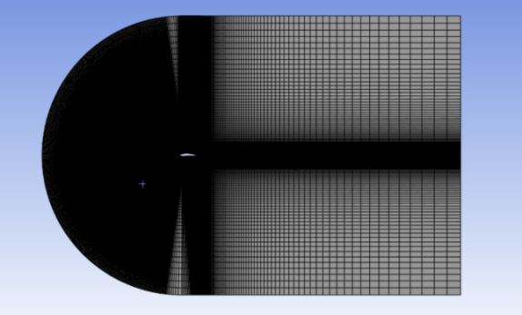
The website Airfoil Tools is used to generate the aerofoils’ geometry and the data of their shape, and, the data were then loaded into ANSYS SpaceClaim. The geometries of NACA 2415 and NACA 4415 are shown in Figure 1. C-type flow domain is used, which is divided into 6 sub-domains. In Figure 2, both the side length of the square and the diameter of the semicircle are 15 times the chord length.
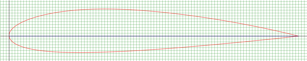
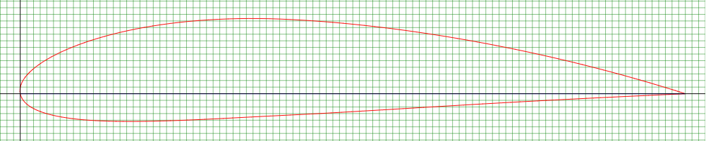
Figure 1: (a) Geometry of NACA 2415; (b) Geometry of NACA4415
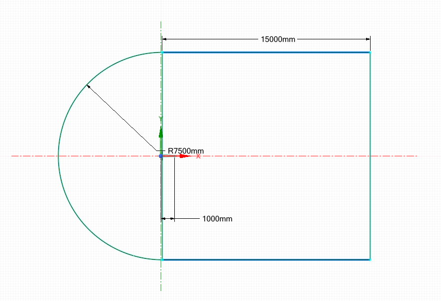
Figure 2: Flow domain
2.2. Grid generation
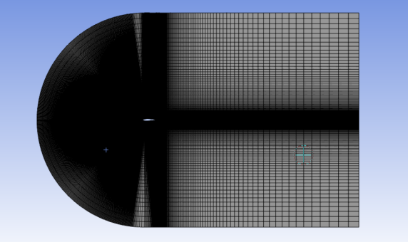
The inner zone of the flow domain has a greater impact on the results, so fine mesh is applied in this area to better simulate the state of airflow. Coarser mesh is used in the outer area since this area has less effect on the results of the calculation. A velocity inlet and pressure outlet are used for the boundary condition. It should be noted that the thickness of the first layer of the mesh should be smaller than the Y+ value to properly simulate the flow state in the boundary layer. The average orthogonal qualities of the two grids are 0.98378 and 0.98032 respectively. Figure 3 shows the mesh of each aerofoil.
(a)(b)
Figure 3: (a) Mesh of NACA2415; (b) Mesh of NACA4415
2.3. Computational conditions
SST k-omega viscous model is chosen, and the viscosity and density of the air are set to the default values. 500 iterations are performed so that the results can converge and the duration of the calculation can be minimized. And the limit for convergence is set to 1e-6. The website CFD Online is used again to calculate the Reynolds number at the 33 m/s airspeed. Table 1 shows the settings needed.
Table 1: Settings
Solver | Pressure-based |
Temperature [K] | 288.16 |
Type of Fluid | air |
Viscosity [kg/(ms)] | 1.7894e-05 |
Density [kg/m \( { ^{3}} \) ] | 1.225 |
Viscous Model | SST k-omega |
Time | steady |
Chord Length [m] | 1 |
Reynolds Number | 2300000 |
Speed of Air | 33 m/s |
Angle of Attack | 0-18° |
Number of Iterations | 500 |
Limit of Convergence | 1e-06 |
3. Results and discussion
ANSYS Fluent is used as the solver. The simulation results at various angles of attack (AOA) are compared and analysed.
3.1. The analysis of pressure and velocity contours
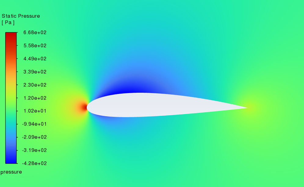
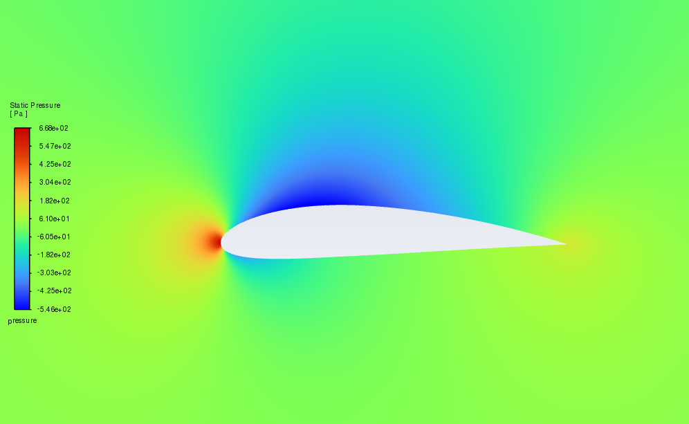
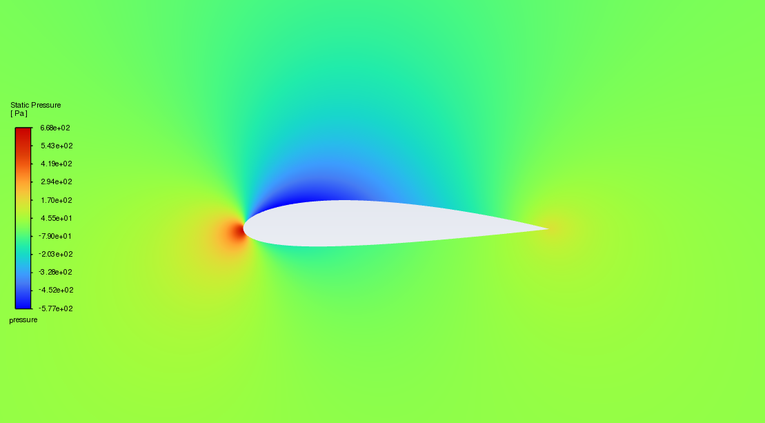
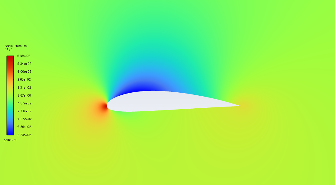
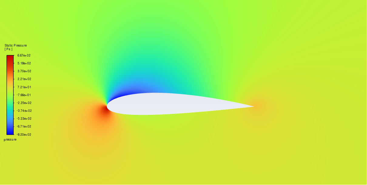
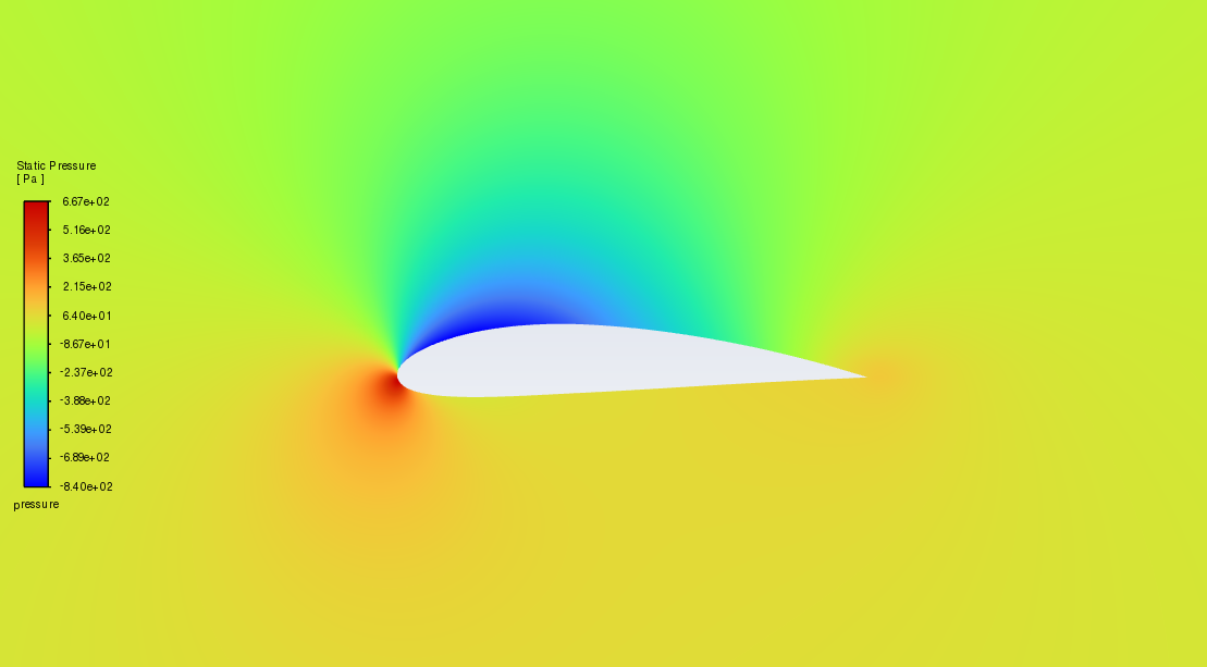
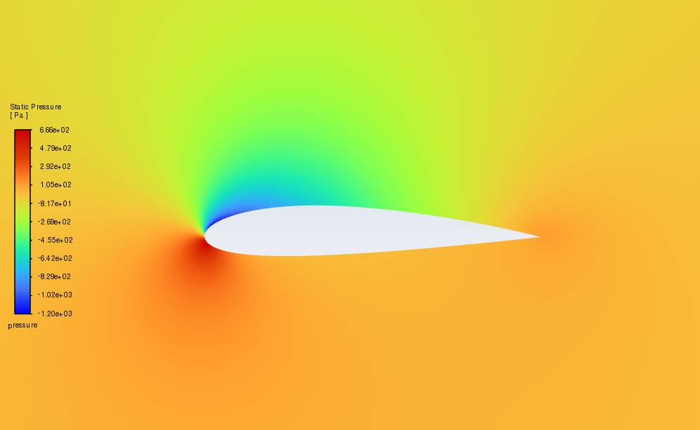
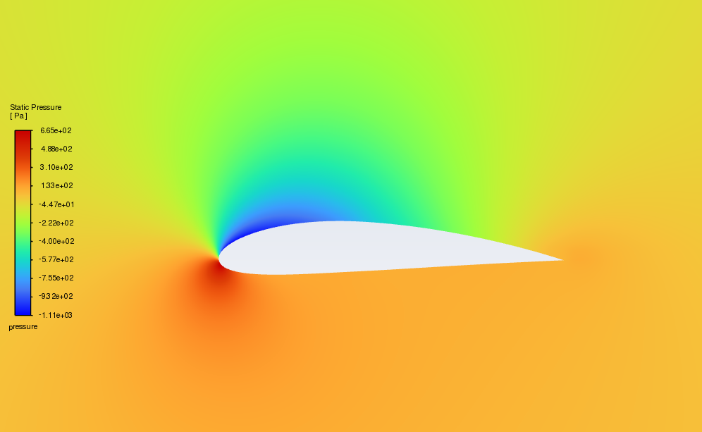
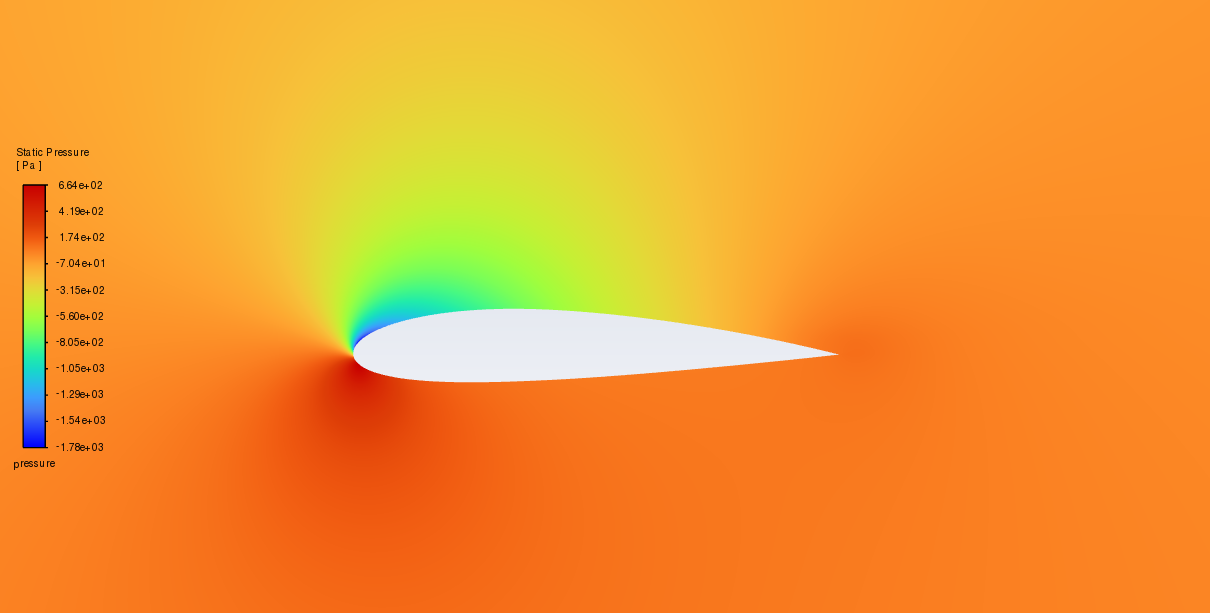
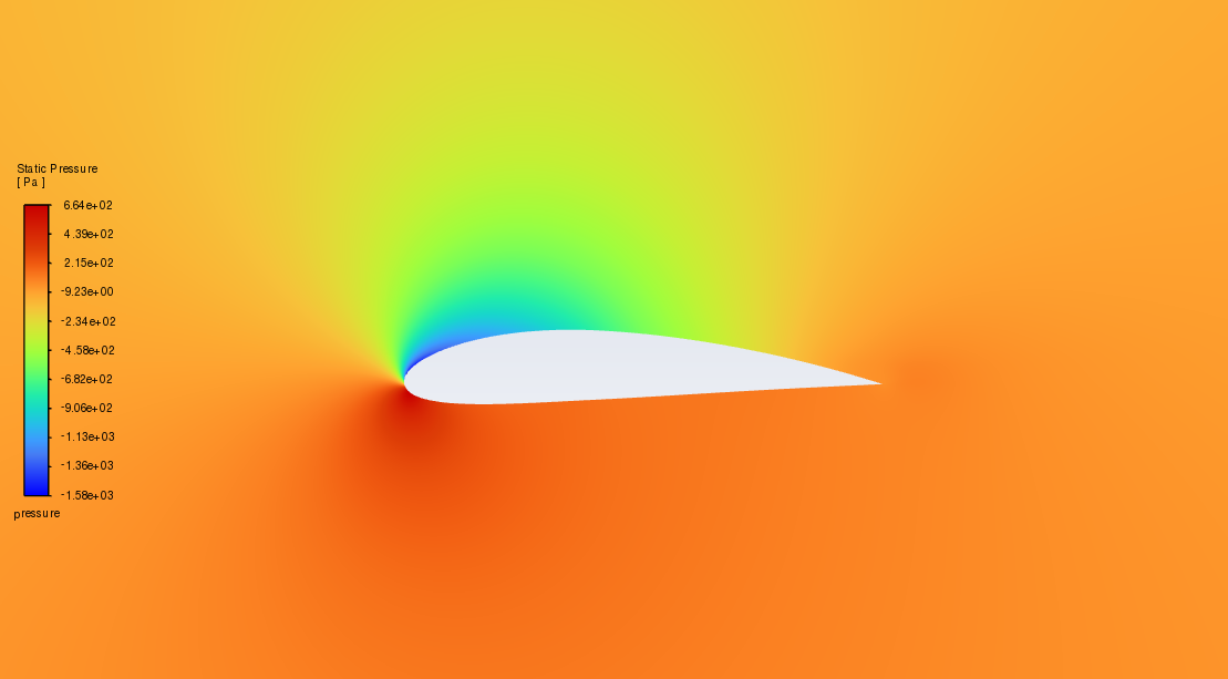
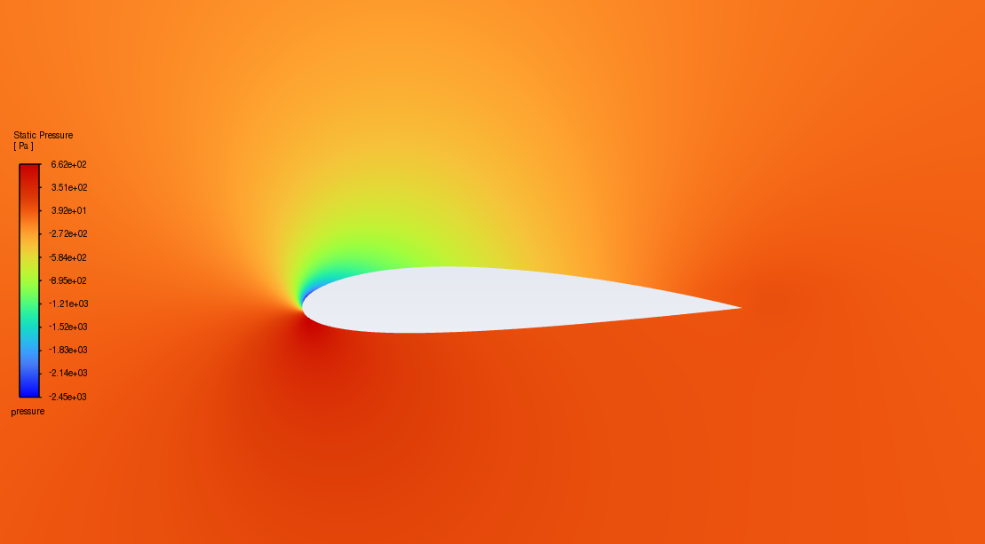
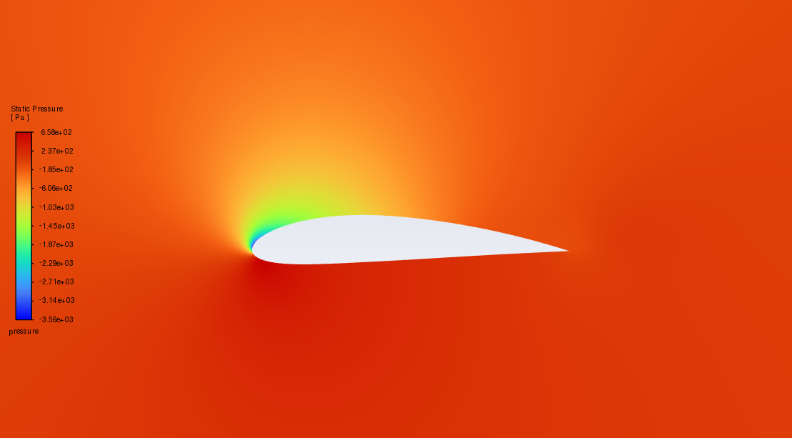
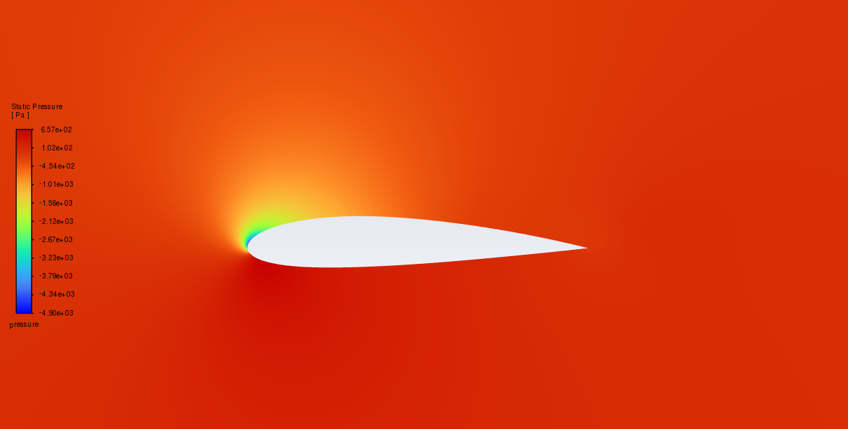
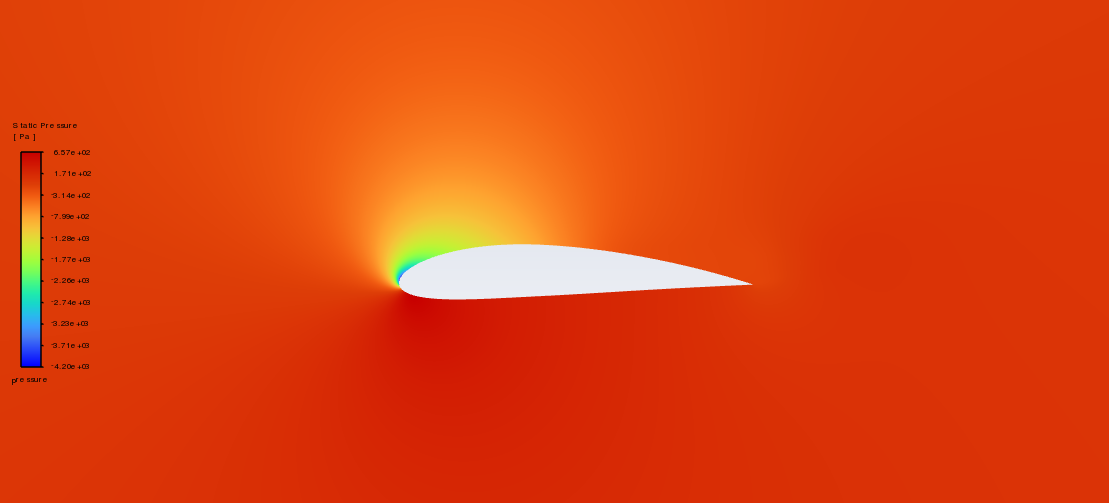
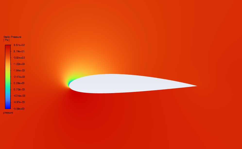
In, Figure 5 and Figure 6, the pressure and velocity distributions of NACA 2415 and NACA 4415 at 0-18° AOA are revealed.
NACA 2415NACA 4415


AOA=0°


AOA=2°


AOA=4°


AOA=6°


AOA=8°


AOA=10°


AOA=12°


AOA=14°


AOA=16°


AOA=18°
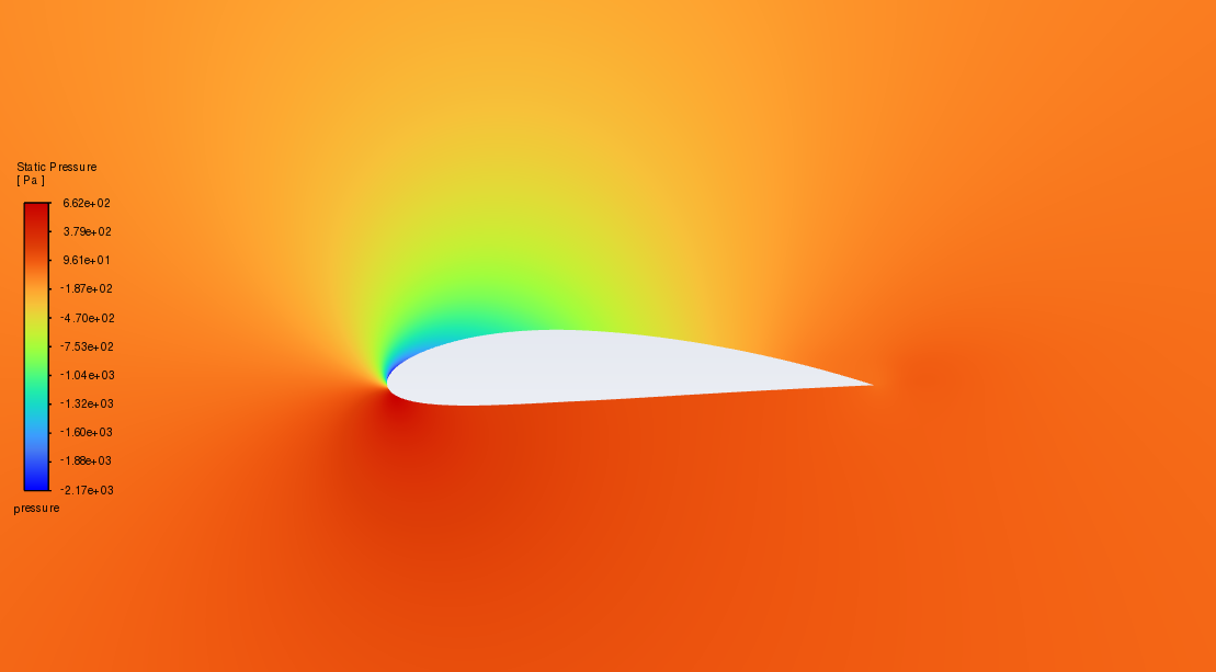
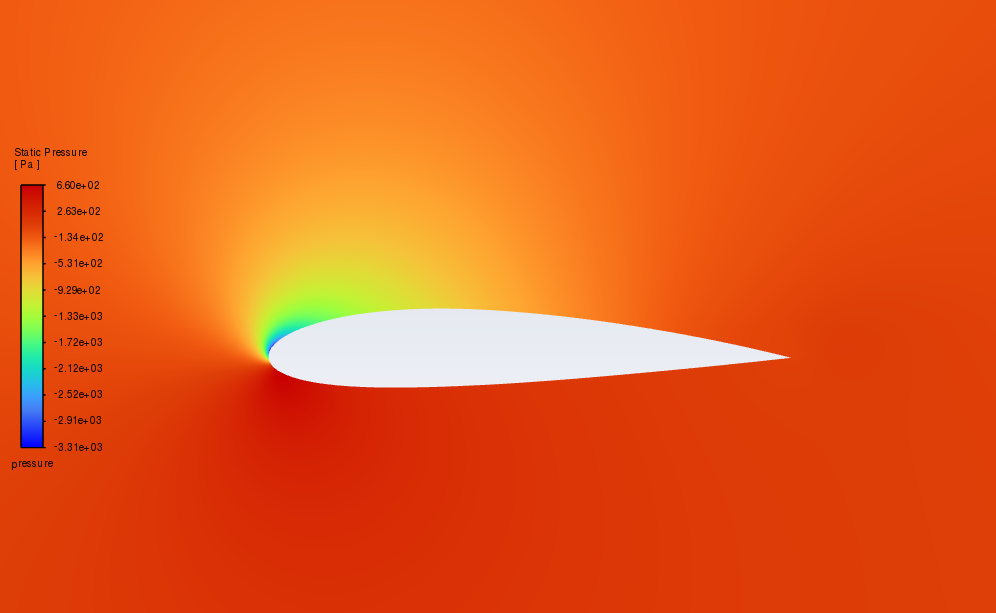
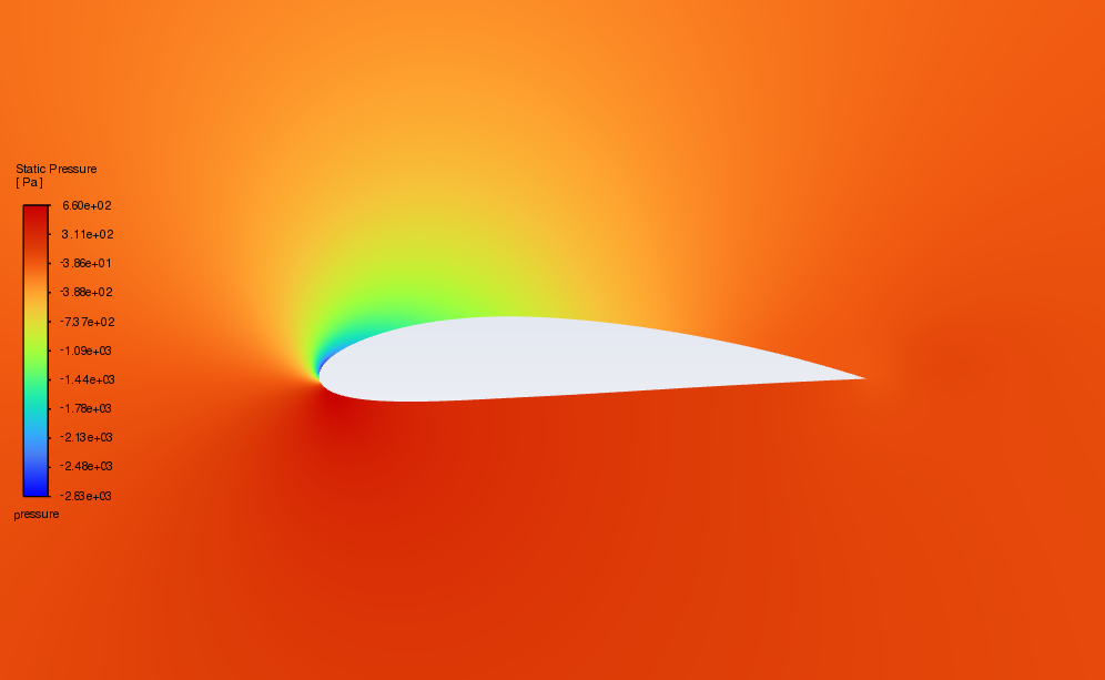
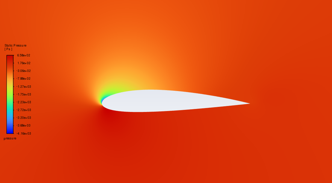
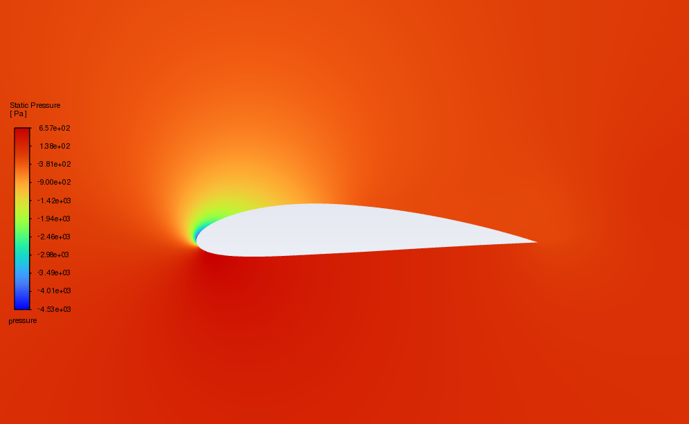
Figure 5: comparison of pressure contours of NACA 2415 and NACA 4415
NACA 2415 NACA 4415


AOA=0°


AOA=2°


AOA=4°


AOA=6°


AOA=8°


AOA=10°


AOA=12°


AOA=14°


AOA=16°


AOA=18°
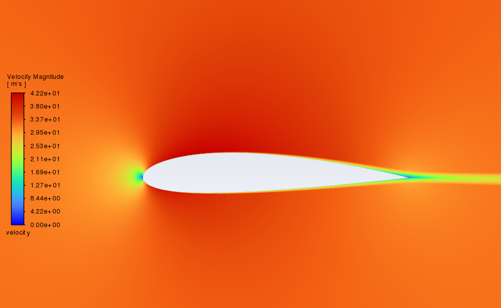
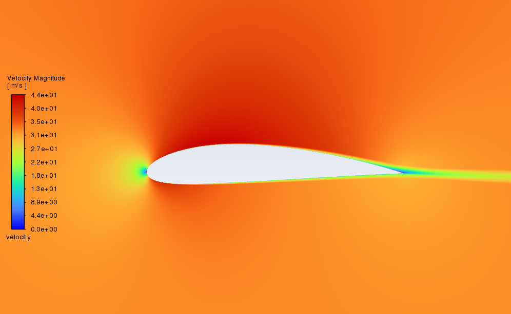
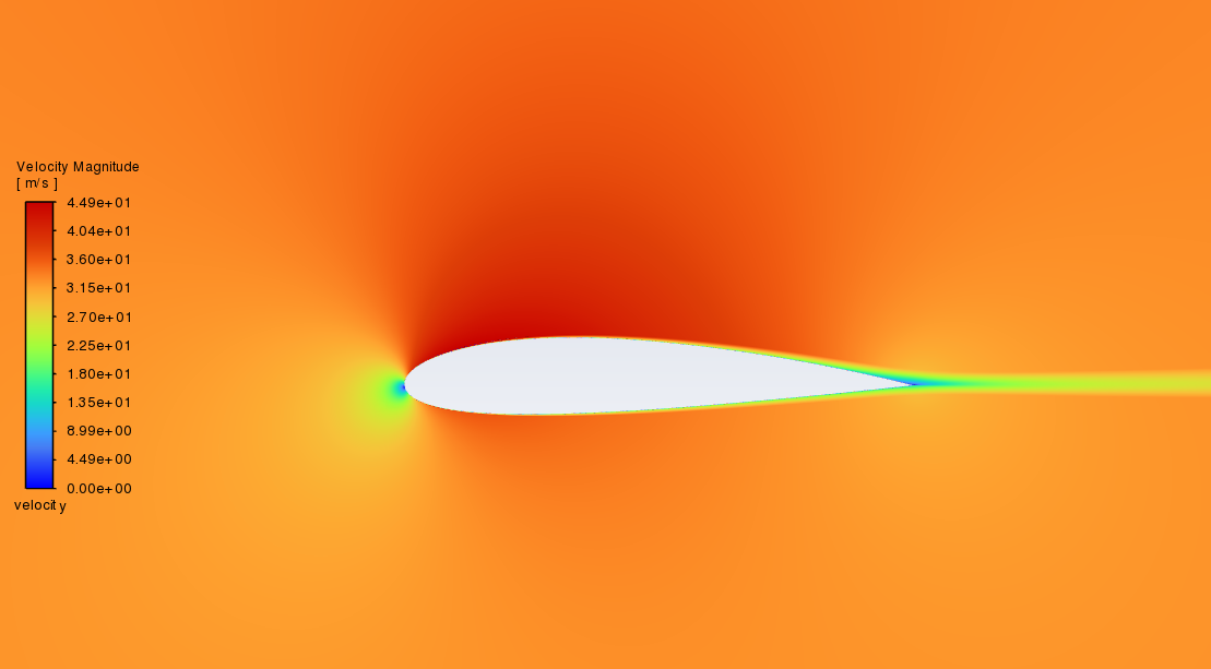
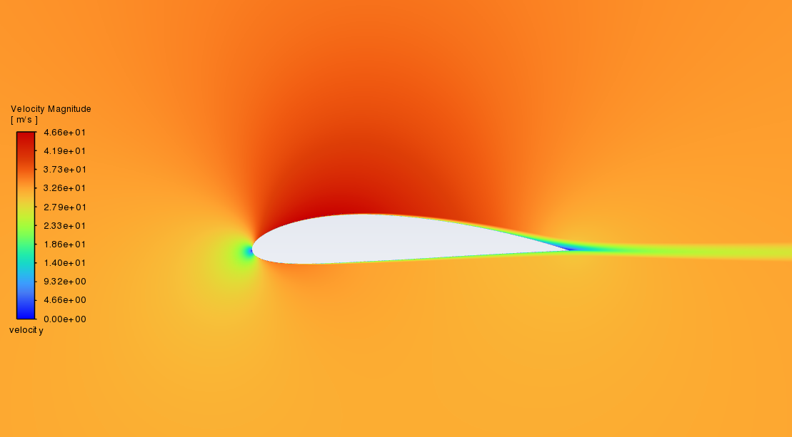
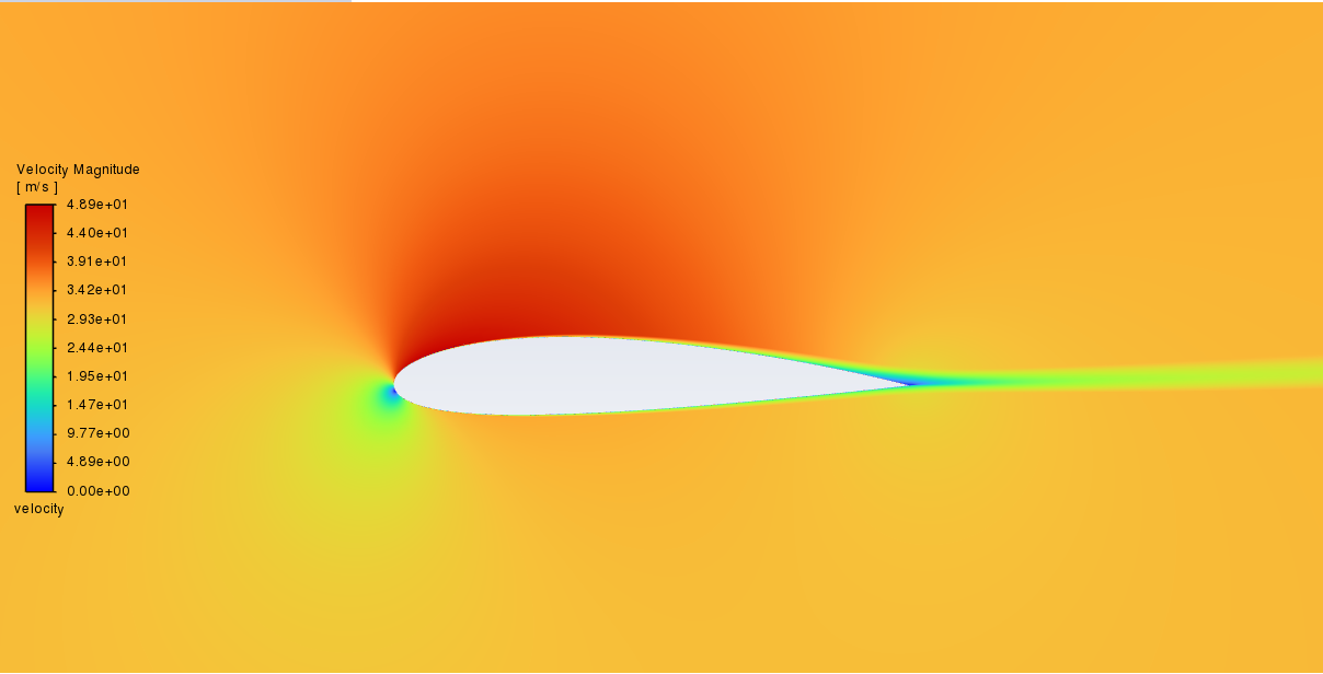
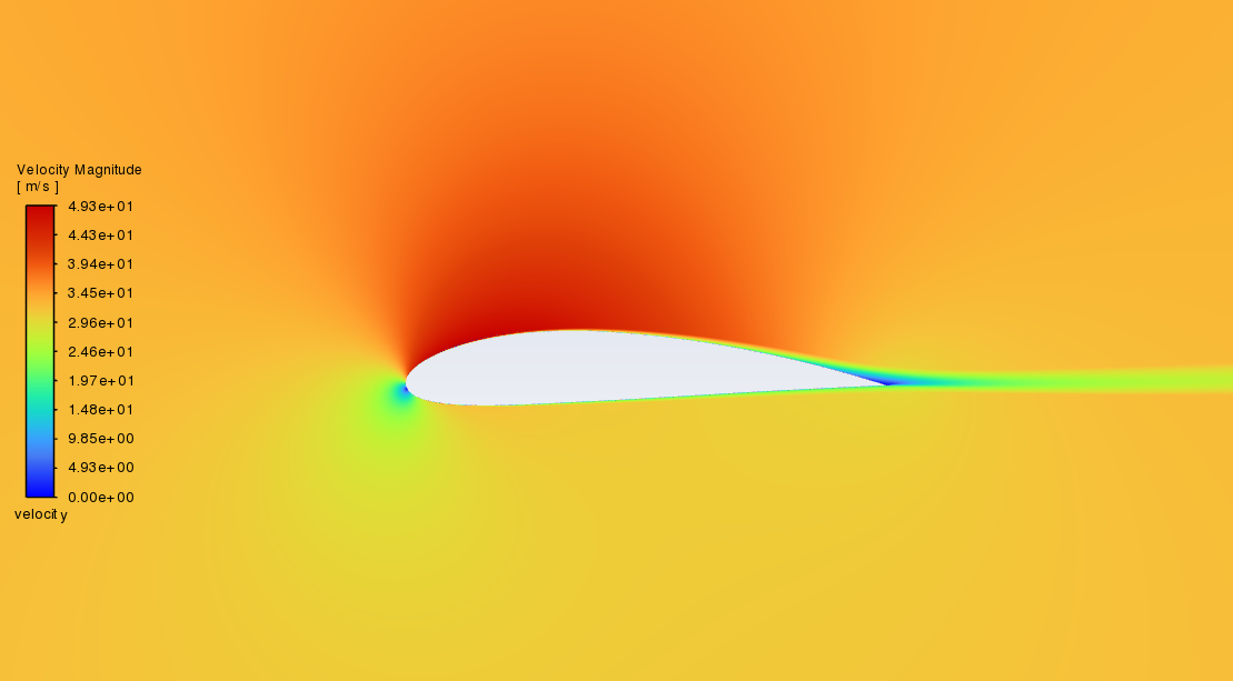
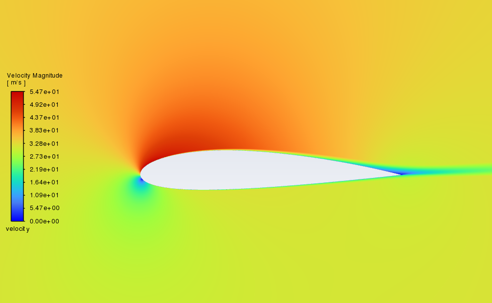
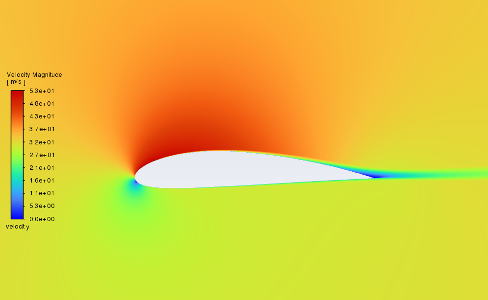
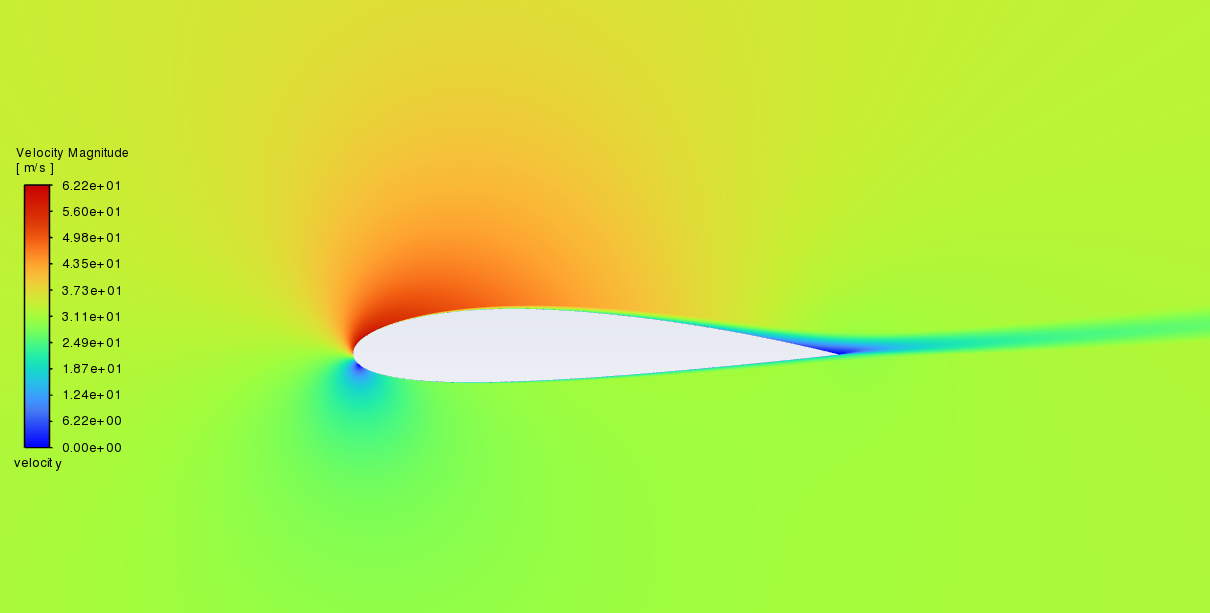
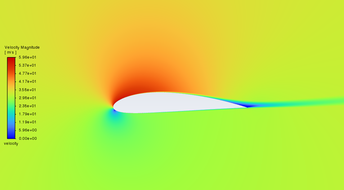
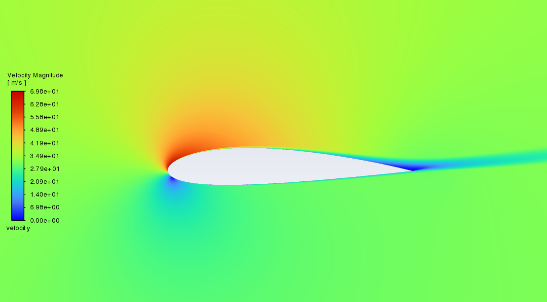
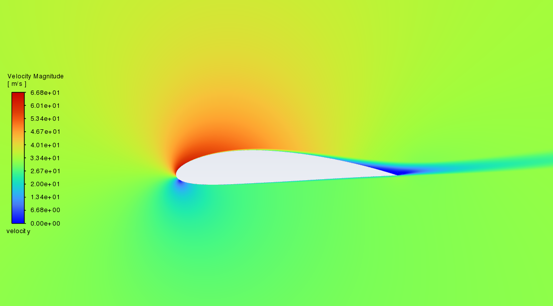
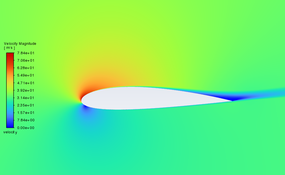
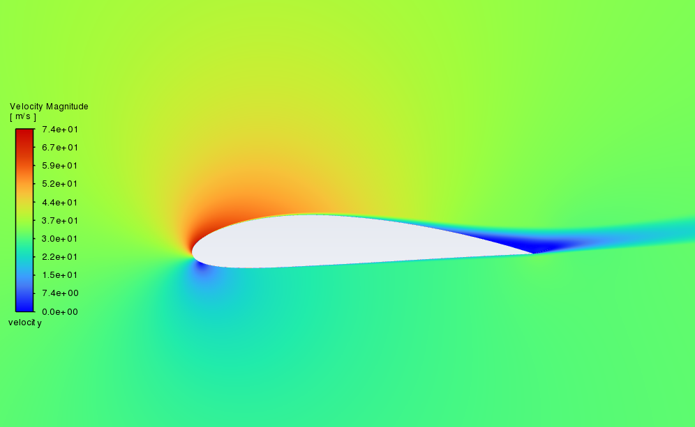
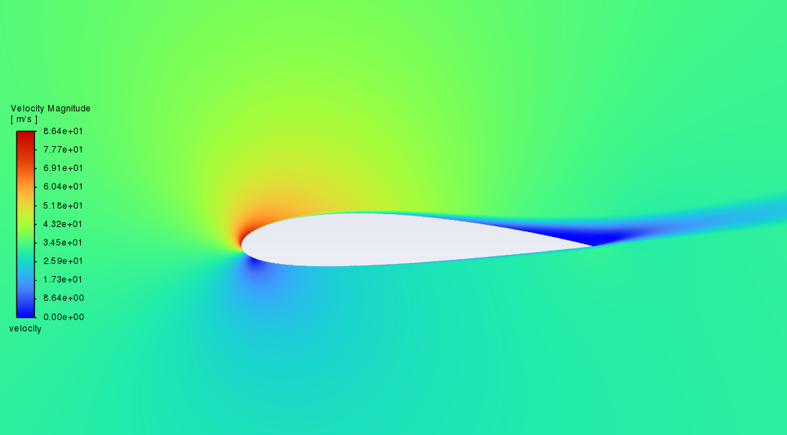
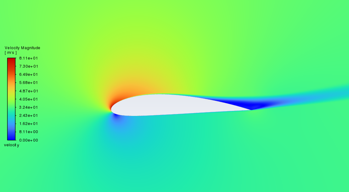
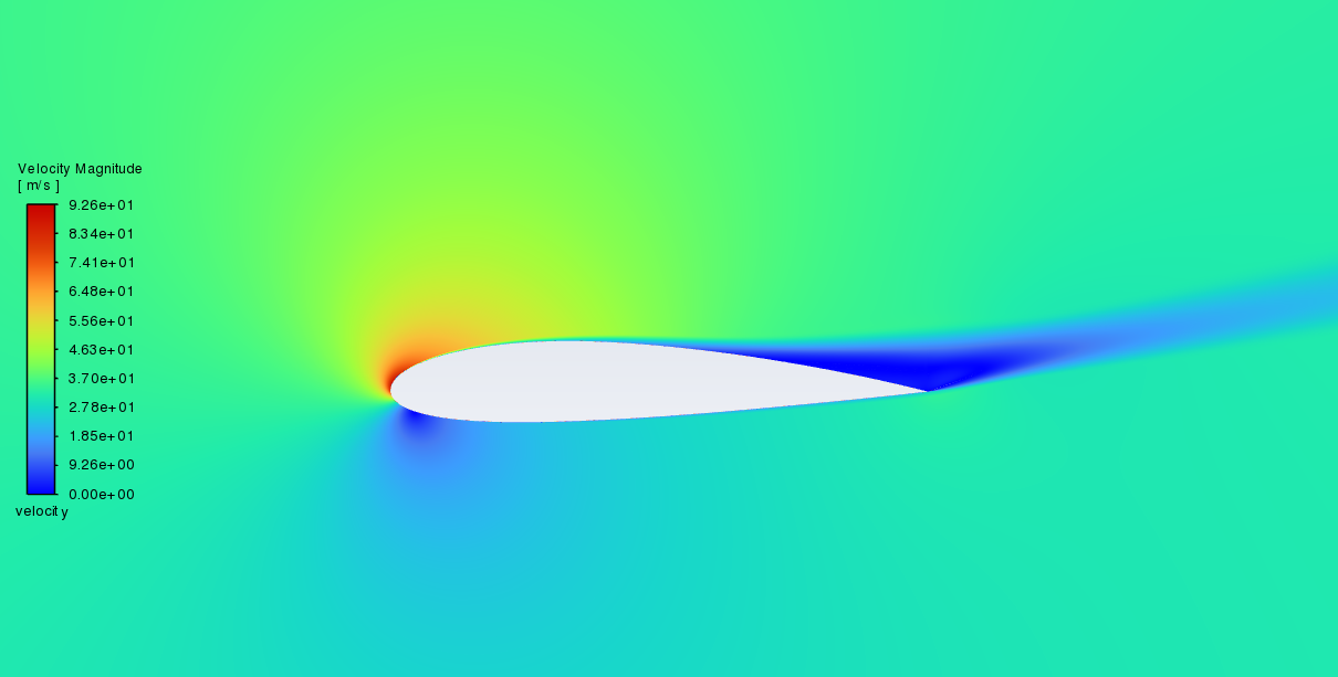
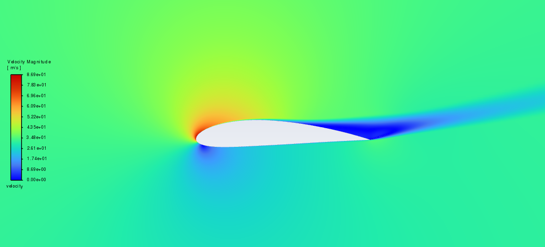
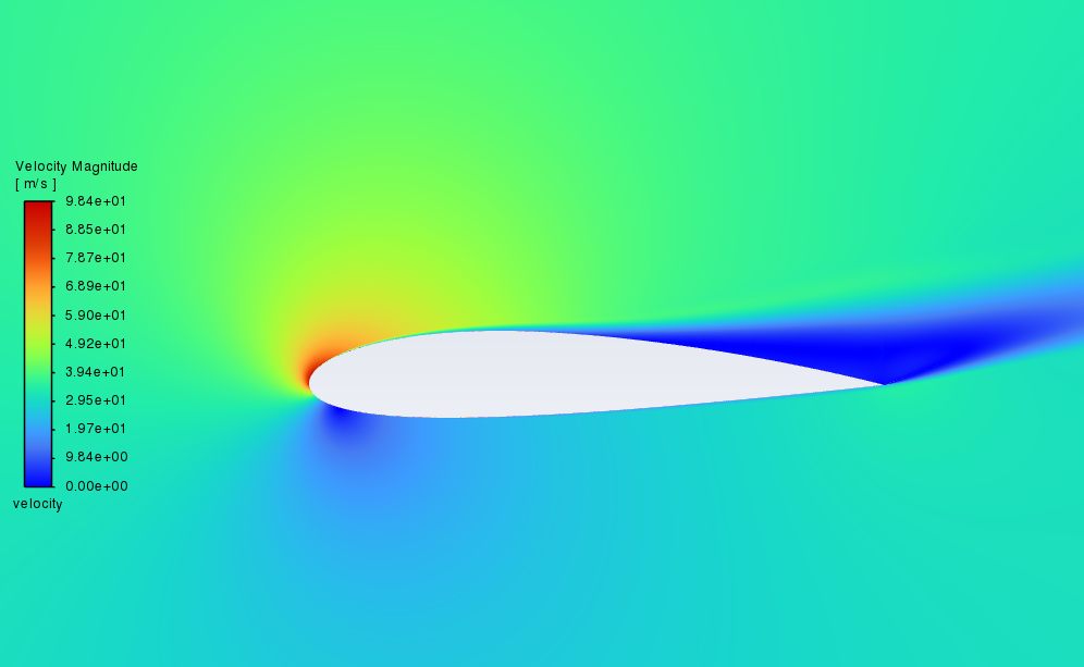
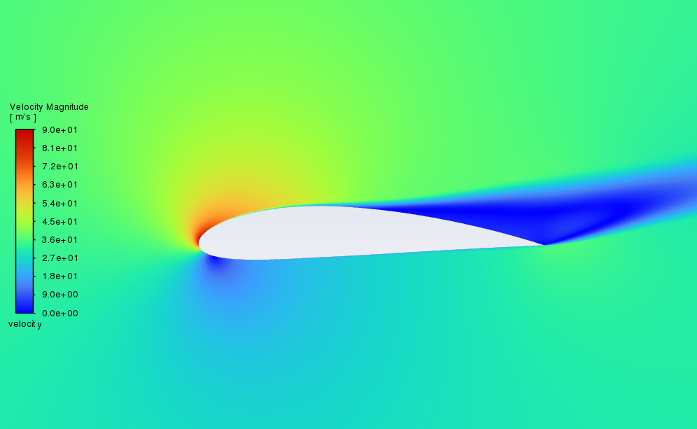
Figure 6: Comparison of velocity contours of NACA 2415 and NACA 4415
From the pressure contours in Figure 5, when AOA is in the range of 0-16°, a low-pressure area can be found close to the top surface, and the pressure on the top surface increases along the direction of the airstream. Correspondingly, a high-pressure zone can be found close to the bottom surface. According to the principle of lift, the pressure difference between top and bottom surfaces would generate an upward resultant force, i.e., lift, on the aerofoil, and that is how the aircraft stays in the air. As AOA increases, the above pattern of pressure distribution does not change. However, the pressure on the top surface becomes lower while the pressure on the bottom surface becomes higher, which indicates that the lift increases with AOA. Compared to NACA 2415, the low-pressure zone at the top surface of NACA 4415 is larger, and the pressure at the bottom surface is higher, at the same AOA. This indicates that in the range of 0-16° of AOA, NACA 4415 can provide a greater lift than NACA 2415.
From the velocity contours in Figure 6, a stagnation point can be found near each aerofoil’s leading edge. As AOA equals 0°, the stagnation point is directly in front of the leading edge. With the increase of AOA, the stagnation points of each aerofoil displace downwards and downstream, while the position occurring flow separation displaces forward. The velocity of the air at the top surface is much higher than that at the bottom surface, and the velocity on the top surface decreases as the air flows downstream. Compared to NACA 2415, the flow separation of NACA 4415 occurs earlier, and the wake region of NACA 4415 is wider, at the same AOA. This is because NACA 4415 is more cambered than NACA 2415. When AOA is equal to 18°, both aerofoils would stall due to the decrease of lift caused by the significant flow separation.
3.2. The comparison of Cl, Cd, and Cl/Cd between the two aerofoils
(a)(b)
(c)
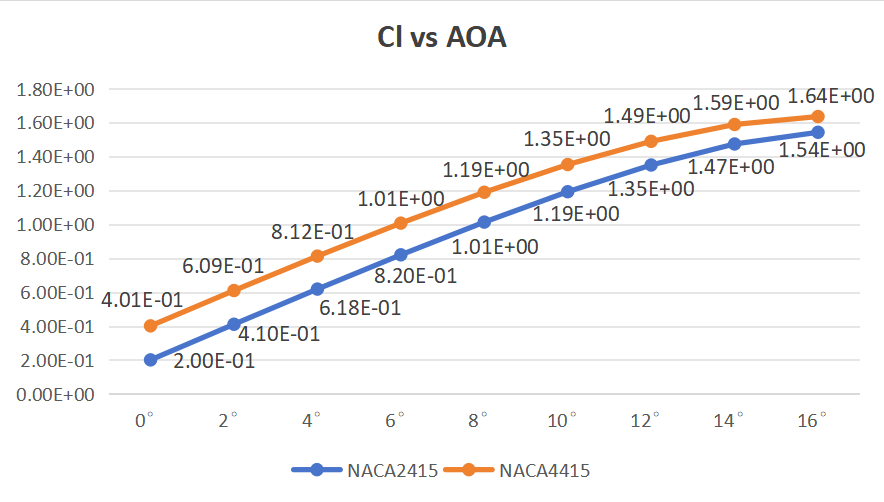
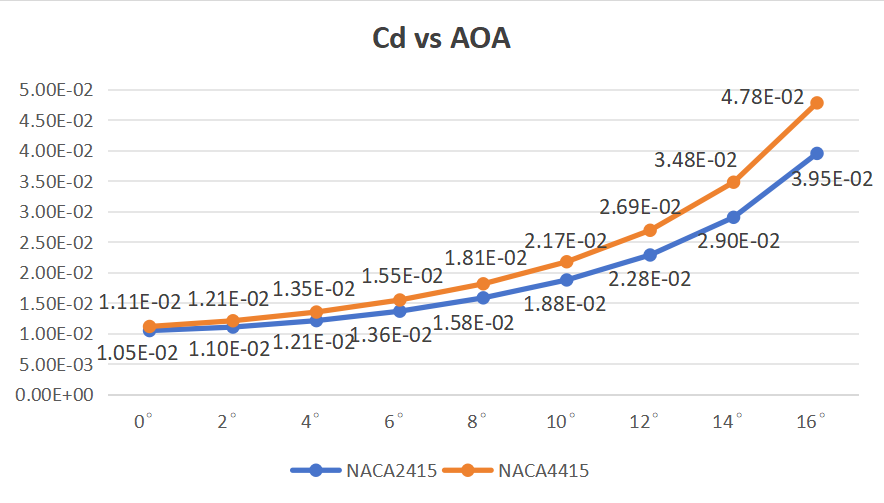
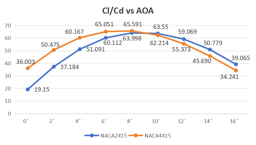
Figure 7: Comparison between (a) Cl, (b) Cd, and (c) Cl/Cd against the angle of attack for NACA 2415 and NACA 4415
Figure 7 shows the lift coefficient (Cl), drag coefficient (Cd), and lift-drag ratio (Cl/Cd) of NACA 2415 and NACA 4415 when AOA varies from 0 to 16°. As AOA increases, Both the Cl and Cd of the two aerofoils increase, while the lift-drag ratios initially rise to their maximums and then decline. Compared to the Cl of NACA 2415, it can be found that the Cl of NACA 4415 is always larger at the same AOA. When the AOA is above 10°, the difference between the Cl of the two aerofoils decreases significantly. The Cd of NACA 4415 is also always greater at the same AOA, compared to NACA 2415. Unlike the Cl, the difference between the Cd of the two aerofoils becomes increasingly larger while AOA increases. When AOA is in the range 0-9°, the magnitude of Cl/Cd of NACA 2415 is smaller than the value of NACA 4415. When AOA is in the range of 9-16°, NACA 2415 has a larger Cl/Cd value than NACA 4415.
4. Conclusions
Based on CFD software ANSYS Fluent, the two-dimensional aerodynamic characteristics of NACA 2415 and NACA 4415 had been analysed and compared. The website Aerofoil tools had been used to import the geometries of the two aerofoils, and ANSYS Mesh had been used for mesh generation. To minimize calculation time while ensuring convergence and accuracy of the results, biasing is applied so that a fine mesh can be generated for the inner part of the flow domain. Using the website CFD Online, the Y+ value was found to be larger than the thickness of the first layer of mesh, and the Reynolds number was calculated to be 2.3e6. Velocity inlet and pressure outlet had been chosen for boundary conditions. The calculation had been conducted with a pressure-based solver, and no heat transfer is considered to occur. The k-omega SST viscous model was chosen to simulate the state of the airstream. The number of iterations had been set to 500 to obtain convergent results in a relatively short time. Through calculation, the pressure contours, velocity contours, lift coefficients, and drag coefficients at different AOA were obtained, and all these results were analysed and compared. The results showed that the lift-drag ratio of NACA 4415 was higher at smaller AOA, while that of NACA 2415 was higher at larger AOA. The variation and differences in lift coefficients can be explained by the pressure contours. This research will offer data and a scientific basis for subsequent aerofoil studies and selections.
This research only discussed the aerodynamics of NACA 2415 and NACA 4415 at a high Reynolds number, and the range of AOA included was relatively small. In future studies, the range of AOA could be extended, so that the aerodynamic characteristics at negative AOA could be studied. Besides, the critical AOA could be determined as well. After that, a similar study could be conducted for a lower Reynolds number, in which the aerodynamic characteristics could be compared to this new condition.
References
[1]. Genç, M. S., Karasu, İ., & Açıkel, H. H. (2012). An experimental study on aerodynamics of NACA2415 aerofoil at low Re numbers. Experimental Thermal and Fluid Science, 39, 252-264. https://doi.org/10.1016/j.expthermflusci.2012.01.029
[2]. Kumar, V., Tomar, V., Kumar, N., & Jain, S. (2015). Flow Simulation and Theoretical Investigation on Aerodynamics of NACA-2415 Aerofoil at Low Reynolds Number (No. 2015-01-2576). SAE Technical Paper. https://doi.org/10.4271/2015-01-2576
[3]. Kharulaman, L., Aabid, A., Mehaboobali, F. A. G., & Khan, S. A. (2019). Research on flows for NACA 2412 Airfoil using computational fluid dynamics method. Int. J. Eng. Adv. Technol, 9(1), 5450-5456. 10.35940/ijeat. A3085.109119
[4]. Mukhti, M. A. Q. A., Didane, D. H., Ogab, M., & Manshoor, B. (2021). Computational fluid dynamic simulation study on NACA 4412 airfoil with various angles of attacks. Journal of Design for Sustainable and Environment, 3(1).
[5]. Hasan, S. M., Islam, S. M., & Haque, M. Comparison of Aerodynamic Characteristics of NACA 0012 and NACA 2412 Airfoil. https://doi.org/10.22214/ijraset.2021.36766
[6]. Rubel, R. I., Uddin, M. K., Islam, M. Z., & Rokunuzzaman, M. (2016). Comparison of Aerodynamics Characteristics of NACA 0015 & NACA 4415. https://doi.org/10.20944/preprints201610.0095.v1
[7]. Pane, M. (2023). Wing Simulation Using Naca 2412 and 2415 Airfoils with Variations in Angle of Attack for Lift and Drag. VANOS Journal of Mechanical Engineering Education, 8(2), 190-199. https://dx.doi.org/10.30870/vanos.v8i2.22321
[8]. Kulshreshtha, A., Gupta, S. K., & Singhal, P. (2020). FEM/CFD analysis of wings at different angle of attack. Materials Today: Proceedings, 26, 1638-1643. https://doi.org/10.1016/j.matpr.2020.02.342
Cite this article
Zhuang,Y. (2025). Comparison of Aerodynamic Characteristics of NACA 2415 and NACA 4415 Aerofoils. Applied and Computational Engineering,130,58-67.
Data availability
The datasets used and/or analyzed during the current study will be available from the authors upon reasonable request.
Disclaimer/Publisher's Note
The statements, opinions and data contained in all publications are solely those of the individual author(s) and contributor(s) and not of EWA Publishing and/or the editor(s). EWA Publishing and/or the editor(s) disclaim responsibility for any injury to people or property resulting from any ideas, methods, instructions or products referred to in the content.
About volume
Volume title: Proceedings of the 5th International Conference on Materials Chemistry and Environmental Engineering
© 2024 by the author(s). Licensee EWA Publishing, Oxford, UK. This article is an open access article distributed under the terms and
conditions of the Creative Commons Attribution (CC BY) license. Authors who
publish this series agree to the following terms:
1. Authors retain copyright and grant the series right of first publication with the work simultaneously licensed under a Creative Commons
Attribution License that allows others to share the work with an acknowledgment of the work's authorship and initial publication in this
series.
2. Authors are able to enter into separate, additional contractual arrangements for the non-exclusive distribution of the series's published
version of the work (e.g., post it to an institutional repository or publish it in a book), with an acknowledgment of its initial
publication in this series.
3. Authors are permitted and encouraged to post their work online (e.g., in institutional repositories or on their website) prior to and
during the submission process, as it can lead to productive exchanges, as well as earlier and greater citation of published work (See
Open access policy for details).
References
[1]. Genç, M. S., Karasu, İ., & Açıkel, H. H. (2012). An experimental study on aerodynamics of NACA2415 aerofoil at low Re numbers. Experimental Thermal and Fluid Science, 39, 252-264. https://doi.org/10.1016/j.expthermflusci.2012.01.029
[2]. Kumar, V., Tomar, V., Kumar, N., & Jain, S. (2015). Flow Simulation and Theoretical Investigation on Aerodynamics of NACA-2415 Aerofoil at Low Reynolds Number (No. 2015-01-2576). SAE Technical Paper. https://doi.org/10.4271/2015-01-2576
[3]. Kharulaman, L., Aabid, A., Mehaboobali, F. A. G., & Khan, S. A. (2019). Research on flows for NACA 2412 Airfoil using computational fluid dynamics method. Int. J. Eng. Adv. Technol, 9(1), 5450-5456. 10.35940/ijeat. A3085.109119
[4]. Mukhti, M. A. Q. A., Didane, D. H., Ogab, M., & Manshoor, B. (2021). Computational fluid dynamic simulation study on NACA 4412 airfoil with various angles of attacks. Journal of Design for Sustainable and Environment, 3(1).
[5]. Hasan, S. M., Islam, S. M., & Haque, M. Comparison of Aerodynamic Characteristics of NACA 0012 and NACA 2412 Airfoil. https://doi.org/10.22214/ijraset.2021.36766
[6]. Rubel, R. I., Uddin, M. K., Islam, M. Z., & Rokunuzzaman, M. (2016). Comparison of Aerodynamics Characteristics of NACA 0015 & NACA 4415. https://doi.org/10.20944/preprints201610.0095.v1
[7]. Pane, M. (2023). Wing Simulation Using Naca 2412 and 2415 Airfoils with Variations in Angle of Attack for Lift and Drag. VANOS Journal of Mechanical Engineering Education, 8(2), 190-199. https://dx.doi.org/10.30870/vanos.v8i2.22321
[8]. Kulshreshtha, A., Gupta, S. K., & Singhal, P. (2020). FEM/CFD analysis of wings at different angle of attack. Materials Today: Proceedings, 26, 1638-1643. https://doi.org/10.1016/j.matpr.2020.02.342