


1. Introduction
Aerofoil is the main component of the aviation system, which is defined as a two-dimensional cross-section of aircraft wings, and its influence on aviation spacecraft is important [1]. The design and construction of aerofoil greatly affect the resistance, lift, performance in different situations and the efficiency of fuel. Because of that, the optimization and selection of aerofoils are of great importance in aviation. Aerofoil can be segmented into symmetric aerofoil and asymmetric aerofoil according to the symmetry of the upper and lower surfaces, among which the asymmetric wing is extensively used in supersonic vehicles and other fields.
NACA aerofoil is a series of classic aerofoil proposed by the National Aviation Advisory Council in the middle of the 20th. Their designs have been widely recognized and highly appreciated in the aviation field [2]. The aerofoils were divided into 4 position aerofoil family, 5-position aerofoil family, 6 position aerofoil family by maximum relative curvature of the aerofoil, relative position and so on. Among the large number of 4-bit and 5-bit aerofoil groups, NACA2412 and NACA25112 are widely studied and used because of their good aerodynamic characteristic. Therefore, these two aerofoils will be chosen to study for aerodynamic characteristics and visualize the results.
Studies about the aerodynamic performance of the two aerofoils can be conducted by numerical simulations. In addition to the different geometric structures, the comprehensive consideration of the aerodynamic performance is also a key factor in showing the performance of different aerofoil. Aerodynamic characteristics include lift coefficient, drag coefficient and stall characteristics, which will significantly affect the performance of aircraft in flight. Through the numerical simulation and experiment the performance. Specific situations can be studied more deeply, providing Reliable experimental data and the basis for subsequent studies and optimization. With the development of technology, Computational fluid mechanics have been used in the analysis of wing-type aerodynamic characteristics, providing significant help for aerofoil performance optimization [4]. However, because of the limitation of computer performance and other causes, there are also some problems with the actual situation. By modifying the layers of the model, the calculation results can be consistent with the expectations, and provide the scientific basis and reference for the subsequent wind tunnel testing.
This paper systematically compares the aerodynamic characteristics of NACA2412 and NACA25112 based on ANSYS Fluent fluid simulation software, and quantitatively analyses the velocity counter, pressure counter and lift resistance relationship at different attack angles. By comparing the performance differences between 4-bit and 5-bit aerofoil through concrete data systems, it provides guidance for the research and design of cross-family aircraft, and can also provide reference for subsequent research or the development of new aerofoil.
2. Computational Method
2.1. Geometric model and computational domain
The present study selected NACA2412 and NACA25112 as the research objects. The aerofoils geometry coordinates were imported into Fluent and continuity was set, resulting in continuous geometric curves for subsequent CFD simulations. The geometric curves of NACA2412 and NACA25112 are shown in Figure 1. Figure 2 illustrates the computational domain used for simulation. The entrance and exit sections are defined with velocity at the inlet and pressure at the outlet.
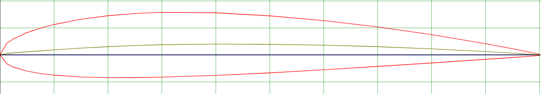
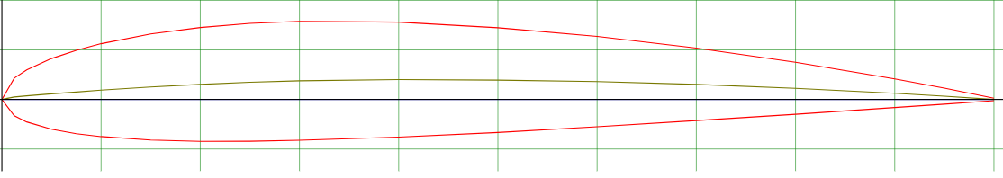
Figure 1: NACA2412 and NACA25112 geometric model
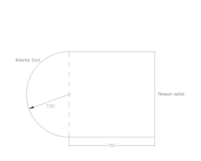
Figure 2: Computational domain
2.2. Grid division
Based on the Fluent geometric curves, meshing is performed by Ansys software in this article. A C-meshed domain is used for simulation in this experiment, with the velocity inlet composed of a semi-circle with a diameter 15 times the chord length. Adjacent boundaries and the pressure outlet are also 15 times the chord length. To accurately set up the flow field conditions, the flow domain is divided into six sub-domains. After smoothing treatment on the mesh, fine meshing around the aerofoil is achieved by setting bias styles and factors. It can better approximate real fluid flow conditions and simplify calculations for other parts of the mesh all at once. Thus improving computational speed and approaching more closely with actual situations. The mesh division of the flow field domain is shown in Figure 3, and detailed meshing around the aerofoil is shown in Figure 4.
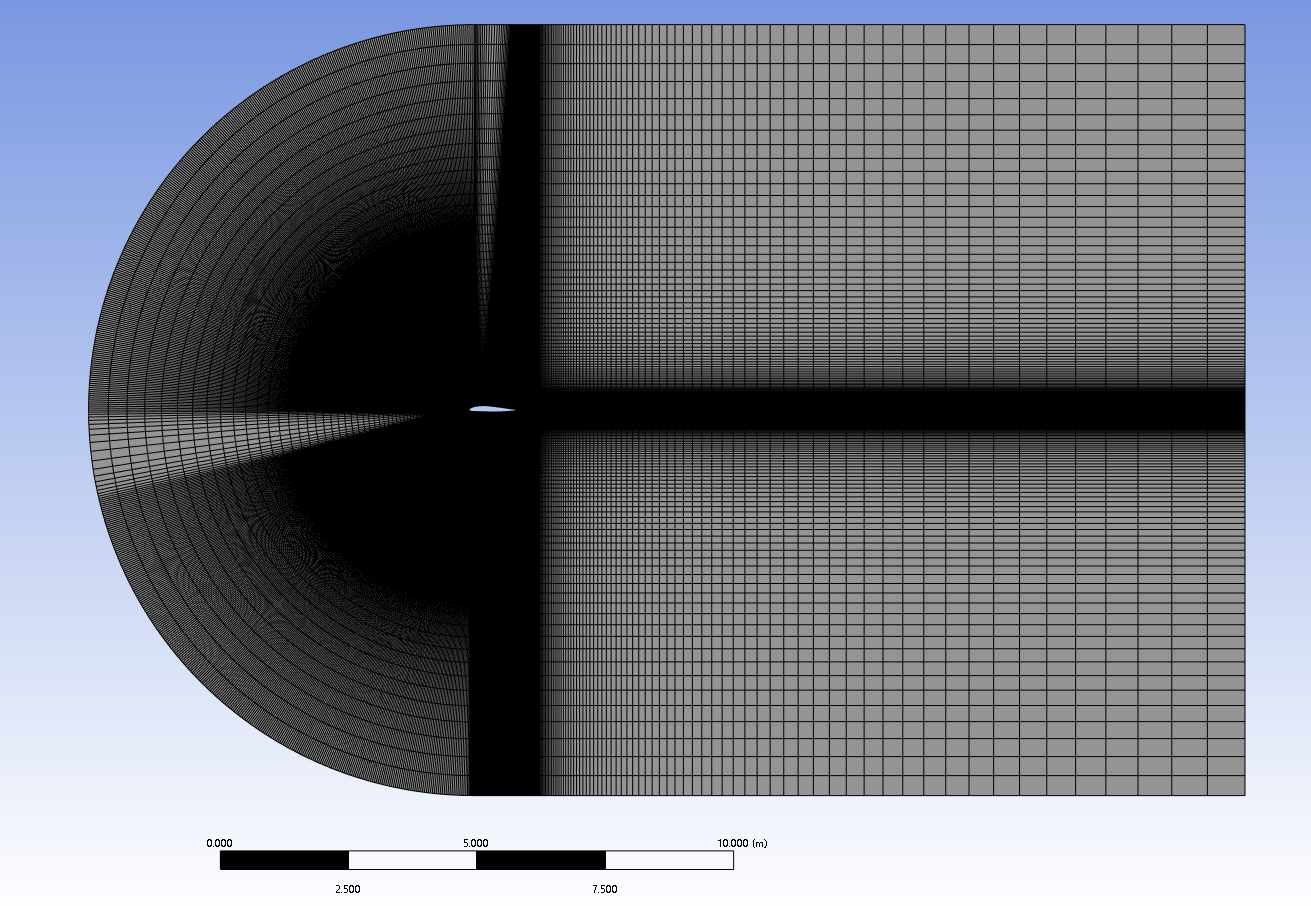
Figure 3: Flow domain
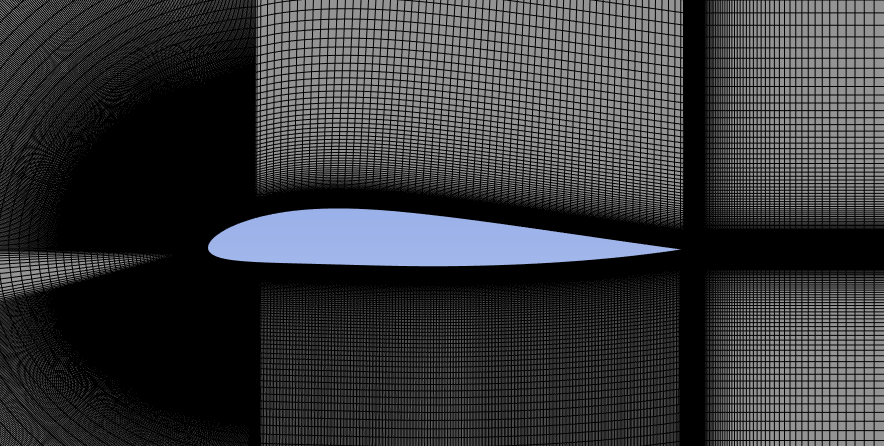
Figure 4: Detailed diagram of the aerofoil mesh
2.3. Boundary conditions and the government Eq
The boundary conditions refer to the physical properties or conditions on the surface of the region, representing specific flow variables of the physical model. To be consistent with subsequent test models, both aerofoil models have a chord length of 1m. The K-Omega model is chosen for numerical simulation to better simulate the aerodynamic characteristics of low Reynolds number aerofoils [5]. Meanwhile, 1000 iterations and a residual value of 10-6 are set to ensure convergence of results in the Anasys solver. The detailed parameters of boundary conditions for simulation calculation can be found in Table 1. The fundamental governing equations employed in this study are the incompressible continuity equation and the Navier-Stokes equations. [3]. The expression for the continuity equation is as follows:
\( \frac{∂ρ}{∂t}+∇\cdot (ρ\vec{V})=0 \) (1)
The Navier-Strokes equation expression is as follows:
\( \frac{∂}{∂t}(ρ\vec{V})+∇\cdot (ρ\vec{V}\vec{V})=-∇p+∇\cdot (\bar{\bar{r}})+ρ\vec{g}+\vec{F} \) (2)
Table 1: The boundary conditions
Solver | Pressure solver |
Model | K-Omega(2eqn) |
Fluid density | 1. 225Kg/m3 |
Inlet velocity | 30m/s |
Pressure | 1 ATM |
Reynolds number | 2e6 |
Chord length | 1m |
Initialization method | Hybrid Initialization |
3. Results and Discussion
In the study, detailed solutions about the NACA 2412 and NACA 25112 aerofoils based on the Fluent software to examine the pressure distribution and velocity distribution across the surface of aerofoils at various attack angles, including their aerodynamic properties like the relationships between lift and drag.
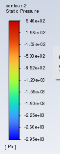
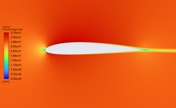
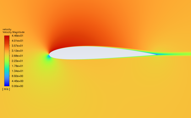
3.1. Pressure contour at different angles of attack
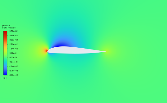
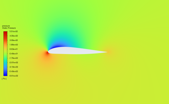
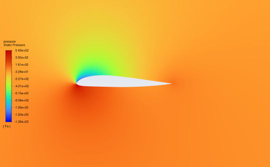
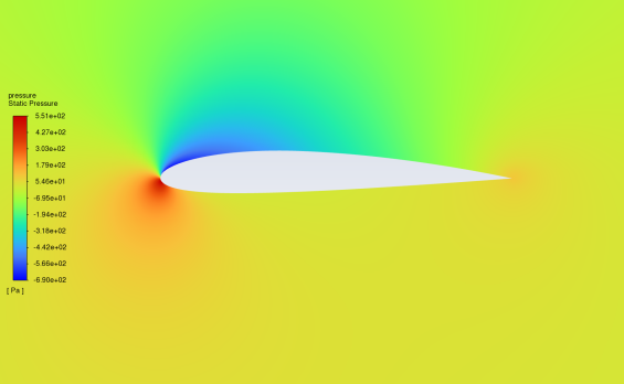
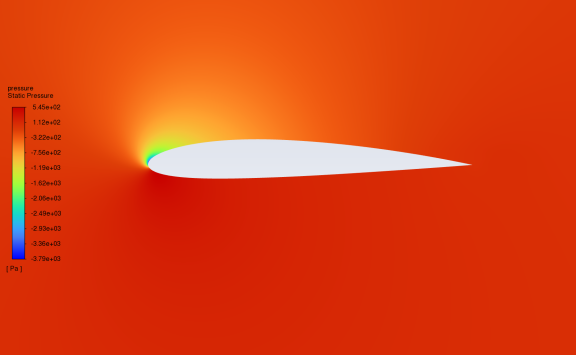
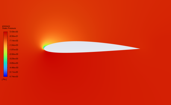
Figure 5 shows the contour of the static pressure comparing NACA2412 and NACA25112 in the 0°-16°attack range. The pressure contour denotes the pattern of pressure across the aerofoil’s surface, which can intuitively see the size of the pressure value of each part. From the figure, at the 0° attack, the highest static pressure point is at the leading edge. With increasing the attack angle, the pressure centre within the low-pressure zone on the upper surface progressively shifts towards the leading edge. At the 16 angles of attack, the Low-pressure region reaches the minimum value in the study range. Meanwhile, the high-pressure area gradually moves down, progressing from the vicinity of the leading edge towards the lower surface and eventually spanning the aerofoil. The above phenomena are reflected in both NACA2412 and NACA25112. When the pressure on the upper side of the aerofoil is lower than that on the underside, a lifting force is generated by the air.
(a)The pressure distribution at 0° attack (b) the pressure distribution at 4° attack
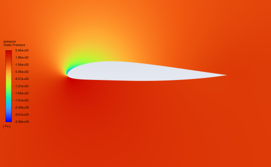
(c)the pressure distribution at 8° attack (d) the pressure distribution at 12° attack
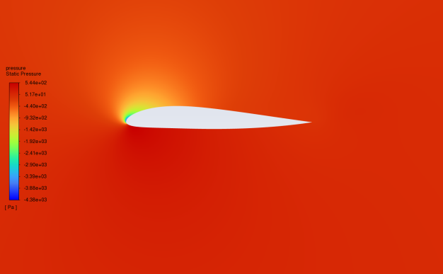
(e) the pressure distribution at 16° attack

(f) Pressure Index
Figure 5: Pressure contour of NACA25112 in 0°-16°attack angle
The pressure distribution at 0° attack (b) the pressure distribution at 4° attack 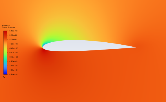
(c) the pressure distribution at 8° attack (d) the pressure distribution at 12° attack
(e) the pressure distribution at 16° attack
(f) Pressure Index
Figure 6: Pressure contour of NACA2412 in 0°-16°attack angle
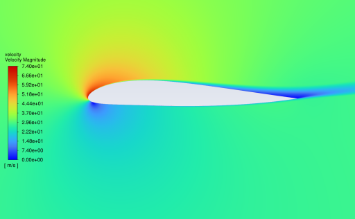
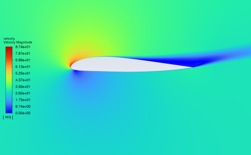
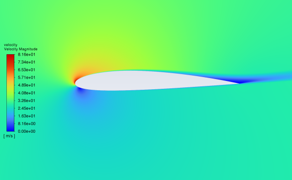
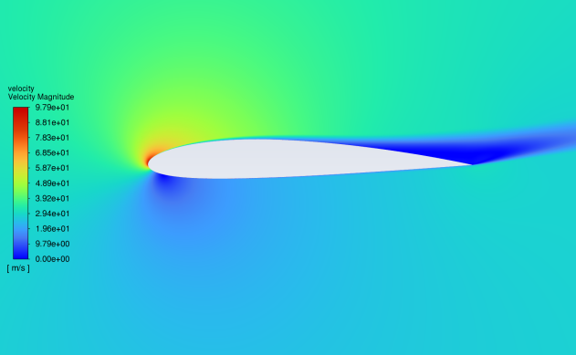
3.2. Velocity contour at different angles of attack
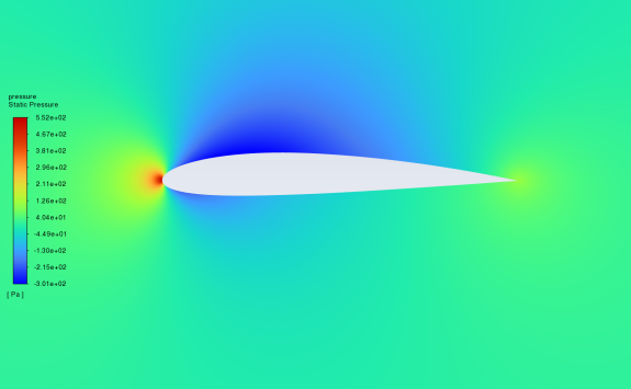
Figures 7 and 8 show the velocity contour of NACA25112 and NACA2412 fluid velocity at the 0-16 angles of attack. The velocity reference indicators are given on the left of the figure. The following characteristics are derived from the figure analysis: The lowest fluid velocity value appears at the leading-edge point of the aerofoil at the 0 angle of attack. At this time, the upper and lower surface fluid velocity is at a large value. The wake velocity is in the index median. With the gradual increase of the Angle of attack, the high-speed area is mainly distributed on the upper surface and gradually narrowed, the low-speed area gradually moves down, and the wake velocity also decreases; At the same time, at the small Angle of attack, the airflow through the upper and lower surface will smoothly meet at the rear edge to form a stationary point; As the angle of attack increases, the flow through the upper surface gradually becomes smoother, causing the separation point to move from the trailing edge to the leading edge[6]; The above phenomena appear in the fluid velocity simulation experiments of NACA25112 and NACA2412.
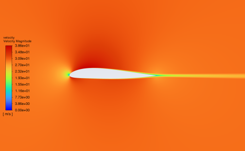
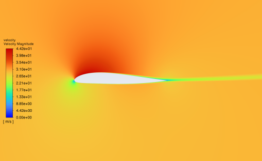
The velocity distribution at 0° attack (b) the velocity distribution at 4°attack
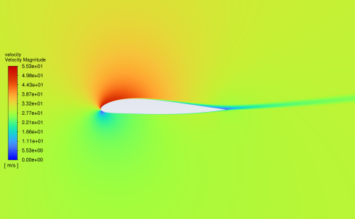
(c) the velocity distribution at 8° attack (d) the velocity distribution at 12° attack
(e) the velocity distribution at 16° attack

(f)Velocity index
Figure 7: Velocity contour of NACA25112 in 0°-16°attack angle
(a) The velocity distribution at 0° attack (b) the velocity distribution at 4°attack 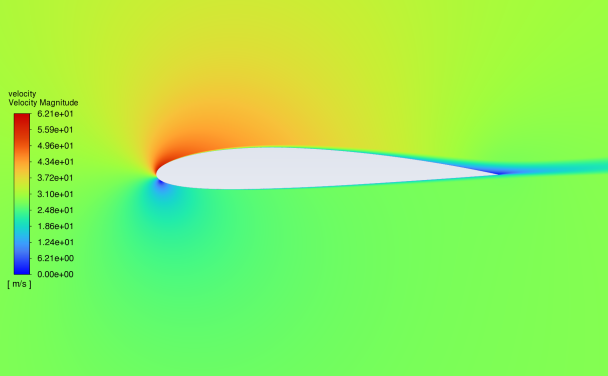
(c)the velocity distribution at 8° attack (d) the velocity distribution at 12° attack
(e) the velocity distribution at 16° attack
(f)Velocity index
Figure 8: Velocity contour of NACA2412 in 0°-16°attack angle
3.3. Pneumatic characteristics at different angles of attack
Figure 9 and Figure 10 show the aerodynamic characteristics of the aerofoil under the 0-16 attack angles, including the lift coefficient and drag coefficient with the change of angles. The results proved that the lift coefficient of both aerofoils increased with the angle of attack, where the lift coefficient of NACA2412 is greater than NACA25112, which indicates that under the same conditions, NACA2412 will obtain greater lift. This is mirrored in the computation of the pressure discrepancy between the aerofoil’s upper and lower surfaces. Meanwhile, the drag coefficient of NACA2412 is also slightly higher than that of NACA25112 at the 0-12 angle of attack. However, at the angle of attack in 12-16 degrees, that of NACA25112 is significantly greater than that of NACA2412.
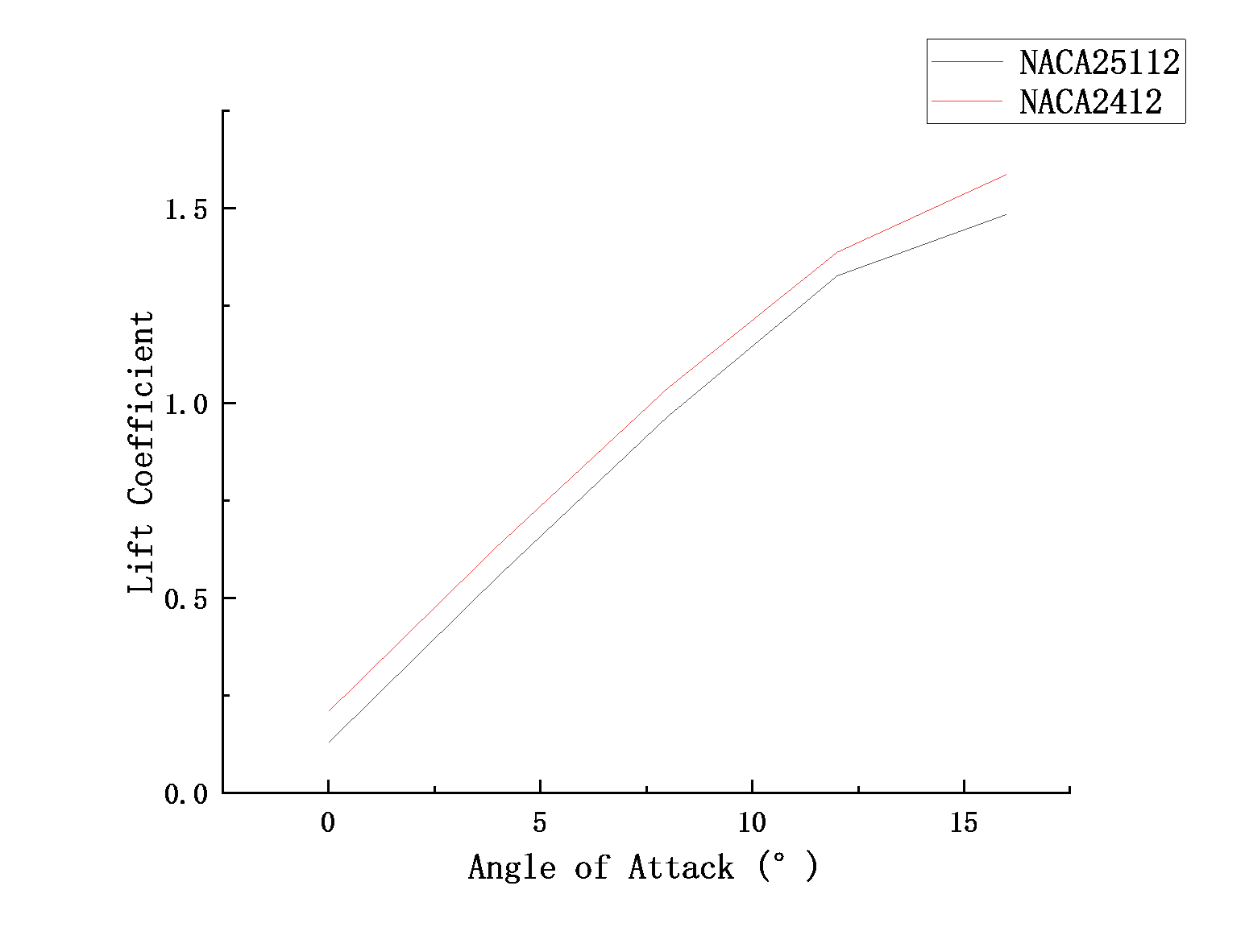
Figure 9: Lift Coefficient vs Angle of Attack
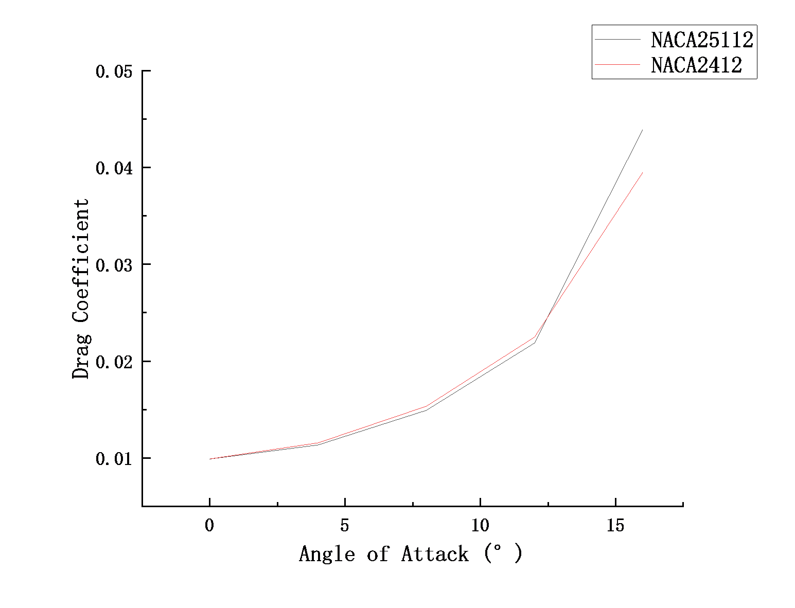
Figure 10: Drag Coefficient vs Angle of Attack
4. Conclusion
This research comprehensively studies and compares the aerodynamic characteristics of NACA2412 and NACA25112 aerofoil together with ANSYS Fluent. Utilizing the Finite Volume Method in conjunction with the SST K-Omega turbulence model, simulate the 2 D flow properties of the wing numerically. The performance of NACA2412 and NACA25112 is analysed in detail from the aspects of pressure distribution, velocity distribution, drag coefficient vs attack angles, lift coefficient vs angles and so on Make a conclusion based on the experimental results conclusions are:
(a)With increasing angle of attack, NACA2412 and NACA25112 showed consistent results in pressure distribution and velocity distribution.
(b)The variation of the attack angle has a great influence on the pressure and velocity of the wing
However, in the research, fluid was set as air, which means it only considers the aerofoils in the air, ignoring conditions close to the ground or near water. More situations will be done in the follow-up study. In addition, more influencing factors can be added to the experiment, such as material, temperature change, etc., to make the simulation results more accurate.
In the future, limitations will be improved, such as finer angles of attack, more fluid types, mounting the wing on a solid body for testing, simulate as many possible scenarios as possible. Meanwhile, more attack angles will be considered. The relationship between the aerodynamic characteristics of NACA2412 and NACA25112 over a larger range and the Angle of attack will be explored. The experimental results will be used as a reference in subsequent physical experiments and wind tunnel tests to help develop new aerofoils or improve existing aerofoils. At the same time, the comparison materials between NACA2412 and NACA25112 are enriched, which provides some convenience for the need to consult relevant literature in the future.
References
[1]. Mangano M, Martins J R R A. Multipoint aerodynamic shape optimization for subsonic and supersonic regimes[J]. Journal of Aircraft, 2021, 58(3): 650-662.
[2]. Conlan-Smith C, Ramos-García N, Sigmund O, et al. Aerodynamic shape optimization of aircraft wings using panel methods[J]. AIAA Journal, 2020, 58(9): 3765-3776.
[3]. Shabur A, Hasan A, Ali M. Comparison of aerodynamic behaviour between NACA 0018 and NACA 0012 aerofoils at low Reynolds number through CFD analysis[J]. Advancement in Mechanical Engineering and Technology, 2020, 3(2): 1-8.
[4]. Dhakal S, Bhattarai K R, Sanjay M. Computational Analysis of the Aerodynamic Performance of NACA 4412 and NACA 23012 Airfoils[J]. 2023.
[5]. Kepekci H. Comparative Numerical Aerodynamics Performance Analysis of NACA0015 and NACA4415 Airfoils[J]. International Journal of Engineering, Science and Information Technology, 2022, 2(1): 144-151.
[6]. Kaya M N, Kok A R, Kurt H. Comparison of aerodynamic performances of various aerofoils from different aerofoil families using CFD[J]. Wind and Structures, 2021, 32(3): 239-248.
Cite this article
Liu,X. (2025). Computational Simulation of the Aerodynamic Performance of NACA2412 andNACA25112 in Low Reynolds Numbers. Applied and Computational Engineering,130,130-139.
Data availability
The datasets used and/or analyzed during the current study will be available from the authors upon reasonable request.
Disclaimer/Publisher's Note
The statements, opinions and data contained in all publications are solely those of the individual author(s) and contributor(s) and not of EWA Publishing and/or the editor(s). EWA Publishing and/or the editor(s) disclaim responsibility for any injury to people or property resulting from any ideas, methods, instructions or products referred to in the content.
About volume
Volume title: Proceedings of the 5th International Conference on Materials Chemistry and Environmental Engineering
© 2024 by the author(s). Licensee EWA Publishing, Oxford, UK. This article is an open access article distributed under the terms and
conditions of the Creative Commons Attribution (CC BY) license. Authors who
publish this series agree to the following terms:
1. Authors retain copyright and grant the series right of first publication with the work simultaneously licensed under a Creative Commons
Attribution License that allows others to share the work with an acknowledgment of the work's authorship and initial publication in this
series.
2. Authors are able to enter into separate, additional contractual arrangements for the non-exclusive distribution of the series's published
version of the work (e.g., post it to an institutional repository or publish it in a book), with an acknowledgment of its initial
publication in this series.
3. Authors are permitted and encouraged to post their work online (e.g., in institutional repositories or on their website) prior to and
during the submission process, as it can lead to productive exchanges, as well as earlier and greater citation of published work (See
Open access policy for details).
References
[1]. Mangano M, Martins J R R A. Multipoint aerodynamic shape optimization for subsonic and supersonic regimes[J]. Journal of Aircraft, 2021, 58(3): 650-662.
[2]. Conlan-Smith C, Ramos-García N, Sigmund O, et al. Aerodynamic shape optimization of aircraft wings using panel methods[J]. AIAA Journal, 2020, 58(9): 3765-3776.
[3]. Shabur A, Hasan A, Ali M. Comparison of aerodynamic behaviour between NACA 0018 and NACA 0012 aerofoils at low Reynolds number through CFD analysis[J]. Advancement in Mechanical Engineering and Technology, 2020, 3(2): 1-8.
[4]. Dhakal S, Bhattarai K R, Sanjay M. Computational Analysis of the Aerodynamic Performance of NACA 4412 and NACA 23012 Airfoils[J]. 2023.
[5]. Kepekci H. Comparative Numerical Aerodynamics Performance Analysis of NACA0015 and NACA4415 Airfoils[J]. International Journal of Engineering, Science and Information Technology, 2022, 2(1): 144-151.
[6]. Kaya M N, Kok A R, Kurt H. Comparison of aerodynamic performances of various aerofoils from different aerofoil families using CFD[J]. Wind and Structures, 2021, 32(3): 239-248.