


1. Introduction
1.1. Research Background and Significance
1.1.1. Background of Millimeter-Wave Channel Characteristics Research
The main attraction of the millimeter-wave (mmWave) frequency band lies in its continuous large bandwidth, which enables the provision of gigabit wireless network services. In addition, the mmWave frequency band has extremely small transmitting and receiving antenna sizes because its antenna length is proportional to the wavelength. This feature allows a large number of antenna elements to be compactly packaged in a very small space, making high antenna gains and beamforming technologies feasible in small mobile devices. In the post-5G and 6G wireless communication era, the transmission rates of wireless communications are expected to surge to Gbps levels, positioning the mmWave frequency band as one of the key technologies to address the issues of high-speed and low-latency communication.
1.1.2. Significance of Millimeter-Wave Channel Characteristics Research
As the bridge and path for signal transmission, the characteristics of the wireless channel play a crucial role in the performance of communication systems [2]. An in-depth study of mmWave channel characteristics not only enriches the means of channel modeling by introducing new models but also accelerates the process of channel standardization.
The goal of establishing a channel model is to better generate simulation channels, preparing for the evaluation of upper-layer communication technologies. Since 2012, research institutions and project groups worldwide have started work on the standardization of 5G mmWave channel models. Figure 1 shows the commonly used mmWave channel models and the applicable scope of each channel model.
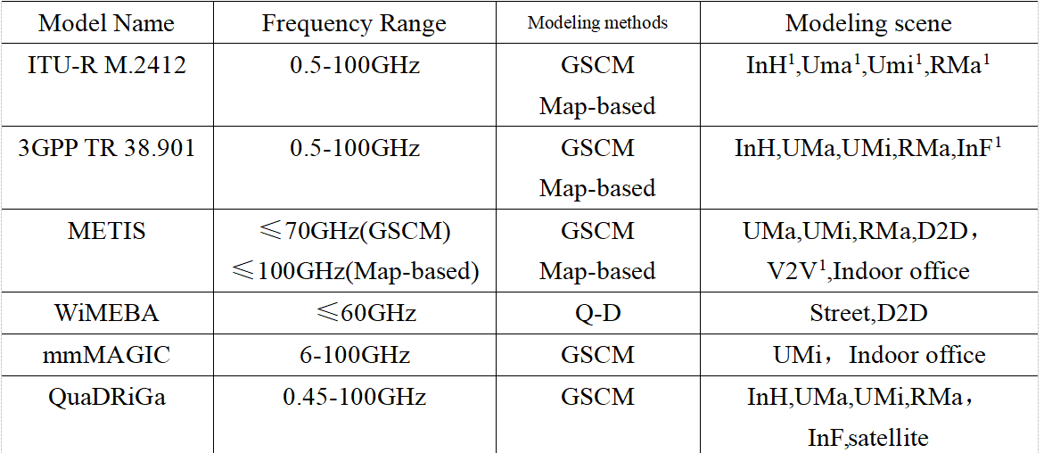
Figure 1: Commonly Used Millimeter-Wave Channel Models and Their Applicable Scope
1.2. Related Research
Work to define new channel models for millimeter waves has been extensive and ongoing. Over the past several decades, many scholars have conducted research on mmWave channel models, including deterministic, empirical, and intelligent channel models [3]. Literature [4][5] confirms the accuracy of ray-tracing methods for studying the electromagnetic characteristics of mmWave networks in factory environments. This method is applicable to various propagation environments and can provide high-precision path loss estimates. However, ray tracing has a high computational complexity and relatively low generality, which limits its practical applications [6]. The most significant advancement is the 3GPP TR 38.900 channel model, which extends existing stochastic models. Literature [7] also presents a hybrid channel model based on mapping, which combines deterministic and stochastic components. This model can be used when predicting specific environments considering structural and material factors. Many other groups are actively researching mmWave channel models, including the 5G-PPP mmMAGIC project [8]. This work includes in-depth research on six areas of the channel, including spatial consistency, blocking, clustering, ground reflection, frequency dependence, and effective channels for link-level simulation.
Due to rapid variations in path loss, timely and efficient establishment of accurate path loss models presents a significant challenge. Therefore, this paper investigates a millimeter-wave path loss model for indoor environments based on artificial neural networks. By leveraging the advantages of artificial neural networks in solving nonlinear problems, the path loss factors of large-scale path loss models in various environments are extracted. After training the neural network, a model is obtained that classifies the line-of-sight (LOS), non-line-of-sight (NLOS), and combined LOS-NLOS areas. Based on predefined thresholds, the Close-In free space reference distance path loss model (CI) or the Floating-Intercept path loss model (FI) is efficiently applied to model path loss in the LOS and NLOS areas, enhancing the real-time performance and efficiency of channel measurement and modeling.
2. Fundamental Theories
2.1. Millimeter-Wave Wireless Channel
2.1.1. Radio Wave Propagation Mechanism
The wireless channel, as the medium for radio wave propagation, defines the transmission path between the signal transmitter and receiver. The signal is radiated from the transmitter in a multipath manner, with some paths directly reaching the receiver, while other paths may be reflected, scattered, or diffracted by obstacles before reaching the receiver. As the propagation distance increases, radio waves experience greater path loss, with obstacles such as trees, buildings, and complex terrain exacerbating the path loss and causing shadow fading. Additionally, various scatterers along the propagation path, regardless of size, interfere with signal propagation, causing the received signal to be a superposition of multiple path signals. These signals differ in amplitude, phase, and arrival time, resulting in multipath effects, making the received signal different from the original transmitted signal. The movement of the mobile receiver relative to the transmitter further causes the Doppler effect. In summary, the propagation environment of radio waves is complex and variable. In the 5G era, with increasing demands for communication quality, capacity, and speed, understanding the propagation characteristics of radio waves in wireless channels becomes crucial. This is of significant importance for enhancing channel capacity and reducing spectrum resource waste [9].
2.1.2. Wireless Channel Fading Characteristics
In practical communication systems, due to the diversity of propagation mechanisms, the actual received signal is often the vector sum of signals from different paths, and thus is affected by both large-scale and small-scale fading [10].
(1) Large-Scale Fading
Large-scale fading describes the fluctuation of signal strength over long distances between the transmitter and receiver. It predicts the average received power of a wireless signal at different distances, with the distance range typically varying from hundreds of meters to thousands of meters. Path loss, as a key factor determining system coverage, can only be addressed by increasing transmission power. It, along with shadow fading, reflects the impact of the wireless channel on signal transmission over large-scale distances.
(2) Small-Scale Fading
In wireless communication, radio waves are easily disturbed by obstacles as they travel through the atmosphere, leading to multipath effects. The signal received at the receiver is the result of multiple signals with varying intensities, propagation delays, and phases being combined. Multipath effects cause signal dispersion in time, frequency, and space. When the distance between the transmitter and receiver changes by several wavelengths, the received power fluctuates significantly. This rapid fluctuation in received signal power over short time intervals and distances is known as small-scale fading. Small-scale fading primarily reflects the fading and dispersion characteristics of the wireless channel in the time, frequency, and angular dimensions. Channel parameters such as RMS delay spread, coherent bandwidth, Ricean K-factor, Doppler shift, and angular spread are commonly used to describe the small-scale fading characteristics of wireless channels.
2.2. BP Neural Network
The BP (Backpropagation) neural network is capable of solving linearly non-separable problems. It is a network that contains one or more hidden layers. The introduction of the BP algorithm solved the problem of weight updates in multilayer neural networks and greatly promoted the development of neural networks. As a result, this type of neural network is referred to as a BP neural network. The most basic BP neural network is a three-layer network, including one input layer, one output layer, and one hidden layer, with the hidden layer also potentially having multiple layers. The topology of a three-layer BP neural network is shown in Figure 2.
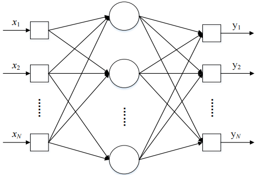
Figure 2: Structure of a BP Neural Network
The BP neural network has the following characteristics:
(1) BP neural networks have a multi-layer design with full connections between layers but no connections within layers. This design allows for the extraction of more information from large data and the completion of complex modeling.
(2) BP networks require activation functions, commonly using linear or sigmoid functions. The sigmoid function may be either Log-Sigmoid or Tan-Sigmoid, depending on whether the output contains negative values [11].
(3) The BP neural network uses the error backpropagation algorithm for learning. Data is passed layer by layer through the hidden layers, and weights are progressively adjusted in the direction of decreasing error from the output layer. As learning progresses, the error gradually decreases until the set threshold or iteration count is reached, at which point the network stops training.
3. Millimeter-Wave Channel Modeling Based on BP Neural Network
This paper models the millimeter-wave large-scale path loss characteristics using the BP neural network learning algorithm to learn channel parameters and classify propagation environments. In indoor environments, the path loss model is influenced by LOS (Line of Sight) and NLOS (Non-Line of Sight) regions, with different models used in each case. In the LOS region, single-slope CI or FI models are commonly employed. In environments where both LOS and NLOS coexist, the model is influenced by multipath effects, and the NLOS region typically requires a piecewise model. The BP neural network learning algorithm used in this paper is shown in Figure 3. The process of building and training the neural network is generally divided into three parts: preprocessing of input data, construction and training of the neural network structure, and neural network testing.
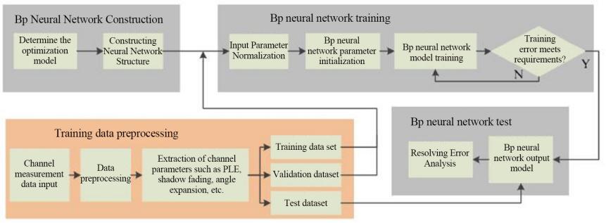
Figure 3: BP Neural Network Learning Algorithm Process
3.1. BP Neural Network Input Data Processing
During the training of the neural network, the size and diversity of the data directly affect the model’s performance. Insufficient data can reduce the prediction accuracy and applicability. In channel measurements, it is difficult to measure the same scenario multiple times, but shadow fading can reflect the large-scale path loss fluctuation. Therefore, theoretically, shadow fading can be used to randomly augment the path loss measurement data to obtain more training data. In this paper, when distinguishing between different environmental path loss models, a piecewise extraction method is used to extract the characteristics of path loss factors in various measurement environments. First, the path loss factors of each set of measurement data are extracted piecewise, and the gradient of the path loss factor between adjacent segments is calculated. Then, the extracted path loss factors and gradients are used as input parameters for the BP neural network to learn and train. Finally, by combining the corresponding small-scale channel parameters and threshold values, the system classifies different propagation environments.
This paper uses the phenomenon of shadow fading to augment the millimeter-wave path loss measurement dataset, providing more material for the training data. Using the piecewise extraction method, we extract the path loss factors in different distance ranges for each data set and use these factors as input parameters for the BP neural network. Additionally, we can use actual measurement data from existing papers as validation and testing datasets to verify the performance of the trained BP neural network.
3.2. Neural Network Construction and Training
In constructing the BP neural network, it is necessary to design the neural network structure, optimization parameters, optimization goals, and other parameters. During the training process, the input data is first normalized to prevent issues such as inaccurate numerical solutions caused by large differences in the scale of the input data. In the BP neural network initialization process, the weights and thresholds of the hidden layer are random, but they are continuously learned, optimized, and adjusted based on the error values until the output layer error reaches the set requirements, at which point the neural network training is complete. In the classification training of the BP neural network in this paper, the optimization algorithm used is the Levenberg-Marquardt (LM) algorithm. The LM algorithm combines the features of the steepest gradient descent and the Gauss-Newton method, and introduces a damping factor to adjust the algorithm, ensuring fast local convergence while maintaining overall convergence in the global range.
3.3. Neural Network Testing
The BP neural network trained in this paper is tested using existing path loss measurement results from the literature, and the model errors and fitness are analyzed. Experimental results can be referenced from [12], where the trained BP neural network can accurately differentiate between the corridor propagation environment with only the LOS region and the complex office environment with both LOS and NLOS regions. It can be observed that the neural network can effectively distinguish between various typical propagation environments.
3.4. Adaptive Neural Network Modeling
Since different regions have different modeling methods, to more accurately build the channel model, the system can adopt the corresponding modeling method based on the classification results of the BP neural network for each region. The system first processes the input large-scale path loss data, extracts features, and classifies the measurement scenario using the trained BP neural network. If the classification is a Line of Sight (LOS) region, the system will decide to use either the Constant Loss (CI) model or the Frequency Independent (FI) model based on the input frequency and path loss shadow fading threshold. If the classification is a Non-Line of Sight (NLOS) region, the system will automatically use the FI model for large-scale path loss modeling. For environments where both LOS and NLOS coexist, the system uses regularization techniques to determine the breakpoints of the piecewise model and outputs the corresponding piecewise model. After outputting the adaptive model, the system also allows further adjustment and correction of the model based on supplementary input parameters.
4. Conclusion
The rise in millimeter-wave frequencies affects the loss characteristics, leading to rapid changes in path loss, making accurate modeling a challenge. This paper proposes the use of artificial neural networks to study indoor millimeter-wave path loss models, extract large-scale path loss features, and train neural network models capable of classifying LOS, NLOS, and mixed regions. Based on threshold values, the CI or FI models are selected for efficient modeling, improving real-time performance and efficiency. However, BP neural network modeling requires a large amount of training data, and current data is insufficient. Additionally, further research is needed to refine environmental classification. Supplementary measurements can be conducted based on existing studies to acquire more data, enrich channel characteristic data, and build a more comprehensive adaptive millimeter-wave channel modeling system to meet the needs of new wireless technologies.
References
[1]. Rappaport, T. S. (2001). Wireless communications: Principles and practice. Prentice Hall.
[2]. 3GPP. (2018). 3GPP TR 38.815 V15.0.0: Technical Specification Group Radio Access Network; New frequency range for NR (24.25-29.5 GHz) (Release 15). 3GPP.
[3]. Shafi, M., Molisch, A. F., Smith, P. J., & others. (2017). 5G: A tutorial overview of standards, trials, challenges, deployment, and practice. IEEE Journal on Selected Areas in Communications, 35(6), 1201–1221.
[4]. Zhou, S., Bian, B., Chen, Z., & others. (2022). Wireless channel simulation platform for industrial environments based on 3D ray tracing. In 2022 IEEE/CIC International Conference on Communications in China (ICCC) (pp. 383–388). IEEE.
[5]. da Silva, H. T. P., de Alencar, M. S., & Assis, K. D. R. (2019). Path loss and delay spread characterization in a 26 GHz mmWave channel using the ray tracing method. In 2019 SBMO/IEEE MTT-S International Microwave and Optoelectronics Conference (IMOC) (pp. 1–3). Aveiro, Portugal.
[6]. Karabulut Umur, A., Awada, A., Viering, I., & others. (2018). Spatial and temporal channel characteristics of the 5G 3D channel model with beamforming for user mobility investigations. IEEE Communications Magazine, 56(12), 38–45.
[7]. METIS channel model. (2015). METIS 2020, ICT-317667-METIS/D1.4. METIS.
[8]. Gu, C., & Liu, Y. (n.d.). Research on path loss modeling in industrial internet scenarios. Wireless Communication Technology.
[9]. Shikhantsov, S., Guevara, A., Thielens, A., & others. (2021). Spatial correlation in indoor massive MIMO: Measurements and ray tracing. IEEE Antennas and Wireless Propagation Letters, 20(6), 903–907.
[10]. Millimetre-Wave Based Mobile Radio Access Network for Fifth Generation Integrated Communications https://5g-mmmagic.eu/.
[11]. Duan, K. Y. (2021). Research on high-frequency band channel modeling for 5G and beyond application scenarios (Master’s thesis). Wuhan University of Technology.
[12]. Cheffena, M. (2016). Propagation channel characteristics of industrial wireless sensor networks [Wireless corner]. IEEE Antennas and Propagation Magazine, 58(1), 66–73.
Cite this article
Zhou,R. (2025). A Study on Neural Network-Based Millimeter-Wave Path Loss Modeling for Indoor Application Scenarios. Applied and Computational Engineering,100,171-177.
Data availability
The datasets used and/or analyzed during the current study will be available from the authors upon reasonable request.
Disclaimer/Publisher's Note
The statements, opinions and data contained in all publications are solely those of the individual author(s) and contributor(s) and not of EWA Publishing and/or the editor(s). EWA Publishing and/or the editor(s) disclaim responsibility for any injury to people or property resulting from any ideas, methods, instructions or products referred to in the content.
About volume
Volume title: Proceedings of the 5th International Conference on Signal Processing and Machine Learning
© 2024 by the author(s). Licensee EWA Publishing, Oxford, UK. This article is an open access article distributed under the terms and
conditions of the Creative Commons Attribution (CC BY) license. Authors who
publish this series agree to the following terms:
1. Authors retain copyright and grant the series right of first publication with the work simultaneously licensed under a Creative Commons
Attribution License that allows others to share the work with an acknowledgment of the work's authorship and initial publication in this
series.
2. Authors are able to enter into separate, additional contractual arrangements for the non-exclusive distribution of the series's published
version of the work (e.g., post it to an institutional repository or publish it in a book), with an acknowledgment of its initial
publication in this series.
3. Authors are permitted and encouraged to post their work online (e.g., in institutional repositories or on their website) prior to and
during the submission process, as it can lead to productive exchanges, as well as earlier and greater citation of published work (See
Open access policy for details).
References
[1]. Rappaport, T. S. (2001). Wireless communications: Principles and practice. Prentice Hall.
[2]. 3GPP. (2018). 3GPP TR 38.815 V15.0.0: Technical Specification Group Radio Access Network; New frequency range for NR (24.25-29.5 GHz) (Release 15). 3GPP.
[3]. Shafi, M., Molisch, A. F., Smith, P. J., & others. (2017). 5G: A tutorial overview of standards, trials, challenges, deployment, and practice. IEEE Journal on Selected Areas in Communications, 35(6), 1201–1221.
[4]. Zhou, S., Bian, B., Chen, Z., & others. (2022). Wireless channel simulation platform for industrial environments based on 3D ray tracing. In 2022 IEEE/CIC International Conference on Communications in China (ICCC) (pp. 383–388). IEEE.
[5]. da Silva, H. T. P., de Alencar, M. S., & Assis, K. D. R. (2019). Path loss and delay spread characterization in a 26 GHz mmWave channel using the ray tracing method. In 2019 SBMO/IEEE MTT-S International Microwave and Optoelectronics Conference (IMOC) (pp. 1–3). Aveiro, Portugal.
[6]. Karabulut Umur, A., Awada, A., Viering, I., & others. (2018). Spatial and temporal channel characteristics of the 5G 3D channel model with beamforming for user mobility investigations. IEEE Communications Magazine, 56(12), 38–45.
[7]. METIS channel model. (2015). METIS 2020, ICT-317667-METIS/D1.4. METIS.
[8]. Gu, C., & Liu, Y. (n.d.). Research on path loss modeling in industrial internet scenarios. Wireless Communication Technology.
[9]. Shikhantsov, S., Guevara, A., Thielens, A., & others. (2021). Spatial correlation in indoor massive MIMO: Measurements and ray tracing. IEEE Antennas and Wireless Propagation Letters, 20(6), 903–907.
[10]. Millimetre-Wave Based Mobile Radio Access Network for Fifth Generation Integrated Communications https://5g-mmmagic.eu/.
[11]. Duan, K. Y. (2021). Research on high-frequency band channel modeling for 5G and beyond application scenarios (Master’s thesis). Wuhan University of Technology.
[12]. Cheffena, M. (2016). Propagation channel characteristics of industrial wireless sensor networks [Wireless corner]. IEEE Antennas and Propagation Magazine, 58(1), 66–73.