


1. Introduction
In recent years, because the actual terrain in some remote places is very complex and steep, the manual inspection of power system is very troublesome and dangerous, which leads to a very high labor cost. Therefore, many places begin to use unmanned aerial vehicle (UAV) inspection to gradually replace manual inspection. However, it is found that after a period of work, the UAV often needs to manually replace the battery or charge the battery by connecting the interface to ensure the complete inspection work. However, due to environmental factors such as terrain and climate, this will consume a lot of time and lead to the reduction of the working efficiency of UAVs. At the same time, some places also need to invest a lot of labor costs, leading to the increase of funds, so the loss is not worth the gain. Therefore, in this environment, the research on the wireless charging method of UAVs is particularly important and necessary.
From the perspective of practical application, this paper firstly introduces the wireless charging methods of UAV, then analyzes the wireless charging methods under different compensation methods, and then compares their different characteristics. Finally, it realizes the future development and progress direction of UAV wireless charging in the field of power detection.
2. Introduction to wireless charging of drones
2.1. Analysis of the status quo of UAV application
First of all, in terms of UAV equipment, UAV has many advantages that conventional equipment does not have. Compared with other equipment, UAV has high flexibility and is rarely restricted by the terrain environment, so it can achieve many goals and tasks that are difficult for human to complete. On the other hand, most UAVs have highly clear camera modules, which can ideally detect target objects in patrol inspection, so they can basically replace manual input in power inspection. However, at the same time, the author can notice that most UAVs are light and small in size. Although they are easy to carry, this also leads to the problems of small power capacity and short battery life. In addition, there are two modes for UAVs currently in use: battery replacement and manual plug charging. Both of these methods restrict the application scope of UAVs to a small area and prevent them from carrying out large cross-area tasks. Therefore, the application of UAVs in work is greatly limited, and the working efficiency is reduced. Moreover, the purpose of reducing manual input cannot be realized.
2.2. Introduction of wireless charging methods
Currently, most wireless charging methods rely on three fields: electromagnetic induction, electromagnetic magnetic resonance and electromagnetic radiation. Among them, the advantage of electromagnetic induction lies in its high transmission efficiency, but its available transmission distance is short, and the academic research in this field is relatively mature. At present, wireless charging technology in this field has been widely used, mass produced and approved by the market. Electromagnetic magnetic resonance has higher transmission efficiency, and its magnetic field is weaker than electromagnetic induction, the radiation is small, so the harm is small, but it also has large volume, the problem of insufficient stability exists, which still needs to pass a large number of studies. In addition, in the field of electromagnetic radiation, laser and microwave are often inefficient when conducting wireless charging, the transmission direction is not easy to change, and it is easy to cause great harm to human body, so the application value is missing [1].
Comparing the above areas comprehensively, this paper mainly studies the electromagnetic resonance orientation technology.
In the field of electromagnetic magnetic resonance, magnetic coupling resonance wireless charging is the most widely studied and applied one. Its wireless charging system mainly consists of three different parts of the primary side excitation circuit, secondary receiving device and the power charging module. The basic principle is to input AC excitation current into the transmitting coil on the primary side, which can produce alternating magnetic field, and achieve the goal that converts electrical energy into magnetic energy. In the second step, another coil located on the secondary side of the receiving circuit is coupled to the alternating magnetic field generated in the previous step, thus achieving the transition from magnetic force to electrical energy. Finally, the electric energy is transmitted to the device by means of power transmission, and it can be charged without wires, so as to achieve the ultimate purpose of charging. In the whole circuit of realizing magnetic coupling resonance, we can change the parameters of the components in the circuit, put the transmitter and receiver at the same resonant frequency, so as to improve the efficiency and ability of the whole working system. At present, most mainstream research directions are to change and design the coil, so as to improve the charging power and charging efficiency of the device and improve its coupling capability.
In the field of wireless charging, the commonly used compensation methods are as follows: initial side series, secondary side series (series-series, SS); primary edge in series, secondary edge in parallel (SP); initial edge parallel, secondary edge parallel (parallel-parallel, PP); and the final initial edges in parallel, secondary edges in series (PS) [2]. For SP compensation, there is reactive reactance, so we can change the reactive reactance to affect the load resistance, and then change the power factor of the entire circuit to improve the efficiency of the system. For SS compensation, its reaction resistance is pure resistance, so the power factor will not change basically, and SS is constant current [3].
In addition, at present, in the field of constant current and constant voltage wireless charging of MCR-WPT, its implementation approaches can be basically divided into two categories, including dynamic regulation method and variable static compensation method. The dynamic regulation method is mainly to add DC-DC conversion circuit, frequency conversion control and other ways in the primary or secondary side. Although these methods have high control accuracy, wide range of adjustment, and most of them only need a small space to be used, there are also other problems. Due to the need of communication between the original and the pair, this greatly increases the cost of equipment and the difficulty of operation, at the same time, the stability of the system is also affected, being easy to cause frequency division phenomenon. The variable-static compensation method mainly has hybrid compensation and so on. Generally, passive resonant network with CC or CV output characteristics is used to combine to achieve constant current and constant voltage output of the system. This method is easy to cause the problem of high cost and the output efficiency of the system is generally low [4].
3. Analysis and comparison of different wireless charging methods
3.1. Self-resonant ZVS topology
Compared with traditional wireless charging methods, ZVS self-resonant topology of UAV wireless charging has the characteristics of higher operating frequency and larger charging power, so it can reduce the time of UAV wireless charging and effectively reduce the volume of the receiver coil of UAV. In addition, it can reduce the no-load operation loss of the circuit and improve the efficiency. The ZVS topological wireless charging system uses magnetic resonance transmission mode, which transmits energy through electromagnetic coupling. In addition, two coupled resonant coils with high quality factor are added to the system to generate a stronger magnetic field. This method makes the power transmission increase, compared with the traditional model, which is more suitable for medium range transmission occasions. Therefore, the problem of UAV range is solved.
The whole wireless charging module consists of three parts, which are the transmitter of the platform, the coupling network, and the receiver of the UAV. The transmitting end of the platform includes power supply, rectifier filter circuit and ZVS circuit. Its basic principle is as follows: the alternating current in the power supply is converted into direct current through the rectifier filter circuit, and then into high-frequency alternating current through the ZVS circuit, and then it is transmitted to the next coupling network module. The coupling network is also composed of two parts, namely the primary transmitting coil and the secondary receiving coil. The primary transmitting coil uses the principle of electromagnetic induction to transmit high-frequency alternating current to the secondary coil, and then the secondary coil transmits the induced alternating current to the final receiver of the UAV. The receiving end of the UAV includes rectifier filter circuit, DC-DC converter and battery. Through the last module, the high-frequency alternating current transmitted from above can be converted into direct current, and then the voltage of the battery module can be adjusted to complete the charging task.
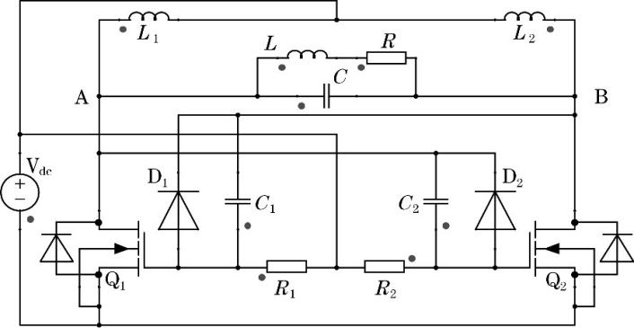
The working principle of ZVS is as follows: when the power supply starts, the Vdc provides the gate driving voltage of Q1 and Q2 and charges the capacitor. At the beginning, pipes Q1 and Q2 are in the conduction state, and the gate voltage is discharged through D1 and D2 ground conduction. However, due to the different components, one of Q1 and Q2 will be turned off first because the driving voltage is too small. After that, the two capacitors are rapidly charged and discharged, and the rapid switching of Q1 and Q2 is realized through the role of D1 and D2. In this way, work efficiency can be improved, power loss can be reduced, and the circuit can also realize self-startup. Q1 and Q2 are both in the power supply, will be turned from closed to open, so that the current can flow through L1, L2 and make the resonant circuit began to vibrate. It should be noted that Q1 and Q2 cannot be always on when the ZVS circuit is working [5].
|
Figure 1. Topology diagram of novel self-resonant ZVS. |
3.2. Double LCCL topology
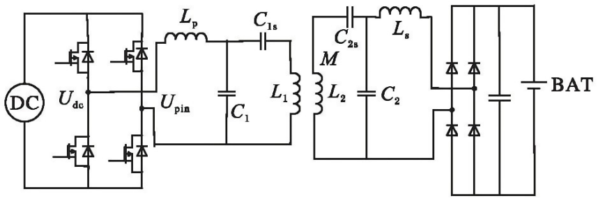
Compared with other wireless charging methods, the advantages of the dual LCCL topological resonance compensation network are that its transmitter can provide constant current characteristics and has a unit power factor. At the same time, compared with the ordinary LCL resonant compensation network, the LCCL resonant compensation network has a compensation capacitor, which can be used to adjust the current of the transmitting coil and avoid the phenomenon of magnetization caused by the current at the transmitting end. Compared with other modes, the selection of component parameters in this mode is also more flexible.
The UAV wireless charging system of dual LCCL topological resonance compensation network is shown in the figure: where, the LCCL resonant circuit at the transmitter is composed of inductor Lp, capacitor C1, capacitor C1s, and primary coil L1. The LCCL resonant circuit at the receiving end will be composed of inductor L2, capacitor C2, capacitor C2s, and the original side coil Ls. At first, the Alternating current-direct Current (AC-DC) converter will be used to generate the DC Current source Udc. Then it is converted into high frequency AC square wave Upin by phase-shifting full bridge inverter circuit. After passing through the double LCCL resonant compensation circuit at the transmitter, a constant excitation current will be generated in the coil. The current can generate an induced electromotive force in the receiving coil by magnetic field coupling and pass through the double LCCL optical compensation circuit at the receiving end. Finally, through the AC-DC rectifier circuit, it has obtained the final direct current to realize the charge of lithium battery [6].
|
Figure 2. Schematic of wireless charging system for UAV with dual LCCL resonance compensation. |
3.3. LCL-LCL /S hybrid self-switching resonant wireless charging system
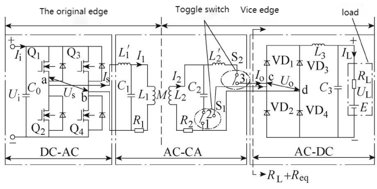
Since it is difficult to complete the constant-current and constant-voltage output of the secondary edge when the input impedance of the original edge is purely resistive by relying only on the resonant topology formed by the T-type network, the hybrid self-switching resonant LCL-LCL/S network topology combining the output characteristics of the second-order and third-order networks is needed.
As shown in the figure, the original side of the resonant network is all single-phase full-bridge high-frequency inverter circuit. The LCL resonance network at the transmitter is composed of L1 ', L1, R1 and C1, and M is the mutual inductance between the transmitter coil and the receiver coil. The secondary side is a single-phase uncontrolled high-frequency rectifier circuit mainly used for inductance and capacitor filtering, which consists of VD1, VD2, VD3 and VD4. The LCL resonance network at the receiver is composed of L2 ', L2, R2 and C2, and L2, R2 and C2 constitute the S resonance network at the receiver. L3 and C3 are the filter inductance and filter capacitor of the circuit, and the charging load of the whole battery is composed of RL and E, which is equivalent to the reverse electromotive force load.
When S1 is connected to contact 1 and S2 is connected to contact 3, the system is LCL-LCL type resonant topology, and the whole system works in CC mode. When S1 is connected to contact 2 and S2 is disconnected from contact 3, the system is LCL-S type resonant topology, and the whole system works in CV mode. In the process of switching, the resonant frequency of the system will remain unchanged. As a result, the system realized by monitoring the size of the load side voltage to adjust the working status of the S1, S2, the purpose of, and thus can realize the LCL - type LCL resonant topology and LCL - S type two kinds of system of switching resonant topology, which has realized under the condition of the frequency remains unchanged, the switch between CC and CV model.
Therefore, this method can reasonably solve the situation of excessive use of switches and too many passive components in other variable and static compensation methods, and the selection of parameters will be relatively simple, which greatly simplifies the control system and improves the transmission efficiency, and has high application value [4].
|
Figure 3. LCL-LCL /S resonant network topology. |
3.4. Solar-powered wireless charging of drones
The design of the system combines solar charging technology with wireless charging technology, STC90C58AD microcontroller is used as the main controller of the whole system, which has the functions of detecting the voltage of the system, charging and releasing protection of the battery and switching control of the UAV and the battery. At the same time, the PCF8591 digital-to-analog conversion module is used to sample and collect information about the voltage of the system and the external light source. Finally, the single-chip microcomputer is used to control the charge and discharge of the battery.
The whole system uses wireless charging module, chopper circuit module, LM7805 voltage regulator circuit, LM338 adjustable voltage regulator circuit, NE555 driver single bridge circuit and other modules to achieve the purpose of wireless charging UAV.
In addition, the input terminal of magnetic coupling resonance wireless transmission system is composed of access signal source, signal generator and power amplifier. In terms of charging equipment, solar charging equipment uses storage batteries for charging. Therefore, the whole module selects DC signal as the access signal of the transmission system, which is transmitted to the signal generator, and then generates high-frequency signal through the power amplifier circuit, and finally transmitted to the output coil [7].
4. Conclusion
The application of wireless charging in the UAV power circuit system is very important and practical, because it can greatly save the labor cost and reduce the cost of manual work in the hostile environment. The design methods of these wireless charging systems are proposed to improve the charging and transportation efficiency of unmanned aerial vehicles (UAVs) and to solve the difficulties in the practical use of UAVs. These methods can more reasonably solve the problem that UAV is limited by region when conducting power grid patrol inspection, especially in the region with long line distribution, geographical environment and steep environment, and can better reflect their role in improving the safety and efficiency of power system line detection. Similarly, there are still many other problems in the electrical inspection of UAVs. 1. In the case of heavy rain and rain, most UAVs cannot take protective measures immediately during line inspection to reduce the damage to UAVs. 2. The construction of wireless charging system requires a large amount of capital. Therefore, deeper innovations in material and institutional construction are needed to save input costs. 3. After completion of the whole wireless charging system, for the maintenance and maintenance of the whole system is very important, especially in the different regions of the environment temperature, pressure, humidity, etc. Will have obvious different, thus increase the security of wireless charging system follow-up needs more experimental optimization, to prolong the service life of the whole system. Therefore, the application of wireless charging in UAV power inspection still has a long way to go, which is also a development goal and direction in the future.
References
[1]. Zhang Hongsheng, Tian Xiaowei, Liu Zhongcheng, etc. Unmanned aerial vehicle wireless energy transfer technology. Seahawk Aviation General Equipment Co., LTD. 2018.
[2]. Huang Xueliang, Wang Wei, Tan Linlin etc. Research trends and application prospects of magnetic coupling resonant radio energy transmission technology. School of Electrical Engineering, Southeast University 2017.
[3]. Ma Xiujuan, Wu Shuai, CAI Chunwei, etc. Research on wireless charging technology applied to UAV. School of Information Science and Engineering, Harbin Institute of Technology (Weihai) 2019.
[4]. Guo Xing, Liu Liqiang, Qi Yongsheng, etc. Based on LCL-LCL/S hybrid self-switching resonant wireless charging system. College of Electric Power, Inner Mongolia University of Technology 2022.
[5]. Zhang Di, Zhang Shijie, Wang Jingyun, etc. Application of self-resonant ZVS in UAV wireless charging system. School of Electrical and Electronic Engineering, Huazhong University of Science and Technology 2019.
[6]. Zhong Wenqi, Liu Da, Guan Bin etc. Parameter design of UAV wireless charging based on dual LCCL topology. College of Electronic Information and Automation, Civil Aviation University of China 2020.
[7]. Ma Haixia, Lin Yuyuan, Liang Hengsheng, etc. Design of solar-powered wireless charging device for UAV. School of Electrical Engineering, Guangzhou College, South China University of Technology 2021.
Cite this article
Hong,Y. (2023). Application of wireless charging in UAV line patrol. Applied and Computational Engineering,4,7-12.
Data availability
The datasets used and/or analyzed during the current study will be available from the authors upon reasonable request.
Disclaimer/Publisher's Note
The statements, opinions and data contained in all publications are solely those of the individual author(s) and contributor(s) and not of EWA Publishing and/or the editor(s). EWA Publishing and/or the editor(s) disclaim responsibility for any injury to people or property resulting from any ideas, methods, instructions or products referred to in the content.
About volume
Volume title: Proceedings of the 3rd International Conference on Signal Processing and Machine Learning
© 2024 by the author(s). Licensee EWA Publishing, Oxford, UK. This article is an open access article distributed under the terms and
conditions of the Creative Commons Attribution (CC BY) license. Authors who
publish this series agree to the following terms:
1. Authors retain copyright and grant the series right of first publication with the work simultaneously licensed under a Creative Commons
Attribution License that allows others to share the work with an acknowledgment of the work's authorship and initial publication in this
series.
2. Authors are able to enter into separate, additional contractual arrangements for the non-exclusive distribution of the series's published
version of the work (e.g., post it to an institutional repository or publish it in a book), with an acknowledgment of its initial
publication in this series.
3. Authors are permitted and encouraged to post their work online (e.g., in institutional repositories or on their website) prior to and
during the submission process, as it can lead to productive exchanges, as well as earlier and greater citation of published work (See
Open access policy for details).
References
[1]. Zhang Hongsheng, Tian Xiaowei, Liu Zhongcheng, etc. Unmanned aerial vehicle wireless energy transfer technology. Seahawk Aviation General Equipment Co., LTD. 2018.
[2]. Huang Xueliang, Wang Wei, Tan Linlin etc. Research trends and application prospects of magnetic coupling resonant radio energy transmission technology. School of Electrical Engineering, Southeast University 2017.
[3]. Ma Xiujuan, Wu Shuai, CAI Chunwei, etc. Research on wireless charging technology applied to UAV. School of Information Science and Engineering, Harbin Institute of Technology (Weihai) 2019.
[4]. Guo Xing, Liu Liqiang, Qi Yongsheng, etc. Based on LCL-LCL/S hybrid self-switching resonant wireless charging system. College of Electric Power, Inner Mongolia University of Technology 2022.
[5]. Zhang Di, Zhang Shijie, Wang Jingyun, etc. Application of self-resonant ZVS in UAV wireless charging system. School of Electrical and Electronic Engineering, Huazhong University of Science and Technology 2019.
[6]. Zhong Wenqi, Liu Da, Guan Bin etc. Parameter design of UAV wireless charging based on dual LCCL topology. College of Electronic Information and Automation, Civil Aviation University of China 2020.
[7]. Ma Haixia, Lin Yuyuan, Liang Hengsheng, etc. Design of solar-powered wireless charging device for UAV. School of Electrical Engineering, Guangzhou College, South China University of Technology 2021.