


1. Introduction
The 4-Link Robotic Simulator is a simulation program in MATLAB developed by David and Fumiya from the University of Cambridge [1]. This research is to increase the step size of the robot in the simulator while keeping the stability of the locomotion. The stableness of the system is always affected by the position of the center of mass. When we adjust the length of the links, the step size will be affected, the center of mass will also be influenced, and the zero-moment point will be altered. But the method to tweak the stability of the 4-Link Robotic Simulator is still unknown. The target of the research is to find the optimized relation of the lengths of different links, such that the robot will be moving in a larger step and in a stable state. The report includes the comparison of the original geometries and parameters of the 4-Link Robot with those of the modified version. Based on this, a few tables of the link lengths and the angles of the robot will be listed, and a few graphs simulating the locomotion state of the robot will be provided.
2. Related works
2.1. 4-Link Robotic Simulator
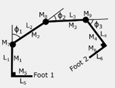
The 4-Link Robotic Simulator has 6 main simulation modes including “MANUAL STRIDE, INVERSE KINEMATICS, KALMAN FILTERING, Q-LEARNING, SIMULATED ANNEALING, and WALKING USING SIMULATED ANNEALING” [1]. Figure 1 shows the basic geometries of the 4-Link Robot. L1 to L6 means it has 6 links, while L5 and L6 are the robot’s feet. When the robot moves, the angles ф1, ф2, and ф3 vary between 90 degrees and 60 degrees to expand the links, such that foot 2 will extend forward. And in the meantime, the included angle between the L1 and L5 and the included angle between L4 and L6 will be kept at 90 degrees. To manually set the geometric parameters of the robot and to test the stride length, the MANUAL STRIDE mode will be utilized.
|
Figure 1. Geometry of 4-Link Robotic Simulator. |
2.2. Minimal models of locomotion robots
One of the simplest models of robots with legged locomotion is the Compass Gait Model found by Goswami et al. [2]. It is a two-degree-of-freedom biped that can walk passively and steadily down an incline without any actuation. The locomotive method for this model is passive dynamic walking, as the model does not rely on any other exterior energy but gravity.
Another model worth noting here is Spring-Mass Running Model, it is first introduced by McMahon and Cheng [3]. The model is composed of an inverted pendulum with a spring connected to the ground. Based on this model, two sets of equations defining two phases were derived, the first is the flight phase, and the second is the stance phase. Then the model was further developed by Geyer et al. [4]. They found the Spring-Mass Walking Model based on the running model.
Based on all the models introduced further, their stable state can be determined by the position of zero moment point (ZMP) proposed by Vukobratović and Stepanenko [10]. ZMP means the sum of all the moments is zero. The model can be stable as long as the ZMP is lying under the supporting polygon area of the model.
2.3. The increased step size stability assessment
According to Aller et al., the research paper I3SA: The Increased Step Size Stability Assessment Benchmark and its Application to the Humanoid Robot REEM-C proposed Increased Step Size Stability Assessment (I3SA) to test the stability of a humanoid robot REEM-C [5].
The experiment starts at 20% of the total length of the robot’s leg as an initial step. Then the step size is kept increasing to 40% of the total length of the leg. Parameters relating to capture point, foot placement estimator, and the angular momentum acting at the center of mass is recorded and analyzed. As Herr et al.[6] proposed, that the reactional force that comes from the ground can make the angular momentum oscillate. The experimenters also found the safety limit of the angular moment and angular velocity that prevent the robot from falling. The fall of the REEM-C happens when the max angular velocity of the stance foot reaches 40 rad/s and the max normalized angular momentum reaches 0.14 1/s.
2.4. Advanced methods to maintain stability
Shkolnik et al. developed a hybrid controller to maintain the stability of a quadruped robot LittleDog with multiple degrees of freedom [7]. Most of the violation of the static stability was diminished while the robot was still on the intended trajectory. Tedrake et al. applied a statistical method to approximate the stability of the robot by investigating the mean first passage time (MFPT) [8]. Dutta et al. designed an electrical feedback circuitry with force sensors to adjust the angle of the ankle of the robot to maintain a stable state [9].
3. Methods
The stableness of the 4-Link Robot will be determined by observing the moving process shown in the simulation figures through MATLAB. In the code part, two main M-files from MATLAB with multiple commands will be utilized: the “StandardStartingParameters.m” is used to adjust the length of the links, and the “manualstride.m” is used to simulate the walking process of the robot in five steps.
Four sets of inputs of geometric parameters of the robot will be made. The first data set will be the original parameters of the link length of the robot: lengths of L1 and L4 equal to 1.2, lengths of L2 and L3 equal to 1.4, and lengths of L5 and L6 equal to1.5. The other three sets are the modified parameters of the link length. In the second data set, lengths of L1 and L4 and L5 and L6 remain the same. Only the lengths of L2 and L3 will be changed to 3. In the third data set, the lengths of L1 and L4 will be unchanged, and the lengths of L2 and L3 will be the same as in the second data set, but the L5 and L6 will be adjusted to 3.1. For the last data set, only the lengths of L5 and L6 will be modified. The last trial is the most important, as we are trying to find the limit to differentiate between the stable and unstable states. To control other values, the mass and the included angle between links will not be changed.
The measurement of specific parameters including the total moving lengths, step size, and link length is made directly in the MATLAB figures. The start position is at (-2,0). Then the comparison tables will be made using Microsoft Excel. The MATLAB program can also show the stability of the locomotion. The red background color shows the unstable behaviors of the robot. A number of figures of MATLAB results for the locomotion processes will be shown afterward.
A few trials of simulation of different length inputs of L5 & L6 are done to analyze the stable margin for the locomotion of the robot.
Table 1. Comparison of Joint Angles.
Original | ф1, ф2, ф3 (rad) | Π/2, Π/2, Π/2 |
New | ф1, ф2, ф3 (rad) | Π/2, Π/2, Π/2 |
Table 2. Comparison of Link Length.
L1, L4 Length | L2, L3 Length | L5, L6 Length | |
Original | 1.2 | 1.4 | 1.5 |
New (First Trial) | 1.2 | 3 | 1.5 |
New (Second Trial) | 1.2 | 3 | 3.1 |
New (Third Trial) | 1.2 | 3 | 3.0065 |
4. Results
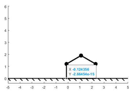
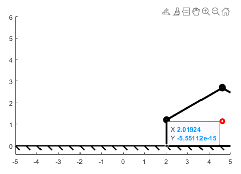
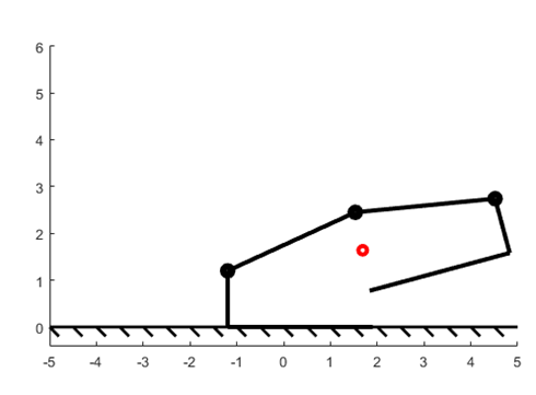
As the length of L2 and L3 increase, the step size will increase, because the total length of the distance the robot moves increases. Figure 2 and figure 3 show the difference between the final position of the joint point between L1 and L5.
|
|
Figure 2. Final Postion of L5, L6 = 1.4 | Figure 3. Final Postion of L5, L6 = 3 |
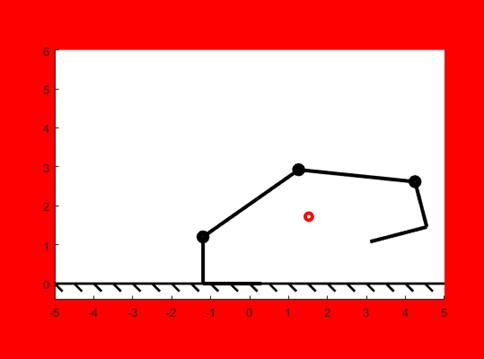
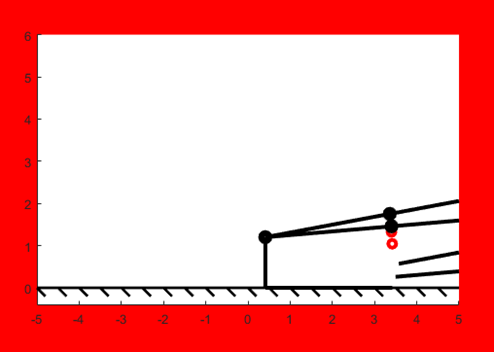
We have known that increasing the link length of L2 and L3 increase the step length. Then we have to determine the limit of the foot length – the minimum foot length (L5 and L6) to prevent it from being unstable. Figure 4, Figure 5, and Figure 6 show the simulated results of the length of L5, and L6 equal to 1.5, 3.1, and 3.0065 (Table 2). According to those figures, the correlation between the L2, L3, and the L5, L6 can be determined, which is the foot length has to be larger than the length of the L2 and L3 to make the whole locomotion stable. The critical point of the length of L5 and L6 has also been found as 3.0065. At this moment, the locomotion will be half-stable and half-unstable. Specifically, when the length of L2 and L3 is increased to 3, the foot length has to be at least 0.216% higher than the length of L2 and L3 for this case.
|
|
Figure 4. Locomotion of L5, L6 = 1.5 | Figure 5. Locomotion of L5, L6 = 3.1 |
| |
Figure 6. Locomotion of L5, L6 = 3.0065 | |
5. Discussion
The results indicate that the length of feet – L5 and L6 – should be always larger than the link length of L2 and L3 if we want stable locomotion no matter how much length the L2 and L3 are increased. In line with the zero moment point (ZMP) proposed by Vukobratović and Stepanenko, once the link lengths of L5 and L6 are larger than the lengths of L2 and L3, the ZMP is on the center part of the robot [10]. The longitudinal moment is balanced, and the sum of the moment is zero, thus, the robot is stable. Even though knowing the ZMP is enough to determine the stable state, these results should be taken into account when considering how to find the exact stable margin of the robot. The results show that the foot length should be increased at least 0.216% higher than the length of L2 and L3 when the L2 and L3 are increased to 3. This data contributes to a clearer understanding of how to find the minimum distance to be increased of the stable foot length, such that certain materials can be saved when building the robot in real situations. The generalizability of the results is limited by the virtual simulation, and there is currently no physical model to be made to test the stability of the locomotion. Further research is needed to establish the relationship between the link lengths in the physical situation, which means stability in multiple directions can be analyzed. So several parts such as controllers, motors, and springs are needed to build a real model in the future.
6. Conclusion
This research is targeted to identify the correlation between the lengths of feet and the length of links of the 4-Link Robotic Simulator to keep stable locomotion. Based on the simulation program from MATLAB, it can be concluded that the length of L5 and L6 should be not smaller than the length of the increased length of L2 and L3 to make the whole locomotion stable. We also have found the critical length (L=3.0065). The length higher than 3.0065 contributes to the stable behavior of the robot, and the length lower than it contributes to the unstable behavior. In the case in which L2 and L3 were increased to 3, the L5 and L6 should be increased 0.216% higher. This research clearly illustrates the methods to maintain stability with increased step length, but it also raises the question of maintaining stability in other directions. As this research is based on a 2-D program, only longitudinal stability can be determined in this case. To better understand the implications of these results, future studies could address the problem of maintaining stability in the lateral direction by building and testing a physical model. Through this research, the methodology used helps to solve the problem of being unstable when the step size of the 4-Link Robotic Simulator is increased. The results are also following the finding from Vukobratović and Stepanenko [10]. The increased length of the L5 and L6 construct the zero-moment point.
References
[1]. DSHardman, “DSHARDMAN/4linksimulator: MATLAB simulator for a 4-link robot, teaching basic robotic principles,” GitHub. [Online]. Available: https://github.com/DSHardman/4linksimulator. [Accessed: 23-Jun-2022]. H. Simpson, Dumb Robots, 3rd ed., Springfield: UOS Press, 2004, pp.6-9.
[2]. Goswami, A., Thuilot, B., & Espiau, B. (1996). Compass-like biped robot part I: Stability and bifurcation of passive gaits (Doctoral dissertation, INRIA).
[3]. McMahon, T. A., & Cheng, G. C. (1990). The mechanics of running: how does stiffness couple with speed?. Journal of biomechanics, 23, 65-78.
[4]. Geyer, H., Seyfarth, A., & Blickhan, R. (2006). Compliant leg behaviour explains basic dynamics of walking and running. Proceedings of the Royal Society B: Biological Sciences, 273(1603), 2861-2867.
[5]. Aller, F., Harant, M., Sontag, S., Millard, M., & Mombaur, K. (2021, September). I3SA: The Increased Step Size Stability Assessment Benchmark and its Application to the Humanoid Robot REEM-C. IROS (pp. 5357-5363). IEEE.
[6]. Herr, H., & Popovic, M. (2008). Angular momentum in human walking. Journal of experimental biology, 211(4), 467-481.
[7]. Shkolnik, A., & Tedrake, R. (2007, April). Inverse kinematics for a point-foot quadruped robot with dynamic redundancy resolution. In Proceedings 2007 IEEE International Conference on Robotics and Automation (pp. 4331-4336). IEEE.
[8]. Tedrake, R., Byl, K., & Pratt, J. E. (2006). Probabilistic stability in legged systems: Metastability and the mean first passage time (FPT) stability margin.
[9]. Dutta, S., Maiti, T. K., Miura-Mattausch, M., Ochi, Y., Yorino, N., & Mattausch, H. J. (2020). Analysis of sensor-based real-time balancing of humanoid robots on inclined surfaces. IEEE Access, 8, 212327-212338.
[10]. Vukobratović, M., & Stepanenko, J. (1972). On the stability of anthropomorphic systems. Mathematical biosciences, 15(1-2), 1-37.
Cite this article
Ji,H. (2023). Increasing step size of the 4-link robotic simulator in stable state. Applied and Computational Engineering,4,38-43.
Data availability
The datasets used and/or analyzed during the current study will be available from the authors upon reasonable request.
Disclaimer/Publisher's Note
The statements, opinions and data contained in all publications are solely those of the individual author(s) and contributor(s) and not of EWA Publishing and/or the editor(s). EWA Publishing and/or the editor(s) disclaim responsibility for any injury to people or property resulting from any ideas, methods, instructions or products referred to in the content.
About volume
Volume title: Proceedings of the 3rd International Conference on Signal Processing and Machine Learning
© 2024 by the author(s). Licensee EWA Publishing, Oxford, UK. This article is an open access article distributed under the terms and
conditions of the Creative Commons Attribution (CC BY) license. Authors who
publish this series agree to the following terms:
1. Authors retain copyright and grant the series right of first publication with the work simultaneously licensed under a Creative Commons
Attribution License that allows others to share the work with an acknowledgment of the work's authorship and initial publication in this
series.
2. Authors are able to enter into separate, additional contractual arrangements for the non-exclusive distribution of the series's published
version of the work (e.g., post it to an institutional repository or publish it in a book), with an acknowledgment of its initial
publication in this series.
3. Authors are permitted and encouraged to post their work online (e.g., in institutional repositories or on their website) prior to and
during the submission process, as it can lead to productive exchanges, as well as earlier and greater citation of published work (See
Open access policy for details).
References
[1]. DSHardman, “DSHARDMAN/4linksimulator: MATLAB simulator for a 4-link robot, teaching basic robotic principles,” GitHub. [Online]. Available: https://github.com/DSHardman/4linksimulator. [Accessed: 23-Jun-2022]. H. Simpson, Dumb Robots, 3rd ed., Springfield: UOS Press, 2004, pp.6-9.
[2]. Goswami, A., Thuilot, B., & Espiau, B. (1996). Compass-like biped robot part I: Stability and bifurcation of passive gaits (Doctoral dissertation, INRIA).
[3]. McMahon, T. A., & Cheng, G. C. (1990). The mechanics of running: how does stiffness couple with speed?. Journal of biomechanics, 23, 65-78.
[4]. Geyer, H., Seyfarth, A., & Blickhan, R. (2006). Compliant leg behaviour explains basic dynamics of walking and running. Proceedings of the Royal Society B: Biological Sciences, 273(1603), 2861-2867.
[5]. Aller, F., Harant, M., Sontag, S., Millard, M., & Mombaur, K. (2021, September). I3SA: The Increased Step Size Stability Assessment Benchmark and its Application to the Humanoid Robot REEM-C. IROS (pp. 5357-5363). IEEE.
[6]. Herr, H., & Popovic, M. (2008). Angular momentum in human walking. Journal of experimental biology, 211(4), 467-481.
[7]. Shkolnik, A., & Tedrake, R. (2007, April). Inverse kinematics for a point-foot quadruped robot with dynamic redundancy resolution. In Proceedings 2007 IEEE International Conference on Robotics and Automation (pp. 4331-4336). IEEE.
[8]. Tedrake, R., Byl, K., & Pratt, J. E. (2006). Probabilistic stability in legged systems: Metastability and the mean first passage time (FPT) stability margin.
[9]. Dutta, S., Maiti, T. K., Miura-Mattausch, M., Ochi, Y., Yorino, N., & Mattausch, H. J. (2020). Analysis of sensor-based real-time balancing of humanoid robots on inclined surfaces. IEEE Access, 8, 212327-212338.
[10]. Vukobratović, M., & Stepanenko, J. (1972). On the stability of anthropomorphic systems. Mathematical biosciences, 15(1-2), 1-37.