


1. The first section in your paper
The engine is powered by a gas turbine. The continuous flow of gas through the working medium of a gas turbine [1]. To convert the energy in the fuel into productive work, the gases accelerate the impeller of the turbine. It is a heat engine with a rotating impeller [2]. A gas turbine is a continuous flow engine that stably follows aerodynamics and flame dynamics when it is running at rest. These beneficial features significantly reduce the constraints on fuel and combustion intrinsic performance, and they provide great flexibility and support for creating clean combustion designs. As a result, gas turbines can repeatedly produce large amounts of primary energy. Stationary gas turbines are an important source of energy and a major component of power plants [3]. It uses a continuous flow of internal combustion engines to convert chemical energy from fuels such as natural gas or other biochemicals into mechanical energy, which is then used to drive turbine blades that use gas as a working medium and generate electricity. After adjusting the voltage through transformers, the power is then transmitted along transmission lines to homes and businesses.To complete the process, the working fluid passes through the three components of the gas turbine after a thermodynamic Brayton cycle: the compressor, the burner, and the turbine [4]. Stationary gas turbines have always played an important role in the world industry, providing the main mechanical power for generator sets. With air or gas as the working fluid, it has small volume, light weight, low initial cost per unit output, fast start-up and stable operation [5]. Therefore, stationary gas turbine and combined cycle are the first choice for power generation. With the increasingly high requirements for gas turbines and the continuous improvement of efficiency, people adopt turbine cooling blades, constantly improve the cooling technology, and gradually increase the gas temperature [6].
However, with the development of industrial technology, the demand for gas turbine efficiency also increases, so the demand for high-temperature materials becomes more urgent. Because the metal characteristics of traditional metal materials cannot meet the temperature of gas, it is necessary to replace metal materials with ceramic materials [7]. Ceramics have many characteristics that metal materials cannot match. These materials are more resistant to high temperature, not easy to corrosion, stable performance, environmental protection, low cost. These characteristics, in today's shortage of resources and serious pollution of the earth, will be an important consideration for people to improve the efficiency of gas turbine selection. The following paper will be divided into two parts to introduce, respectively is the introduction and analysis of stationary gas turbine.
2. Stationary Gas Turbine
2.1. Gas Turbine
2.1.1. Principles and Applications of Gas Turbine. In industry, gas turbine, as an efficient rotating power device, uses continuous flowing gas as working medium to convert heat energy into mechanical work. Stationary gas turbines and combined cycles are popular in electricity production because they generate mechanical power, use air or gas as a working fluid, are small in size, light in weight and have low start-up costs per unit output. They can also start up quickly and run smoothly. The whole process starts with the use of a compressor to compress the ambient air to raise the gas pressure to a few atmospheres. The gas is then enhanced by rapidly burning the fuel ejected into the air. Combustion will also produce high temperature airflow, so that the gas flow rate increases significantly, so that the gas to high pressure, high temperature, high speed state. When the high-temperature compressed gas enters the turbine, it will produce shaft work with rotation [1]. There is a ceiling on the efficiency of internal combustion engines, and given the current energy mix, breakthroughs in heat engine technology to improve efficiency and reduce emissions are imperative. Understanding how each component of a stationary gas turbine works is the basis for developing additional recommendations for improved functionality and efficiency [8]. The working fluid of a gas turbine usually goes through the following process:
1. Section 2: Brayton cycle. Brayton cycle is the basic operation of gas turbine.
2. Section 3: compressor. When the ambient air is sucked into the compression chamber, its pressure can be as high as 30 times.
3. Section 4: combustor. The mixture of air and fuel together constitutes the main gas components in the combustion chamber, and the combustion in the combustion chamber emits heat and does work.
4. Section 5: turbine. Combusted gas enters into the turbine, rotates the turbine blades to produce shaft work.
5. Section 6: auxiliary equipment. Helping a gas turbine perform better and meet the strict requirements of emission.
2.1.2. Components of a Gas Turbine. The main movement of air and gases through a gas turbine occurs through a cycle called the gas turbine cycle. The cycle usually consists of a compressor, burner and turbine. Including air filter, inlet and exhaust silencer, fuel system, lubrication system, starting device, lubrication system and other auxiliary systems and equipment.
Compressor
The main movement of air and gases through a gas turbine occurs through a cycle called the gas turbine cycle. The cycle usually consists of a compressor, burner and turbine. Including air filter, inlet and exhaust silencer, fuel system, lubrication system, starting device, lubrication system and other auxiliary systems and equipment.
1. Axial Compressor.
The use of axial flow compressors has improved most types of stationary gas turbines. In axial compressor, air flow mainly has vertical property. The working process of axial compressor has multistage configuration. The first stage has a row of helical rotating blades called rotors and a row of fixed or fixed blades called stator. The rotor is mounted on the central shaft of the machine. To produce a stepwise transition, air flows from one stage to the next in a set sequence in an axial-flow compressor. The goal of the rotor blades is to attract wind at a steep Angle, increasing air speed and kinetic energy. The air fluid then slows down through the stator, converting the kinetic energy of the air into the boost potential energy of the stator [9]. Air flows through the compressor from the blade root to the rotor center. The airflow area of the gas decreases gradually, and the blade level becomes smaller and smaller [10]. In this way, a gradual increase in pressure and density is achieved and a constant axial velocity is established. Axial flow compressors can have up to 20 stages of blades of different diameters between the inlet and compressor outlet, which helps stabilize the output of axial velocity [2].
2. Centrifugal Compressor.
This type of compressor is most commonly found in microturbines. Centrifugal impeller is the key component of compressor to produce centrifugal force. It consists of a wheel and a series of rotating blades. Air flows perpendicular to the axis of rotation through a channel formed by the impeller, housing and blades in a centrifugal compressor. When the air flows through the rotating impeller, it is subjected to the action of centrifugal force. The air is forced to move toward the center, and its radial motion converts the mechanical force absorbed by the rotating impeller into pressure potential energy and kinetic energy. The air from the working impeller has a high airflow speed, so it will pass through another key component of the centrifugal compressor - diffuser, whose role is to gradually reduce the wind speed, the kinetic energy of the air into pressure. Energy to achieve the effect of increasing air pressure. The diffuser is a fixed or static component that escorts the airflow after it leaves the impeller, requiring larger compressor wheel diameters as the flow rate increases [3].
Combustor
The burners of gas turbine engines supply high-pressure air through a compression system. When a mixture of atomized fuel from the gas pipe of the flame cylinder and air from the blades is burned, the outer shell of the chamber generates two flow channels, and the chamber heats the air at a constant pressure. A mixture of gasoline and air heats up rapidly and expands as it burns. The gas mixture is driven out of the combustion chamber through a nozzle, through the blades, and into the turbine after combustion. In many engines, fuel efficiency, pollution degree, running stability and transient response are common operating characteristics of many engines. These factors are heavily influenced by burners.
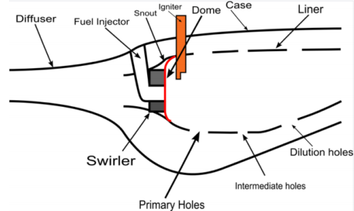
• Components of combustor: Fig. 1
1. Case: The shell of the combustor, located on the outermost layer, acts as protection.
2. Diffuser: The main function of the compressor is to provide the compressor chamber with appropriate speed and pressure to support the full combustion of fuel [4].
3. Liner: The air flow will finally be led into the combustion area under the action of the casing.
4. Snout: The primary air flow is separated from the secondary air flow mainly because of the nozzle, which is an extension of the dome [5].
5. Swirler/Dome: When the primary air enters the combustion area, the dome and cyclone, as part of the combustion chamber, can play a guiding role. Their role is to create turbulence in the air stream, allowing the air to mix quickly and fully with the atomized fuel [6].
6. Fuel injector: The injector IS responsible for atomizing the fuel (increasing the contact area between the fuel and the air to burn more fully) and introducing the fuel into the combustion zone [7].
7. Igniter: The fuel and air can be fully mixed thanks to the role of the igniter. Therefore, the igniter needs to be far enough upstream during operation, which can effectively prevent the igniter from burning out. Combustion occurs after the igniter is started, after which the combustion is self-sustaining, and the igniter no longer participates in the subsequent combustion, that is, the igniter only plays the role of providing flame [8].
|
Figure 1. Three types of ignition. |
Turbine
A turbine is a rotating power machine that extracts energy from flowing working fluid and converts it into useful mechanical work [11]. It acts like a fan, using exhaust gases to blow fuel vapor into the engine. The mechanical work generated by the turbine is mainly used to generate electricity, and the carrier of the generator is the combined generator [9]. A stationary blade and a rotor blade compose one stage of a turbine. Combusted high temperature and pressure gas comes out from nozzle of stationary blades and strikes on the rotor blades to rotate them.
There are two main types of turbines, classification according to airflow performance category:
1. Impulse turbine: It greatly changes the flow direction of the high speed gas jet and scatters in different directions. The resulting impact makes the turbine spin fast, reducing the kinetic energy of the fluid flow. The biggest feature of the gas in the rotor blade is that the working pressure does not change [10].
2. Reaction turbine: It produces torque by reacting with gas pressure. As the gas passes through the turbine rotor blades, the pressure changes dramatically [11].
Auxiliary Equipment [12].
Auxiliary equipment is used to boost the performance of gas turbine so that it can quick start or achieve a higher efficiency without large capital costs or high risks. Following with several examples:
• Air Oil Separator [13].
The sump ventilation is contaminated with oil mist, causing unwanted conditions when ventilated to environment. Air oil separator is newly designed to separate air and oil.
• Water Wash System [14].
By installing the water washing skid/system, the performance of the gas turbine can be effectively improved by 2% to 4% and its working performance can be improved. In addition, the continuous output of gas turbine can be ensured by formulating offline/online maintenance plan.
• Fuels Systems [15].
Advantages of the new gas/liquid fuel system:
1. “Up to date” fuel system
2. More optional fuel volumes
3. General improved reliability for fuel changeover from gas/liquid.
4. General improved start-up reliability.
• Lubrication System
The performance of gas turbines can be improved by using auxiliary equipment. This allows the gas turbine to start up faster and operate more efficiently without incurring large additional expenditures or exposing itself to considerable hazards. Here are some further examples [16]:
2.2. Current Status of Gas Turbine
Gas turbine has been widely used, and the composite device combining gas turbine with other heat engines has appeared. Gas turbines are widely used in power plants [17]. Gas turbine power plants use high temperature gas as the working medium. Gas turbine can effectively convert liquid and gas fuel into mechanical energy, and mechanical energy can convert electrical energy [18].
Advantage
• Direct output rotation motion.
• There is no need to warm up and there are not as many cold start problems, no need to add antifreeze and so on in cold weather areas.
• Various fuels can be used as fuel of gas turbine: gasoline, diesel, kerosene, peanut oil, and almost all flammable liquids, even mixed liquids.
Disadvantage
• Suitable for high speed stable operation situation, idle or acceleration efficiency is relatively much lower, and idle fuel consumption cost is very high [19].
• During operation, the temperature in the engine continues to be very high, and the high temperature resistance and durability of the material are high requirements, resulting in high price.
• The instantaneous response is not good.
• NOx emissions are exponentially related to temperature, so high temperature turbines have extremely high emissions, it is difficult to meet the environmental requirements.
2.3. Thermodynamic Brayton Cycle
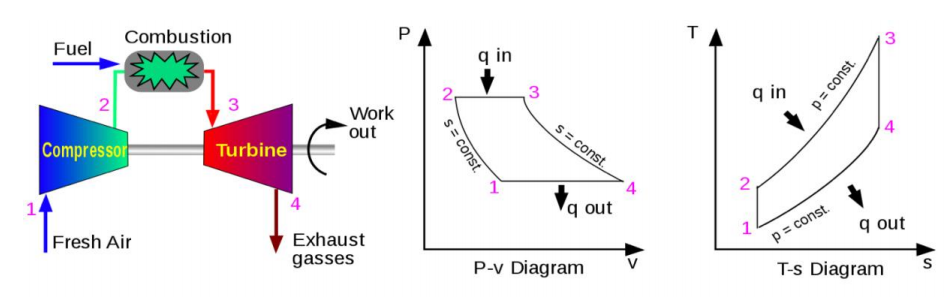
2.3.1. Ideal Brayton Cycle. 1. Isoentropic process-the ambient air is finally drawn into the compressor and then pressurized in the compressor.
2. Isobaric process-compressed air, pressurized fuel will then pass through the combustion chamber for combustion, which is a constant pressure process.
3. Isoentropic process-heated pressurized air, and a large amount of energy will be released from the burned fuel.
4. Isobaric process - heat removal (in atmosphere). Figure 2 shows three ignition types.
|
Figure 2. Three types of ignition. |
Thermal efficiency of Brayton cycle is:
(1) | ||
(2) | ||
(3) |
Thus
(4) |
whereis called the pressure ratio and is the specific heat ratio [16].
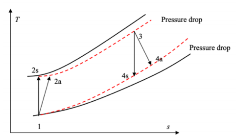
Because the compression process and expansion process are not isentropic processes, the actual Brayton cycle describes the real cycle process of gas turbine. In operation, the main reason for the decrease of working efficiency is the working temperature loss of compressor and expander.
2.3.2. Actual Brayton Cycle. 1. Adiabatic process-compression
2. Isobaric process- heat addition.
3. Adiabatic process-expansion.
4. Isobaric process-heat rejection. Figure 3 shows the actual Brighton cycle.
|
Figure 3. Actual Bryton cycle. |
Thermal efficiency of Actual Bryton cycle is:
(5) | ||
(6) |
3. Ceramic
3.1. The Advantages of Ceramic Materials
Metal materials are the most widely used materials in the world. However, the use of existing metal materials as current gas turbine materials will be subject to relatively strict temperature restrictions, which will not reach the ideal high temperature. Ceramic materials provide the best solution to this problem, and can significantly improve the shortcomings and drawbacks of gas turbines in work.
Ceramic materials can improve the working life and working characteristics of industrial gas turbines by:
1. The working temperature of non cooling ceramic components is increased by changing the turbine temperature, so as to improve the thermal efficiency and output power.
2. The use of non cooling ceramics to replace metal blades and blades can effectively avoid heat loss during work and improve engine performance.
3. Using ceramics to replace metal combustion chamber lining will allow operation at higher combustion chamber wall temperature.
4. Reduce the emission of NO and CO, also lead to fuel savings, so that the gas turbine is more environmentally friendly.
3.2. Design of Ceramic Components
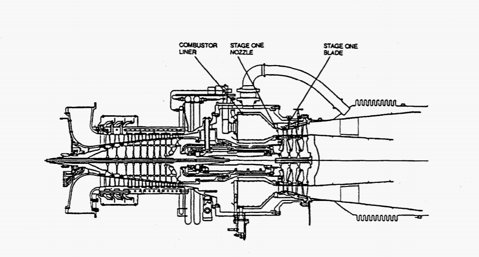
3.2.1. Design concept. The idea of replacing metal materials with ceramic materials is to redevelop the original materials as much as possible to minimize the cost, but also should minimize the ceramic or metal interface issues. The picture below is a sectional view of a gas turbine. It shows the three most important components: blade, nozzle and combustor liner, and indicates their position and shape: Fig. 4
|
Figure 4. Internal structure of stationary gas turbine. |
3.2.2. Ceramic Blade Design [18]. There are many design schemes for gas turbine, and each scheme will affect its working performance. The most typical design scheme is that the blade adopts dovetail design. After experimental verification, it is found that the dovetail design can effectively avoid the occurrence of resonance and improve the working performance of gas turbine. For the dovetail angle, the most ideal angle is 55 degrees.
|
Figure 5. The relationship between the dovetail angle and the coefficient of friction. |
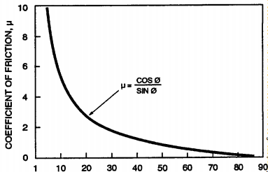
There is a unique relationship between dovetail angle and friction coefficient (Figure 5). The figure shows that there is a "critical" friction coefficient for any given angle. As long as the blade friction coefficient is kept under the curve of any corresponding angle, the blade accessories can slide radially outwards and inwards during the start/stop transient. Once this "critical" friction coefficient is reached, the blade cannot overcome the friction that allows it to move radially, and "extrusion" may occur between the ceramic blade and the metal disk. This kind of extrusion will produce high local stress, resulting in rapid fracture of ceramic blade. Therefore, a smaller angle is required, because there is less possibility of adhesion, thus forming a dovetail connection, and the ideal angle is 45 degrees.
Next is the compatibility layer. There are special performance requirements for the material properties of gas turbine. Neither too hard nor too soft. It must be ensured that the stress distribution of the load received in the working process is very uniform, otherwise the stress concentration is very likely to occur, leading to the reduction of the working life.
3.2.3. Ceramic Nozzle Design. Nozzle is an important part of gas turbine, and its design is very important. At present, the nozzle of gas turbine is mainly ceramic nozzle, and its role is mainly reflected in two aspects: the design of nozzle airfoil and the design of connection and seal. The nozzle design method and material property requirements are also very strict [19].
In this design, the biggest advantage is that the hook design principle is used. This design can effectively reduce the stress load to the minimum, effectively avoid the phenomenon of stress concentration, and maximize the use of space. In addition, it is necessary to pretreat the hook in the actual working process to prevent its strength from failing to meet the requirements and causing failure in the working process. The nozzle is connected mainly by pins, which can make good use of the mechanical link structure between them to improve the mechanical performance of the hook. Another important feature is that the nozzle is generally made of ceramic materials. Compared with the nozzle made of metal materials, the ceramic materials do not need seals to seal, which can effectively reduce the heat loss in the combustion chamber, thus indirectly improving the working efficiency of the gas turbine. In addition, because ceramic materials have the characteristics of high hardness and high temperature resistance, it can also effectively avoid the problem of material performance degradation caused by high temperature during the working process.
3.2.4. Combustor liner. There are many kinds of working materials for gas turbine. However, the hot wall ceramic materials play an important role in all materials, and have a very important influence on the working process of the combustion chamber. From the perspective of its working process, the main reasons are as follows:
When the outlet temperature of the combustion chamber is about 1200 °C and above, it is increasingly difficult to provide sufficient wall cooling airflow and ideal outlet radial gas temperature distribution because a larger proportion of the total airflow is required for premixing with fuel.
2. The ceramic hot wall will help to reduce the air-fuel ratio of lean flameout and reduce the CO emissions when approaching this limit.
3. The hot combustion chamber wall will help to adjust the outlet radial temperature curve, making it more suitable for the increase of the life of ceramic and metal turbine blades.
To ensure maximum stability and CO emissions, ceramic materials will be used in the most critical areas of the combustion chamber. The first concept is based on thin ceramic tiles supported by metal structures; The second type is integral gasket. Another design includes a full ring combustor made of continuous fiber reinforced ceramic matrix composites. These are the two most commonly used methods. Because their requirements and costs are different, they are used in different situations.
3.3. Materials Selection Strategy
Turbine engine performance can be significantly improved by using uncooled components and modestly increasing combustion temperatures. Through the experimental observation data, it can be found that compared with the previous materials, ceramic materials can reduce the stress concentration to the minimum, and can also effectively reduce the ambient temperature of the wall. This excellent working performance is of great significance to improve the working performance of gas turbine.
Table 1 shows the best materials for blades, nozzles and combustor liners of gas turbines. It can be seen from Table 1 that the nozzle can often be made of the following two materials: silicon nitride material (NT-154, Norton Advanced Ceramics; SN-88, NGK Insulator Co., Ltd.) and a silicon carbide material (Hexoloy ® SA, silicon carbide). This selection method is mainly determined by considering the particularity of the working place when the nozzle is working [20].
3.4. Life Predictions and Prolong
Reducing machine losses and prolonging the life of ceramic components are very important for stationary gas turbines [21].
• In the process of work, it is necessary to ensure that there are enough iterative calculations to minimize the stress value.
• The design stress and temperature shall meet the following conditions: it must be lower than the creep dominant state.
• For start-up and shutdown procedures, procedures that are compatible with industrial use and minimize transient stresses may be considered.
4. Conclusion
One of the most advantageous features is the reduced clamping load through the use of a “hook” attachment, which is necessary to connect the nozzle to the diaphragm. In principle, the aerodynamic load acting on the nozzle is sufficient to hold it in place. In practice, however, the nozzle needs to be preloaded to ensure that the nozzle remains on the diaphragm during all engine operations. Experiments and data show that the heat load is mainly responsible for the stress in the nozzle airfoil. According to the nozzle design, all tangential aerodynamic loads react through the chamfered surface on the nozzle hook, which is interfaced with the nozzle positioning pin. Another useful feature is the nozzle locator pin. Unlike the metal nozzles used in solar engines, ceramic nozzles do not use metal seals between adjacent nozzles. The seals on the metal nozzles serve a purpose.
References
[1]. Yun B, Ren X, Gang L. 2020 An Analysis of the Gaps between Moving and Stationary Parts of YL-type Flue Gas Turbine during Installation and Operation. Sino-Global Energy, 34: 39-42.
[2]. Price J, Jimenez O, Parthasarathy V. 2000 Ceramic Stationary Gas Turbine Development Program — Seventh Annual Summary. American Society of Mechanical Engineers, 20: 101-108.
[3]. Chen Y, Zhang H T. 2010 Flow Analysis of Stationary Blades for Floor Type Heavy Duty Gas Turbine Compressor. Turbine Technology, 20: 110-118.
[4]. Neidel A, Cagliyan E. 2013 Multiple Fractures of Used In-Service Disc Springs in a Stationary Gas Turbine Engine. Practical Metallography, 13(5): 50.
[5]. Liu Z, Shu X, Yang A. 2020 Selection of air pollutant emission standard limits for stationary gas turbines. China Power, 53(8): 8.
[6]. Xiao L, Zhang L, Li Y. 1993 Structural design of long-life power turbine for light gas turbine. Thermal Power Engineering, 8(6): 3-8.
[7]. Xu Y, Chen T, Zhang M. 2022 A removal process for the first stage moving blade of gas turbine compressor. Mechanical Engineering and Automation, 20(1): 30-41.
[8]. Zhang Y. 2020 Research on micro gas turbine speed control strategy. China University of Mining and Technology.
[9]. Michel K, Li T. 1982 Application of energy of pulse gas flow in gas turbine. Diesel Engine, 7(4): 29-33.
[10]. Guo L, Zhu L, Hou J, Wang H. 2019 Gas turbine NO_ Status quo and prospect of x control technology and catalyst application. Power Technology and Environmental Protection, 35 (1): 13-15.
[11]. Zhang J, Lang X, Yang J, Wang W, Wang D. 2020 Comparative Analysis of Domestic and Foreign Gas Turbine Emission Standards. Environmental Protection and Circular Economy, 40(9): 71-74.
[12]. Liu Z, Shu X, Yang A, Li Y. 2020 Selection of air pollutant emission standard limits for stationary gas turbines. China Power, 53(8): 117-124.
[13]. Wang J. 2011 Application of QD128 gas turbine generator set in super large IDC/EDC machine room. Posts and Telecommunications Design Technology, 7(6): 71-76.
[14]. Zhang W. 1984 Icing of gas turbine compressor and its impact on operation. Turbine Technology, 84(3): 30-41.
[15]. Wang S, Lv Y, Ye Q. 2022 Frost and blockage prevention technology of gas turbine air filter element. Petroleum Industry Technical Supervision, 38(9): 9-12.
[16]. Pan Z, Xue Z. 2022 Research and Practice of Fast Load Changing of Gas Turbine in Frequency Modulation Market. Gas Turbine Technology, 35(3): 12-18+48.
[17]. Jia X, Wu Y, Tang Z, Ji J. 2022 Development and application of gas turbine lubricating oil pump durability test bench. Gas Turbine Technology, 35(3): 54-57.
[18]. Wang W, Zhang Z, Hu Z. 2022 9E Logic Analysis and Fault Handling of Gas Turbine Blowing System. Gas Turbine Technology, 35(3): 62-65.
[19]. Duan X. 2022 Defect Analysis and Technical Transformation of Gas Turbine Combustible Gas Detection System. Gas Turbine Technology, 35(3): 66-69.
[20]. Liu S, He A, Guo S. 2022 Overview of Neural Network Based Gas Turbine Control and Modeling Technology. Thermal Turbines, 51(3): 155-160+169.
[21]. Xie Y, Wang Y, Shi D, Zhang D. 2022 Research Progress on Flow Thermosetting Characteristics of Heavy Gas Turbine Blades. Thermal Turbines, 51(3): 170-177+218.
Cite this article
Xia,Y. (2023). Analysis of the research status of stationary gas turbine and its material selection. Applied and Computational Engineering,5,481-490.
Data availability
The datasets used and/or analyzed during the current study will be available from the authors upon reasonable request.
Disclaimer/Publisher's Note
The statements, opinions and data contained in all publications are solely those of the individual author(s) and contributor(s) and not of EWA Publishing and/or the editor(s). EWA Publishing and/or the editor(s) disclaim responsibility for any injury to people or property resulting from any ideas, methods, instructions or products referred to in the content.
About volume
Volume title: Proceedings of the 3rd International Conference on Signal Processing and Machine Learning
© 2024 by the author(s). Licensee EWA Publishing, Oxford, UK. This article is an open access article distributed under the terms and
conditions of the Creative Commons Attribution (CC BY) license. Authors who
publish this series agree to the following terms:
1. Authors retain copyright and grant the series right of first publication with the work simultaneously licensed under a Creative Commons
Attribution License that allows others to share the work with an acknowledgment of the work's authorship and initial publication in this
series.
2. Authors are able to enter into separate, additional contractual arrangements for the non-exclusive distribution of the series's published
version of the work (e.g., post it to an institutional repository or publish it in a book), with an acknowledgment of its initial
publication in this series.
3. Authors are permitted and encouraged to post their work online (e.g., in institutional repositories or on their website) prior to and
during the submission process, as it can lead to productive exchanges, as well as earlier and greater citation of published work (See
Open access policy for details).
References
[1]. Yun B, Ren X, Gang L. 2020 An Analysis of the Gaps between Moving and Stationary Parts of YL-type Flue Gas Turbine during Installation and Operation. Sino-Global Energy, 34: 39-42.
[2]. Price J, Jimenez O, Parthasarathy V. 2000 Ceramic Stationary Gas Turbine Development Program — Seventh Annual Summary. American Society of Mechanical Engineers, 20: 101-108.
[3]. Chen Y, Zhang H T. 2010 Flow Analysis of Stationary Blades for Floor Type Heavy Duty Gas Turbine Compressor. Turbine Technology, 20: 110-118.
[4]. Neidel A, Cagliyan E. 2013 Multiple Fractures of Used In-Service Disc Springs in a Stationary Gas Turbine Engine. Practical Metallography, 13(5): 50.
[5]. Liu Z, Shu X, Yang A. 2020 Selection of air pollutant emission standard limits for stationary gas turbines. China Power, 53(8): 8.
[6]. Xiao L, Zhang L, Li Y. 1993 Structural design of long-life power turbine for light gas turbine. Thermal Power Engineering, 8(6): 3-8.
[7]. Xu Y, Chen T, Zhang M. 2022 A removal process for the first stage moving blade of gas turbine compressor. Mechanical Engineering and Automation, 20(1): 30-41.
[8]. Zhang Y. 2020 Research on micro gas turbine speed control strategy. China University of Mining and Technology.
[9]. Michel K, Li T. 1982 Application of energy of pulse gas flow in gas turbine. Diesel Engine, 7(4): 29-33.
[10]. Guo L, Zhu L, Hou J, Wang H. 2019 Gas turbine NO_ Status quo and prospect of x control technology and catalyst application. Power Technology and Environmental Protection, 35 (1): 13-15.
[11]. Zhang J, Lang X, Yang J, Wang W, Wang D. 2020 Comparative Analysis of Domestic and Foreign Gas Turbine Emission Standards. Environmental Protection and Circular Economy, 40(9): 71-74.
[12]. Liu Z, Shu X, Yang A, Li Y. 2020 Selection of air pollutant emission standard limits for stationary gas turbines. China Power, 53(8): 117-124.
[13]. Wang J. 2011 Application of QD128 gas turbine generator set in super large IDC/EDC machine room. Posts and Telecommunications Design Technology, 7(6): 71-76.
[14]. Zhang W. 1984 Icing of gas turbine compressor and its impact on operation. Turbine Technology, 84(3): 30-41.
[15]. Wang S, Lv Y, Ye Q. 2022 Frost and blockage prevention technology of gas turbine air filter element. Petroleum Industry Technical Supervision, 38(9): 9-12.
[16]. Pan Z, Xue Z. 2022 Research and Practice of Fast Load Changing of Gas Turbine in Frequency Modulation Market. Gas Turbine Technology, 35(3): 12-18+48.
[17]. Jia X, Wu Y, Tang Z, Ji J. 2022 Development and application of gas turbine lubricating oil pump durability test bench. Gas Turbine Technology, 35(3): 54-57.
[18]. Wang W, Zhang Z, Hu Z. 2022 9E Logic Analysis and Fault Handling of Gas Turbine Blowing System. Gas Turbine Technology, 35(3): 62-65.
[19]. Duan X. 2022 Defect Analysis and Technical Transformation of Gas Turbine Combustible Gas Detection System. Gas Turbine Technology, 35(3): 66-69.
[20]. Liu S, He A, Guo S. 2022 Overview of Neural Network Based Gas Turbine Control and Modeling Technology. Thermal Turbines, 51(3): 155-160+169.
[21]. Xie Y, Wang Y, Shi D, Zhang D. 2022 Research Progress on Flow Thermosetting Characteristics of Heavy Gas Turbine Blades. Thermal Turbines, 51(3): 170-177+218.