


1. Introduction
Due to fuel vehicles producing huge amounts of carbon dioxide emissions that contribute to global warming, and also the fact that oil is a scarce resource, which leads to fluctuating prices and causes source uncertainty. These problems were then addressed by the governments through policies and restrictions, which led to a global shift toward new energy applications. With all the different types of new energy applications, electric vehicles are gradually becoming the dominant direction in this field due to mature technology and a decrease in the cost of production [1]. The result suggests the requirement for a high-performance battery has also increased. This includes high energy intensity, which ensures a longer driving distance and lighter weight of the vehicles; safety, which prevents battery fire and explosion; and finally, affordability with improvement in advanced technology or materials.
The lithium battery is one of the ideal batteries with the advantage of high energy density, high operating voltage, long cycle life, and the absence of memory effect. Allowing it to become the most rapidly developing energy storage technologies [2]. However, higher capacity is always a target to overcome. Thus, new electrode materials with higher capacity become particularly significant. Currently, graphite is one of the most widely used materials for the anode material in lithium batteries. This is because it has a great balance between cost, power density, and stability due to its unique layered structure, which provides an efficient electron transport within the anode [3]. However, its capacity is considered a limitation when compared with new emerging materials, despite having a theoretical capacity of 372 mAh/g.
Among all the different potential anode materials, silicon was considered a suitable substitute for graphite for anode material. Its theoretical capacity is 4200 mAh/g (about ten times larger than graphite) with a low working voltage (0.37V vs Li/
Overall, this study focuses on current strategies with three different types of nanocoated silicon materials as anode material for lithium batteries in new energy vehicles. This includes Si-C, Si-metal oxide, and Si-polymer, which all have advantages and disadvantages in comparison. Therefore, this study will also provide an analysis and solution for those nanocoated silicon materials. Lastly, this study has a structure that is organised as follows: introduction, case description, problem analysis, suggestion, and conclusion.
2. Case description
To overcome the problem of silicon as an anode material in lithium batteries, researchers have developed different strategies by combining carbon with nanocoating, which includes carbon material, metal oxide, and polymer.
Among the three different material nanocoatings, the most widely used are carbon materials due to their mechanical flexibility and high electrical conductivity. A conductive network forms when amorphous carbon, graphene, or carbon nanotubes are coated onto nano-silicon particles, which improves electron transport. The carbon layer can also act as a buffer when silicon experiences volume expansion to nearly 300%. Specific designs, such as core–shell or yolk–shell architectures, create internal voids between the silicon core and the carbon shell. These voids absorb all of the expansion of silicon; as a result, electrodes do not then pulverise, and this has improved cycling stability in lithium batteries.
Furthermore, metal oxide coatings like TiO₂, Fe₂O₃, or Al₂O₃ are mechanically rigid and thermally stable. These coatings work as a physical barriers that can separate silicon from the electrolyte. These barriers reduce undesired reactions like continuous growth of the solid electrolyte interphase, which will consume electrolyte and lithium, leading to a decrease in battery capacity. Unlike carbon, certain metal oxides, mainly amorphous TiO₂, do not stretch like carbon when lithiation. Therefore, it has a stable structure for long charging cycles and doesn’t collapse easily.
Lastly, polymeric coatings are considered multifunctional. Bio-derived polymers such as sodium alginate or chitosan create strong chemical bonds with hydroxyl groups that are on the silicon surface in order to improve adhesion, which prevents falling apart or detachment during charging cycling. These polymers are flexible and elastic in order to reduce volume changes as well. Conductive polymers such as polyaniline or PANI bind with silicon and form a three-dimensional network, which helps electrons move quickly through the electrode; therefore, this improves the conductivity of the whole battery. In addition, conductive polymers don’t require as much space as carbon or other conductive materials, which makes more room for silicon. As a result, the battery will have a higher energy density but also better cycling life and mechanical strength.
3. Analysis and challenge
3.1. Carbon coated Si anode (Si-C)
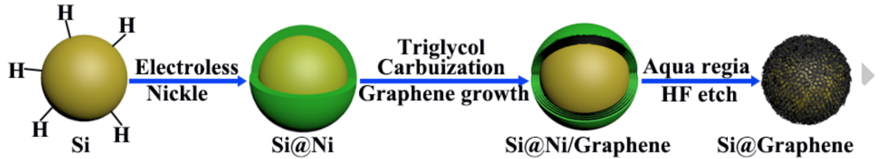
In order to produce Si-C, the coating process used the method of nickel as a catalyst, which is demonstrated below [9]: Initially, the oxide layer on the silicon had to be removed. This could be done by dispersing 0.5g of silicon nanoparticles in a mixed solution containing hydrofluoric acid (65 mL), deionised water (50 mL), and ethanol (35 mL). Subsequently, an electroless plating solution was then prepared by mixing 0.1 molL-1 NiCl2·6H2O, 0.56 molL-1 NH4Cl, 0.03 molL-1 C6H8O7, 0.3 molL-1 NaH2PO2 and 0.01 molL-1 C12H25O4NaS. The NH3•H2O was added into the electroless plating solution drop by drop until the pH was adjusted to 8.5. Thereafter, the treated Si nanoparticles were added into the electroless plating solution at 50°C for 10 minutes, the aim is to reduce Ni²⁺ to metallic Ni directly on the Si surface by the reducing agent in the bath (NaH2PO2). This forms a uniform nickel layer around silicon, and these nickel-coated silicon particles were then dispersed into a mixed solution containing 38 ml triethylene glycol and 0.25 ml NaOH aqueous solution (Wt.NaOH=50wt.%) and then stirred at 185ºC for 14 hour. Lastly, it was washed with deionised water and dried overnight to obtain the carbon-incorporated Ni-coated Si particles. This is followed by heating under Ar at 450 °C for 1 hour to form a graphene coating layer. To remove the nickel coating layer, it was treated by the mixture solution of HNO3, HCl, and HF etching for several hours, and the Si-C is finally obtained. This process is further displayed in Figure 1 below.
The Si-C had the advantages of high reversible capacity by retaining 1909 mAh/g after 100 cycles at 0.2 A/g. This meant that the battery could store more charge, which gave a longer run time per charge. Furthermore, pure silicon degraded from 3612 mAh/g to 865 mAh/g over 100 cycles, which showed that Si-C had a better battery stability over the long term. The reason was that pure silicon lost most of its capacity due to expansion and contraction (about 300%), whereas Si-C acted as a flexible material, which had a smaller expansion (about 160%) and gave less mechanical stress and therefore longer life. On the other hand, it also delivered 975 mAh/g at a high current density of 5 A/g. This highlighted its excellent conductivity and, therefore, higher charge and discharge speed. In comparison, pure silicon only had 86 mAh/g at 5 A/g. In addition, Si-C had a lower charge transfer resistance (Rct), from 55.37 Ω (30th cycles) to 203.70 Ω (50th cycles), whereas pure silicon increased from 234.80 Ω (30th cycles) to 576.80 Ω (50th cycles). This improved electron and lithium ion conductivity, allowing them to move faster between the electrode and electrolyte.
Despite its advantages, Si-C is still experiencing a large expansion (about 160%) compared to the normal graphite anode (about 10%) during lithiation [10]. Over hundreds of cycles, this issue can be magnified, where there will be microcracks in the coating and exposure to the silicon, which will further increase cracking and pulverisation. The battery then holds less and less charge over time and eventually becomes unusable.
3.2. Metal oxides coated Si anode (Si-metal oxides)
On the other hand, Si-metal oxides can be produced by the method below [11]: In the beginning, 0.6 g of hydroxypropyl cellulose (HPC, Mw 100,000, Aldrich) was dissolved in ethanol. 1.0 g of silicon powder (crystalline, APS 0.05–0.10 µm, 98%) was then added to the HPC/ethanol and dispersed by an ultrasonicator in a dry room for 10 min. Then add 5.25 ml of titanium isopropoxide (Ti[OCH(CH3)2]4), with a purity of 97% (obtained from Aldrich), to the solution. This is followed by the addition of ammonia solution, until the pH values reach 9.66, 10.14, 10.48, 10.70 and 11.08 were attained. This mixed solution was stirred for 160 min and then aged at 80 ◦C for 4 hours. This allows a TiO₂ gel layer to form around the silicon. And finally, the product was filtered through a filter paper, and the TiO₂ nanocoated silicon obtained was washed with deionised water and dried at 25 ◦C for 7 days.
The TiO₂ nanocoated silicon had the advantages of stable discharge capacity. The coating layer acted as a buffer layer to reduce the volume expansion of silicon. This was demonstrated in Figure 3, where the TiO₂ nanocoated silicon at pH 10.7 performed a more stable discharge capacity compared to pure silicon over many cycles. This allowed it to have a longer life due to a reduction in volume expansion. Moreover, the TiO₂ layer acted as a protective physical layer that separated the silicon surface and electrolyte. This reduced unwanted reactions between silicon and electrolyte. These unwanted reactions could form an unstable solid electrolyte interphase (SEI), which consumes electrolyte and lithium. The TiO₂ layer could maintain a stable SEI, which improved cycle life and increased the efficiency of the battery. Besides this, the TiO₂ layer also controlled how lithium ions moved in and out of the silicon. As the TiO₂ layer contained nano-pores with diameters of 6.9–9.2 nm, these pores allowed lithium ions to move at a controlled rate, which could prevent rapid lithium ion diffusion, causing uneven lithiation, which would expand silicon too quickly and lead to cracking and pulverisation. As a result, TiO₂ nanocoated silicon had lower lithium ion diffusivity (2.4 × 10⁻¹²–5.7 × 10⁻¹³ cm²/s) than pure silicon (4.3 × 10⁻¹² cm²/s) [11].
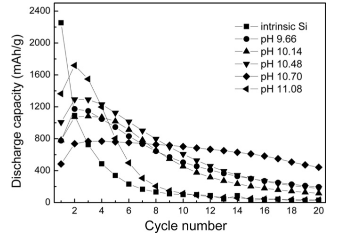
However, there are still disadvantages when TiO₂ work as a protective barrier. As it blocks some of the lithium ions during the first charging cycle, this leads to a lower initial capacity, which is much lower than pure silicon and Si-C. This is also demonstrated in Figure 2. Furthermore, while the coating layer controls the speed of lithium ions, it also slows down their movement, resulting in slow charge and discharge speeds, which becomes a major issue as the current demand for fast charging increases. The balance between cycling stability and charging performance should be taken into consideration. Lastly, this studies only focus on TiO₂ as the metal oxide material; there are also different materials, such as Fe₂O₃, or Al₂O₃ might have a better performance and fewer limitations.
3.3. Polymer composite coated Si anode (Si-polymer)
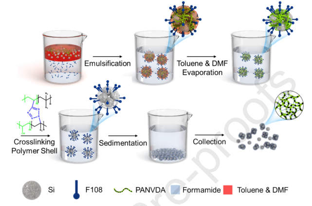
Lastly, Si-polymer can be produced by the steps below [12]: The silicon nanoparticles with cross-linked PAN (Si NPs@x-PAN) are being used as an example in this case. In the first place, 0.2 g PANVDA was dissolved in 20 g DMF, and 0.4 g silicon NPs were dispersed in another organic solvent, toluene. Then, the Si NP/polymer suspension was prepared by mixing these two solutions. The surfactant solution was prepared by dissolving 22.6 g F108 surfactant in 400 mL of formamide. After that, the Si NP/polymer suspension was poured into the surfactant solution in a 1:10 volume ratio (NP/polymer suspension: surfactant solution), then stirred vigorously with a homogeniser at 12,000 rpm for 2 minutes to create a nonaqueous emulsion with droplets containing Si NPs and PANVDA. The emulsion was stirred at 70 °C for 2 days to evaporate DMF and toluene, allowing the polymer to coat the nanoparticles. The suspension was then purged with argon and heated at 130 °C for 2 hours to thermally crosslink the PANVDA coating. The resulting Si NPs@x-PAN composite clusters were collected by centrifugation, washed repeatedly with ethanol to remove residual surfactant and impurities, and finally dried at 80 °C for 1 day in a vacuum oven, yielding the final coated nanoparticles. The process of synthesis of Si NPs@x-PAN is demonstrated in Figure 3.
The Si-polymer had the unique advantages of high areal and specific capacity. This allowed the anode to store more charge both per unit surface area (about 2 mAh/cm²) and per unit weight (about 2000 mAh/g), making it different compared to other nanocoated silicon materials, as lots of coatings reduced capacity significantly. Moreover, Si-polymer also had the advantage of long-term cycle stability, as research showed that after 100 charging cycles, the capacity only dropped 5% and after 1000 charging cycles, it still retained more than 75% at a moderate current (0.5 C). Even when charged at an extremely high current (50 C), its capacity still retained 1880 mAh/g, which was about 89.2% of its original capacity (2109 mAh/g). This highlighted the ability not only of large capacity but also of its fast-charging advantages. This was mainly because its 3 nm thick PAN coating directed lithium ion evenly into silicon, which helped silicon expand uniformly in all directions (isotropic volume expansion), which reduced the mechanical stress [12].
Nevertheless, Si-polymer still suffers from SEI formation in the first cycles. Where its initial coulombic efficiency (ICE) is 86.4% compared to a graphite ICE value larger than 90%. This means that large amounts of lithium ions are irreversibly consumed to form SEI and are no longer available for battery operation, which reduces the total capacity in the first place. Furthermore, Si-polymer has a complex synthesis process, as it has three polymer stages from PANVDC to PANVDA to x-Pan, which might have scalability concerns, where it could be expensive and time-consuming.
4. Summary and suggestions
|
Type |
Advantages |
Disadvantages |
|
Si-C |
-high reversible capacity -excellent battery stability -small expansion compared to pure silicon -excellent conductivity |
-large expansion compared to normal graphite |
|
Si-metal oxide |
-stable discharge capacity -prevent SEI from forming -prevent rapid lithium ion diffusion |
-trade-off between cycling stability and charging performance |
|
Si-polymer |
-high areal and specific capacity -long-term cycle stability |
-SEI formation -complex synthesis process |
From Table 1, it is obvious that all different types of nanocoated silicon anode material have the advantage of stable cycles in different levels, which has surpassed the original pure silicon anode material by far, as the coated silicon provides a buffer layer to reduce mechanical stress from volume expansion in different ways. This suggests that those three types of nanocoated silicon can be used in the long term with a long cycle life. Apart from this, Si-C has the advantage of excellent conductivity, highlighting a fast charging speed which fulfils the current demand as people universally pursue convenience and efficiency in life and technology. In comparison to fuel vehicles, which don’t have the concern of charging, fast charging reduces consumers' worries. Si-metal oxide , on the other hand, has good prevention of SEI forming, which reduces the amount of lithium loss, further enhancing the stability of the battery. Si-polymer has the largest charge capacity among the three different materials. Even when silicon anodes are coated with other materials, the capacity will drop significantly due to less silicon being available to react with lithium ions during charging and discharging. Overall, these advantages make nanocoated silicon have the potential to become a substitute for conventional graphite and pure silicon anode material, as graphite has the limitation of low capacity and silicon has the disadvantage of large volume expansion and short cycle life, which makes the nanocoated silicon anode ideal for future battery applications.
However, the nanocoated silicon anodes still have problems to tackle. Si-C has the disadvantage of a large expansion compared to normal graphite anode material. As a solution, porous silicon can be used, where silicon expands into empty space instead of exerting stress on the carbon layer. This might allow the expansion of Si-C to decrease closer to graphite material while retaining its capacity. On the other hand, Si-oxide has the trade-off problem between cycling stability and charging performance. This could be solved by combining a conductive material that maintains silicon’s excellent conductivity. Moreover, Si-polymer has the major problem of a complex synthesis process, making it harder to become scalable for production at low cost. As an approach, the main production could focus on PANVDC and PANVDA with a simpler synthesis process. They both have a slightly lower quality than x-Pan, but have a lower cost to meet the demand for anode materials. As a result, the advantages of nanocoated silicon have outweighed its disadvantages.
To determine which nanocoated silicon is the most suitable for the current lithium anode material, it will depend on which specific characteristics are prioritised. In particular, different electric vehicle companies focus on different directions. Si-C gives the advantage of fast charging but still suffers from large expansion. Si-metal oxide has strong cycling stability but has a relatively poor conductivity. Si-polymer has one of the largest capacities, but the complex synthesis process remains a problem. Among different nanocoated silicon anodes, Si-C is the most realistic choice today, as it has already been tested and adopted by battery companies; its synthesis process is relatively mature and scalable compared with other nanocoated silicon materials. Although it doesn’t completely solve the problem of large expansion, it provides sufficient improvement compared to pure silicon. On the other hand, in the next five or ten years, Si-polymer has great potential. This is because Si-polymer has the best balance between all factors. After simplifying the synthesis process, it could also be produced at scale and lower cost, becoming the dominant anode material. Si-metal oxides, unfortunately, are limited by the trade-off. This causes it to become less competitive compared to other nanocoated materials; if there are no solutions, it might even be phased out.
In the future, these nanocoated silicon anodes could be produced in large quantities and replace graphite in the next generation of lithium-ion batteries. Especially supported by government subsidies, lots of firms can further improve the nanocoated battery’s properties. For instance, one of the directions could be involving multilayer coatings, meeting the optimal ability demand by balancing factors between charge capacity, stability, and conductivity.
5. Conclusion
This study investigates the application of nanocoated silicon materials in a lithium battery anode. This includes Si-C, Si-metal oxide and Si-polymer, which have demonstrated great potential to become a substitute for the current anode material graphite with the key disadvantage of low charge capacity. On the other hand, these nanocoated silicon also mitigates the drawback of pure silicon’s poor cycling stability and conductivity while retaining as much of its charge capacity as possible. This nanocoated silicon has then become the main direction in future battery development.
The study also presents the method to produce each nanocoated silicon material in detail and evaluates its advantages and disadvantages. This is when they all have a common advantage of stable cycles. Specifically, Si-C has the advantage of excellent conductivity, Si-metal oxide demonstrates a good prevention of SEI formation, and Si-polymer presents its largest charge capacity among the three different nanocoated silicon. However, each of the nanocoated silicon materials has its drawbacks. For instance, Si-C has the disadvantage of a large expansion compared to normal graphite anode material, Si-metal oxide has a trade-off between cycling stability and charging performance, and Si-polymer suffers from a complex synthesis process. These issues require further research and development to overcome, in order to be widely used in practical applications.
Currently, Si-C has become the most commercially viable option due to its mature synthesis process and its overall sufficient factors to meet the demand. Si-metal oxide is plagued by the trade-off between two essential factors, making it unlikely to make significant breakthroughs in the future. Si-polymer, on the other hand, has the most potential for the future if the synthesis process is simplified, because it offers the best balance among all factors and maximally retains the benefits of pure silicon. As a result, having the most favourable conditions will increase its competitiveness. Over time, better research will overcome previous problems. However, at present, nanocoated silicon as a lithium battery anode material holds the most promising future.
References
[1]. Muratori, M., Alexander, M., Arent, D., Bazilian, M., Cazzola, P., Dede, E. M., Farrell, J., Gearhart, C., Greene, D., Jenn, A., Keyser, M., Lipman, T., Narumanchi, S., Pesaran, A., Sioshansi, R., Suomalainen, E., Tal, G., Walkowicz, K., & Ward, J. (2021). The rise of electric vehicles—2020 status and future expectations. Progress in Energy, 3(2), 022002.
[2]. Tarascon, J.-M. ., & Armand, M. (2001). Issues and challenges facing rechargeable lithium batteries. Nature, 414(6861), 359–367.
[3]. Zhang, H., Yang, Y., Ren, D., Wang, L., & He, X. (2021). Graphite as anode materials: Fundamental mechanism, recent progress and advances. Energy Storage Materials, 36, 147–170. https: //doi.org/10.1016/j.ensm.2020.12.027
[4]. Dong, H., Wang, J., Ding, H., Zong, F., Wang, P., Song, R., Zhang, N., Cui, X., Cui, X., & Li, S. (2022). Exploring the practical applications of silicon anodes: a review of silicon-based composites for lithium-ion batteries. Ionics, 28(7), 3057–3077. https: //doi.org/10.1007/s11581-022-04622-3
[5]. Wu, H., & Cui, Y. (2012). Designing nanostructured Si anodes for high energy lithium ion batteries. Nano Today, 7(5), 414–429. https: //doi.org/10.1016/j.nantod.2012.08.004
[6]. Hwa, Y., Park, C.-M., & Sohn, H.-J. (2012). Modified SiO as a high performance anode for Li-ion batteries. Journal of Power Sources, 222, 129–134. https: //doi.org/10.1016/j.jpowsour.2012.08.060
[7]. Fu, R., Ji, J., Yun, L., Jiang, Y., Zhang, J., Zhou, X., & Liu, Z. (2020). Graphene wrapped silicon suboxides anodes with suppressed Li-uptake behavior enabled superior cycling stability. Energy Storage Materials, 35, 317–326. https: //doi.org/10.1016/j.ensm.2020.11.027
[8]. Xu, Q., Sun, J., Li, J., Yin, Y., & Guo, Y. (2018). Scalable synthesis of spherical Si/C granules with 3D conducting networks as ultrahigh loading anodes in lithium-ion batteries. Energy Storage Materials, 12, 54–60. https: //doi.org/10.1016/j.ensm.2017.11.015
[9]. Wang, M., Wang, G., Wang, S., Zhang, J., Wang, J., Zhong, W., Fan, T.-Y., Yang, Z., Zheng, J., & Li, X. (2019). In situ catalytic growth 3D multi-layers graphene sheets coated nano-silicon anode for high performance lithium-ion batteries. Chemical Engineering Journal, 356, 895–903. https: //doi.org/10.1016/j.cej.2018.09.110
[10]. Xu, Z., Shi, X., Zhuang, X., Wang, Z., Sun, S., Li, K., & Zhang, T. (2021). Chemical Strain of Graphite-Based Anode during Lithiation and Delithiation at Various Temperatures. Research, 2021. https: //doi.org/10.34133/2021/9842391
[11]. Jeon, B. J., & Lee, J. K. (2011). Electrochemical characteristics of porous TiO2 encapsulated silicon anode. Electrochimica Acta, 56(18), 6261–6265. https: //doi.org/10.1016/j.electacta.2011.05.056
[12]. Jeong Hoon Yoon, Lee, G., Li, P., Baik, H., Yi, G.-R., & Jong Hyeok Park. (2022). Expandable crosslinked polymer coatings on silicon nanoparticle anode toward high-rate and long-cycle-life lithium-ion battery. Applied Surface Science, 571, 151294–151294. https: //doi.org/10.1016/j.apsusc.2021.151294
Cite this article
Wang,S.U. (2025). Application of Nanocoated Silicon-Based Materials in Lithium-Ion Battery Anodes. Applied and Computational Engineering,186,156-164.
Data availability
The datasets used and/or analyzed during the current study will be available from the authors upon reasonable request.
Disclaimer/Publisher's Note
The statements, opinions and data contained in all publications are solely those of the individual author(s) and contributor(s) and not of EWA Publishing and/or the editor(s). EWA Publishing and/or the editor(s) disclaim responsibility for any injury to people or property resulting from any ideas, methods, instructions or products referred to in the content.
About volume
Volume title: Proceedings of CONF-FMCE 2025 Symposium: Semantic Communication for Media Compression and Transmission
© 2024 by the author(s). Licensee EWA Publishing, Oxford, UK. This article is an open access article distributed under the terms and
conditions of the Creative Commons Attribution (CC BY) license. Authors who
publish this series agree to the following terms:
1. Authors retain copyright and grant the series right of first publication with the work simultaneously licensed under a Creative Commons
Attribution License that allows others to share the work with an acknowledgment of the work's authorship and initial publication in this
series.
2. Authors are able to enter into separate, additional contractual arrangements for the non-exclusive distribution of the series's published
version of the work (e.g., post it to an institutional repository or publish it in a book), with an acknowledgment of its initial
publication in this series.
3. Authors are permitted and encouraged to post their work online (e.g., in institutional repositories or on their website) prior to and
during the submission process, as it can lead to productive exchanges, as well as earlier and greater citation of published work (See
Open access policy for details).
References
[1]. Muratori, M., Alexander, M., Arent, D., Bazilian, M., Cazzola, P., Dede, E. M., Farrell, J., Gearhart, C., Greene, D., Jenn, A., Keyser, M., Lipman, T., Narumanchi, S., Pesaran, A., Sioshansi, R., Suomalainen, E., Tal, G., Walkowicz, K., & Ward, J. (2021). The rise of electric vehicles—2020 status and future expectations. Progress in Energy, 3(2), 022002.
[2]. Tarascon, J.-M. ., & Armand, M. (2001). Issues and challenges facing rechargeable lithium batteries. Nature, 414(6861), 359–367.
[3]. Zhang, H., Yang, Y., Ren, D., Wang, L., & He, X. (2021). Graphite as anode materials: Fundamental mechanism, recent progress and advances. Energy Storage Materials, 36, 147–170. https: //doi.org/10.1016/j.ensm.2020.12.027
[4]. Dong, H., Wang, J., Ding, H., Zong, F., Wang, P., Song, R., Zhang, N., Cui, X., Cui, X., & Li, S. (2022). Exploring the practical applications of silicon anodes: a review of silicon-based composites for lithium-ion batteries. Ionics, 28(7), 3057–3077. https: //doi.org/10.1007/s11581-022-04622-3
[5]. Wu, H., & Cui, Y. (2012). Designing nanostructured Si anodes for high energy lithium ion batteries. Nano Today, 7(5), 414–429. https: //doi.org/10.1016/j.nantod.2012.08.004
[6]. Hwa, Y., Park, C.-M., & Sohn, H.-J. (2012). Modified SiO as a high performance anode for Li-ion batteries. Journal of Power Sources, 222, 129–134. https: //doi.org/10.1016/j.jpowsour.2012.08.060
[7]. Fu, R., Ji, J., Yun, L., Jiang, Y., Zhang, J., Zhou, X., & Liu, Z. (2020). Graphene wrapped silicon suboxides anodes with suppressed Li-uptake behavior enabled superior cycling stability. Energy Storage Materials, 35, 317–326. https: //doi.org/10.1016/j.ensm.2020.11.027
[8]. Xu, Q., Sun, J., Li, J., Yin, Y., & Guo, Y. (2018). Scalable synthesis of spherical Si/C granules with 3D conducting networks as ultrahigh loading anodes in lithium-ion batteries. Energy Storage Materials, 12, 54–60. https: //doi.org/10.1016/j.ensm.2017.11.015
[9]. Wang, M., Wang, G., Wang, S., Zhang, J., Wang, J., Zhong, W., Fan, T.-Y., Yang, Z., Zheng, J., & Li, X. (2019). In situ catalytic growth 3D multi-layers graphene sheets coated nano-silicon anode for high performance lithium-ion batteries. Chemical Engineering Journal, 356, 895–903. https: //doi.org/10.1016/j.cej.2018.09.110
[10]. Xu, Z., Shi, X., Zhuang, X., Wang, Z., Sun, S., Li, K., & Zhang, T. (2021). Chemical Strain of Graphite-Based Anode during Lithiation and Delithiation at Various Temperatures. Research, 2021. https: //doi.org/10.34133/2021/9842391
[11]. Jeon, B. J., & Lee, J. K. (2011). Electrochemical characteristics of porous TiO2 encapsulated silicon anode. Electrochimica Acta, 56(18), 6261–6265. https: //doi.org/10.1016/j.electacta.2011.05.056
[12]. Jeong Hoon Yoon, Lee, G., Li, P., Baik, H., Yi, G.-R., & Jong Hyeok Park. (2022). Expandable crosslinked polymer coatings on silicon nanoparticle anode toward high-rate and long-cycle-life lithium-ion battery. Applied Surface Science, 571, 151294–151294. https: //doi.org/10.1016/j.apsusc.2021.151294