


1. Introduction
Currently, the fuselage and wing structures of classic hang gliders are fixed. This results in not only inconsistent maneuverability during low-speed take-off and cruise flight, but also some inconvenience in transportation. In general, a structure has no internal movement or relative motion among its members. Deployable Structures [1] or motion structures [2] are different. Their geometry can be altered to meet certain requirements. Based on the mobility of a mechanism [2], we investigated the theoretical feasibility of applying connecting rod mechanisms to the fuselage and wings. The flap wing is supposed to significantly enhance the consistency at handling at different speed to improve the safety. The foldable fuselage makes transportation and carrying more convenient.
Deployable mechanisms, such as umbrella-like deployable mechanisms, can unfold and retract their configurations according to changes in their working states. Many aircraft, such as aerospace equipment, cannot enter space in their fully deployed working state, so deployable mechanisms are widely applied. Wang X et al. [3] proposed a new umbrella-like deployable mechanism with the planar four-bar crank-slider mechanism as the deployment unit. They determined the angle and proportion of the model, simulated the movement process, and verified the effectiveness of the model's deployment and folding processes. Zhang J et al. [4] took the position and attitude of the wing folding and unfolding of flapping-wing aircraft as the design goal, and based on the mechanism combination design method, designed a transient folding-unfolding mechanism composed of slider linkage, spherical linkage and spatial linkage.
Establishing multi-level and multi-stage models is necessary for the design of mechanical structures of insect-inspired foldable wings. Insect wings, such as the zig-zag folding mechanism of dragonfly wings, are a multi-level structure [5]. Truong Q-T et al. [6] designed a foldable wing with a four-bar linkage mechanism modeled after insects to achieve the retraction and folding of the wing. The folding process of this bionic foldable wing is relatively simple and stable. Zhao Z F et al. [7] designed a flapping wing structure based on a four-bar linkage mechanism. They determined the output angle of the linkage mechanism according to the movement range of the bird joint angles, enabling it to move within the desired range.
2. Construction and geometrical dimensions of specimens
2.1. Design 1
The main structure of the glider is folded using the principle of a parallelogram mechanism, while the change in the elevation angle is achieved by flaps composed of a four-bar linkage mechanism (we named this model No.1), as shown in Figure 1. Origami and graphical methods [1] can be used to better understand the folding of a mechanical structure.
The dimensional synthesis of the four-bar mechanism for path generation can be achieved through two theories: relative angular motion analysis and the link geometry parameterization with Cartesian coordinates [8].

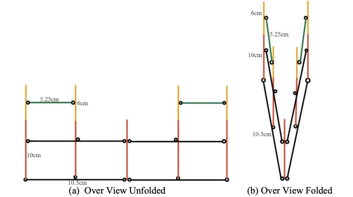
Describe the deployable structures using a topology diagram [9]. In Figure 2, the geometrical dimensions of the parallelogram mechanism of the glider (shown in Figure 1) are presented for both the unfolded state and the folded state.
The fold ratio [10] quantifies the ratio between the area of the unfolded and folded wings, and it is a key factor in evaluating the maneuverability of foldable wings. We have achieved an extremely high fold ratio in our design. This means the wings can be more compact when folded, while ensuring sufficient aerodynamic area when unfolded, which is highly valuable for enhancing the storage convenience and flight performance of the equipment.
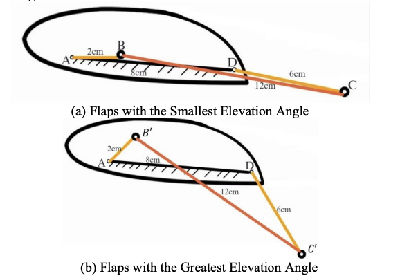
In Figure 3, the geometrical dimensions of the 4-bar Linkage Mechanism of the glider (shown in Figure 1) are presented for both the smallest elevation angle state and the greatest elevation angle state. The primary feathers of birds can rotate independently, serving as the main source of thrust [11], which generates flight during the flapping downstroke. Our four-bar linkage design helps provide lift by creating a bird-like wing structure.
2.2. Design 2
In Figure 4, this is the right part of main design diagram of our folding glider (The left half is a mirror image of the right half) which have two umbrella’s like elements (one is above MF and one is under MF). Slider CE and GI are able to move up and down while slider F could move left and right. AB is part of the wing which is related to main structure.

Slider F is regarded as a driver. If we pull it to the right, slider CE will come down while slider GI will rise up so that IJ and AB are tend to be perpendicular to MF and parallel to bar AK which means the glider is folded.
The extra part of the wing is demonstrated (Fig.5 The extra part of the wing). Point C of bar BC is connected with the slider and two pink lines are spring. One layer of design 1. can be installed on each connecting rod.

Because of the springs, BC and BD (also BD and CE) tend to get close to each other. As shown in Figure 6, when the slider goes down, springs are released so that BC and BD, BD and CE get close to each other which means that the wing is folded.

3. Test results and discussions
3.1. Design 1: parameter analysis
(a) 4-bar Linkage Mechanism
In Figure 7, we are trying to find the relationship between angles x and y and plot the function between them over the desired range.

To find the function expression, we represent the links as vectors, define the angle of the 8 cm link as 0, express these vectors in the complex plane, and finally split it into two equations from the real and complex directions.
The diagram of this implicit function is shown in Figure 8.
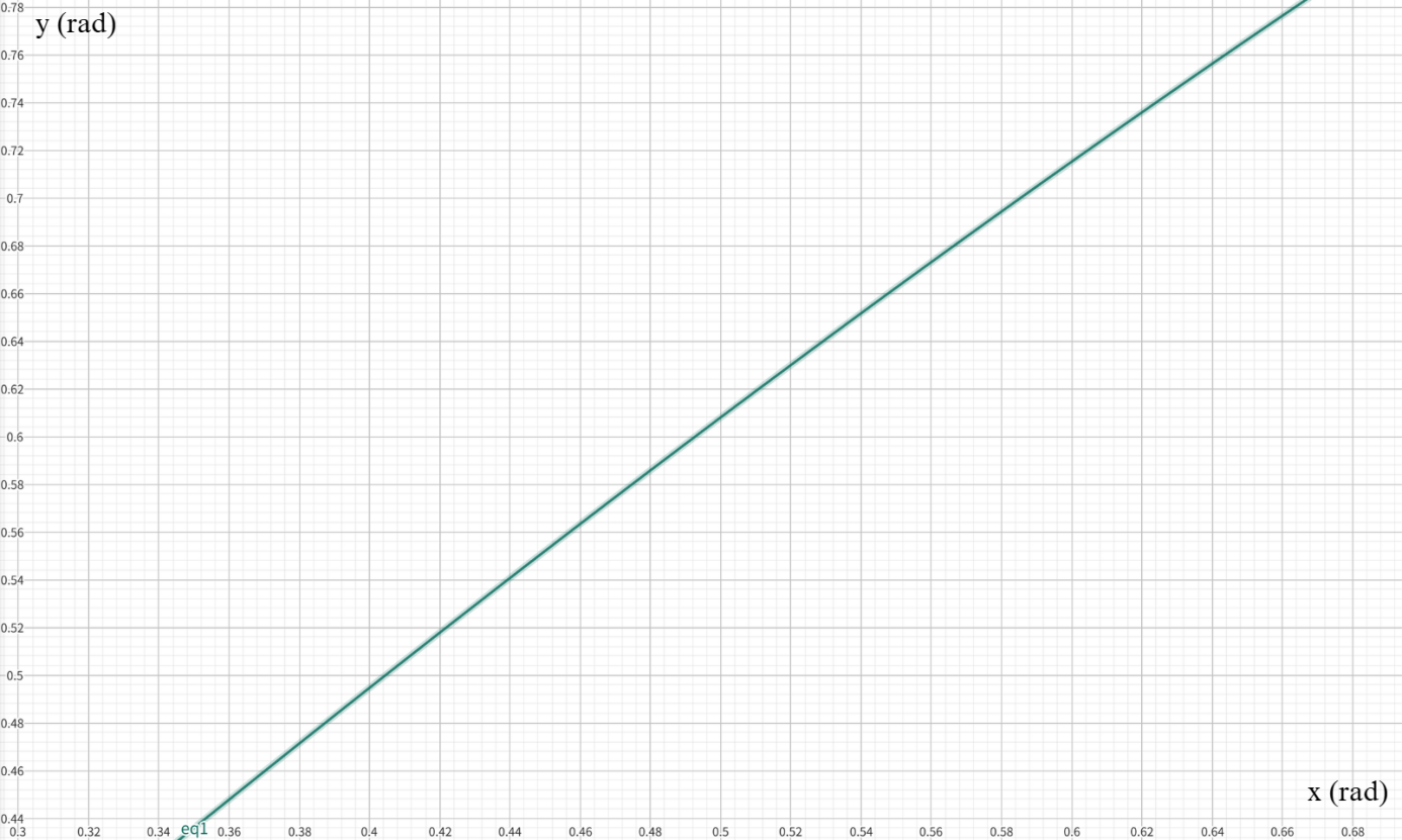
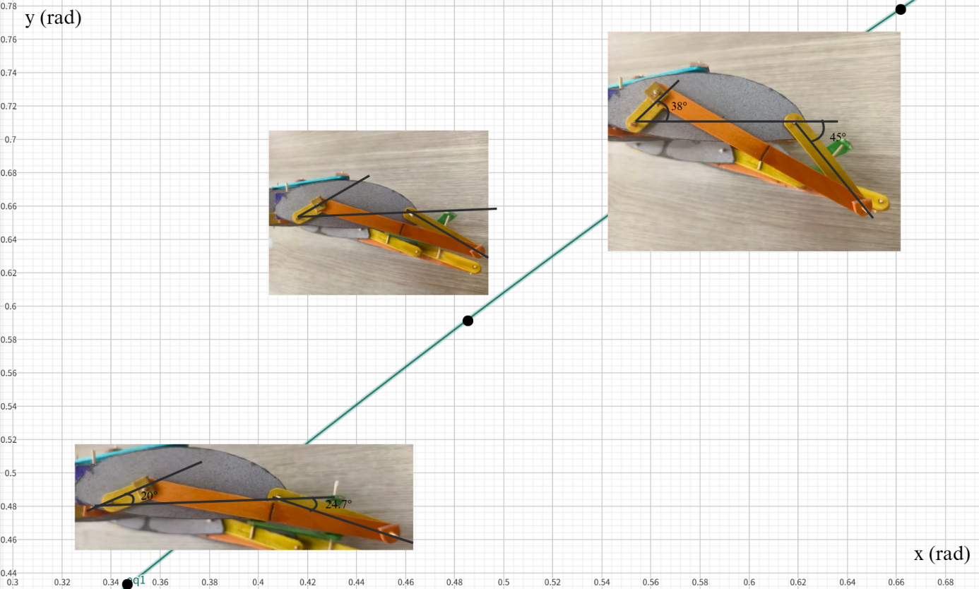
We set the lowest y value to 24.7°, which corresponds to an x value of 20°. As x increases, the y value increases until the x value reaches 38°, where it reaches a maximum of 45°, as shown in Figure 9.
(b) Parallelogram Mechanism
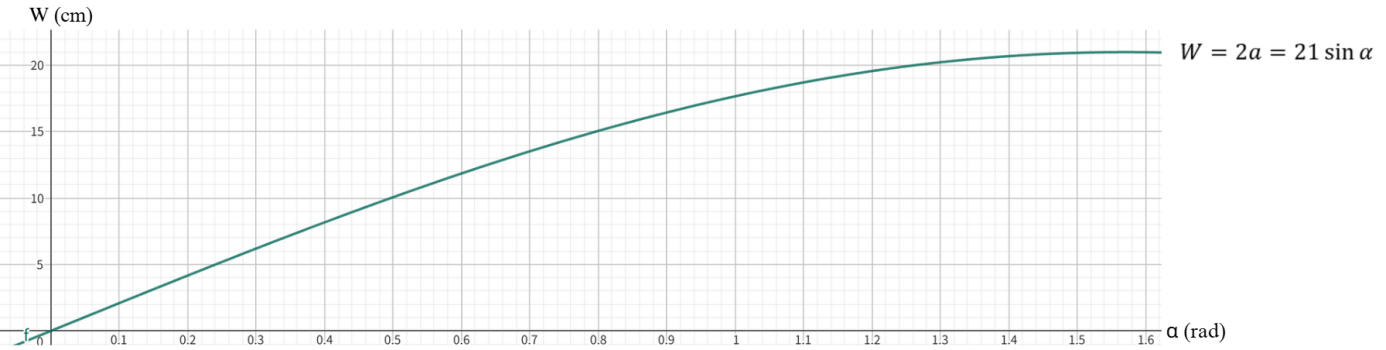
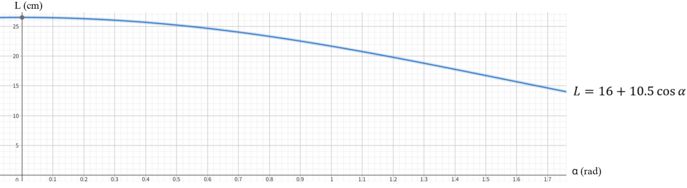
In Figure 10, we want to know how the overall length and width of the glider change as the wing's opening and closing angle α changes when folded.

So we use the sine and cosine trigonometric functions to relate the three variables together.
The diagrams of two implicit functions are shown in Figure 11 and Figure 12.
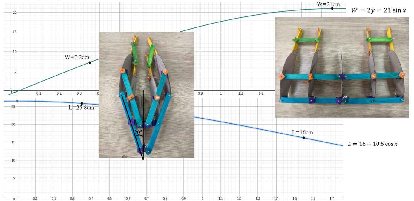
In Figure 13, due to the thickness of the 4-bar linkage in the actual model, we set α to a minimum of 20°. At this point, W can reach 7.2 cm and L can reach 25.8 cm. When the glider is in the deployed state, α can reach 90°, at which point W is 21 cm and L is 16 cm.
3.2. Design 2: parameter analysis
The fuselage of a glider can be viewed as a left-right symmetrical structure, with each side consisting of two upper and lower five-bar linkage mechanism.
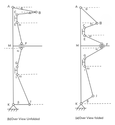
As shown in Figure 14, half of the glider fuselage can be simplified from the front view into a planar linkage mechanism composed of two upper and lower five-bar mechanisms, with a common horizontal sliding lower link in the middle. The degrees of freedom of this connecting rod mechanism can be calculated using the Kutz Bach criterion:
Therefore, this connecting rod mechanism has only one degree of freedom.
We take the distance MF between sliding pair F and point M as the input variable(x) of this link mechanism, and obtain two output angles α and β. Then, considering the displacement in the horizontal and numerical directions, the following set of equations can be listed:
The above system of equations can be used to solve for α(x) and β(x), which are two functions of the variable x:
When the connecting rod length is equal to the connecting rod length in the model, the theorical graphs of these two functions can be drawn, as shown in Figure 15.
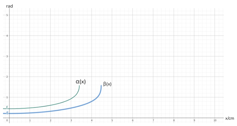
Based on the actual situation of our model, the value range of x is between 1 and 3.4 centimetres, α varies between 0.482 and 1.470, β varies between 0.238 and 0.573.
4. Conclusion
Based on the results and discussions presented above, the following conclusions are obtained:
Future work
(1) For design 1, the value shown for the bar linkage couldn’t play the maximum role (range of angles’ variation) so they must be optimized.
(2) For design 1, possibly use scissor-like elements or look to satellite solar panels for inspiration to replace the parallelogram, reinforcing the stability of the wing.
(3) For design 2, also optimize the value and balance the ratio of the above part and base part (getting access to normal gliders).
Advantages and disadvantages
(1) For design 1, the ability to change direction and speed plays a significant role in facing various conditions in terms of taking off, dropping down, weather conditions, especially wind, and obstruction. But it has high difficulty and trouble operating the bar for changing angles.
(2) For design 2, using two umbrella-like elements makes it convenient and automatic for folding and is also suitable for installing elements in study case 1 while it is complex and difficult to calculate and choose a special length of bars according to the formula in the discussion part. In addition, more connecting bars lead to an increasing weight of the whole structure as well as less space for humans.
Author contribution
Yuxuan Lin, Zhengxi Lin,and Kaizhi Yang contributed equally to this work and should be considered co-first authors.
References
[1]. Zhong, Y. (2025). Motion structures: Deployable assemblies of mechanisms [PowerPoint slides]. University of Oxford, Department of Engineering Science.
[2]. Zhong, Y. (2007). Motion structures extend their reach. Materials Today, 10(12), 53–57.
[3]. Wang, X., & You, Y. (2021). Design and analysis of bionic cobweb Umbrella-Type deployable mechanism. Mechanism and Machine Theory, 167, 104569.
[4]. Zhang, J., Hou, Y., You, C., & Li, C. J. (2023). Design and kinematics characteristics of transient folding mechanism for flapping wing aircraft. Mechanical Science and Technology for Aerospace Engineering. https: //doi.org/10.13433/j.cnki.1003-8728.20230302(in Chinese)
[5]. Kesel, A. B., Philippi, U., & Nachtigall, W. (1998). Biomechanical aspects of the insect wing: an analysis using the finite element method. Computers in Biology and Medicine, 28(4), 423-437.
[6]. Truong, Q.-T., Argyoganendro, B. W., & Park, H. C. (2014). Design and demonstration of insect mimicking foldable artificial wing using four-bar linkage systems. Journal of Bionic Engineering, 11(4), 449-458.
[7]. Zhao, Z. F., Qi, M. S., Feng, J. K., Zhang, W., Wang, J. Y., & Zhang, J. P. (2017). Design and Simulation of Ornithopter based on Four-bar Mechanism. Journal of Mechanical Transmission, 41(11), 87 - 91. (in Chinese)
[8]. Rooney, J., & Duffy, J. (1972). Optimum Synthesis of Four-Bar Mechanism by Using Relative Angle Method: A Comparative Performance Study. In: 12th ASME Mechanisms Conference (pp. 1-12). San Francisco: [s. n.].
[9]. Yang, T. L. (1996). Basic theory of mechanical systems: Structural studies, kinematics, kinetics. Beijing: China Machine Press. (in Chinese)
[10]. Faber, J., Kurahashi, T., & Saito, K. (2023). Earwig-inspired foldable origami wing for micro air vehicle gliding. Frontiers in Robotics and AI, 10, 1255666.
[11]. Subash, T., Touseef, Y., Patel, D. Y., Gowda, H. N. H., & Soniya, K. S. (2024). Literature study on foldable flapping wing mechanisms. International Advanced Research Journal in Science, Engineering and Technology, 11(3), 80–90.
Cite this article
Lin,Y.;Lin,Z.;Yang,K. (2025). Experimental Research on Foldable Gliding Wing with Flap Wing. Applied and Computational Engineering,187,20-30.
Data availability
The datasets used and/or analyzed during the current study will be available from the authors upon reasonable request.
Disclaimer/Publisher's Note
The statements, opinions and data contained in all publications are solely those of the individual author(s) and contributor(s) and not of EWA Publishing and/or the editor(s). EWA Publishing and/or the editor(s) disclaim responsibility for any injury to people or property resulting from any ideas, methods, instructions or products referred to in the content.
About volume
Volume title: Proceedings of CONF-FMCE 2025 Symposium: Semantic Communication for Media Compression and Transmission
© 2024 by the author(s). Licensee EWA Publishing, Oxford, UK. This article is an open access article distributed under the terms and
conditions of the Creative Commons Attribution (CC BY) license. Authors who
publish this series agree to the following terms:
1. Authors retain copyright and grant the series right of first publication with the work simultaneously licensed under a Creative Commons
Attribution License that allows others to share the work with an acknowledgment of the work's authorship and initial publication in this
series.
2. Authors are able to enter into separate, additional contractual arrangements for the non-exclusive distribution of the series's published
version of the work (e.g., post it to an institutional repository or publish it in a book), with an acknowledgment of its initial
publication in this series.
3. Authors are permitted and encouraged to post their work online (e.g., in institutional repositories or on their website) prior to and
during the submission process, as it can lead to productive exchanges, as well as earlier and greater citation of published work (See
Open access policy for details).
References
[1]. Zhong, Y. (2025). Motion structures: Deployable assemblies of mechanisms [PowerPoint slides]. University of Oxford, Department of Engineering Science.
[2]. Zhong, Y. (2007). Motion structures extend their reach. Materials Today, 10(12), 53–57.
[3]. Wang, X., & You, Y. (2021). Design and analysis of bionic cobweb Umbrella-Type deployable mechanism. Mechanism and Machine Theory, 167, 104569.
[4]. Zhang, J., Hou, Y., You, C., & Li, C. J. (2023). Design and kinematics characteristics of transient folding mechanism for flapping wing aircraft. Mechanical Science and Technology for Aerospace Engineering. https: //doi.org/10.13433/j.cnki.1003-8728.20230302(in Chinese)
[5]. Kesel, A. B., Philippi, U., & Nachtigall, W. (1998). Biomechanical aspects of the insect wing: an analysis using the finite element method. Computers in Biology and Medicine, 28(4), 423-437.
[6]. Truong, Q.-T., Argyoganendro, B. W., & Park, H. C. (2014). Design and demonstration of insect mimicking foldable artificial wing using four-bar linkage systems. Journal of Bionic Engineering, 11(4), 449-458.
[7]. Zhao, Z. F., Qi, M. S., Feng, J. K., Zhang, W., Wang, J. Y., & Zhang, J. P. (2017). Design and Simulation of Ornithopter based on Four-bar Mechanism. Journal of Mechanical Transmission, 41(11), 87 - 91. (in Chinese)
[8]. Rooney, J., & Duffy, J. (1972). Optimum Synthesis of Four-Bar Mechanism by Using Relative Angle Method: A Comparative Performance Study. In: 12th ASME Mechanisms Conference (pp. 1-12). San Francisco: [s. n.].
[9]. Yang, T. L. (1996). Basic theory of mechanical systems: Structural studies, kinematics, kinetics. Beijing: China Machine Press. (in Chinese)
[10]. Faber, J., Kurahashi, T., & Saito, K. (2023). Earwig-inspired foldable origami wing for micro air vehicle gliding. Frontiers in Robotics and AI, 10, 1255666.
[11]. Subash, T., Touseef, Y., Patel, D. Y., Gowda, H. N. H., & Soniya, K. S. (2024). Literature study on foldable flapping wing mechanisms. International Advanced Research Journal in Science, Engineering and Technology, 11(3), 80–90.