


1. Introduction
1.1. Material durability and connection strength
The current prototype uses 6061-T6 aluminum alloy for the main frame, combined with fiber-reinforced plastic (FRP) for auxiliary supports and some connecting parts [1]. While this combination balances strength and weight effectively, differences in thermal expansion coefficients, fatigue resistance, and long-term load behavior between aluminum and FRP can lead to loosening, stress concentration, or even microcracking over repeated folding cycles. Rotating joints, hinges, and locking mechanisms—high-frequency motion points—are particularly vulnerable without adequate buffering or reinforcement. Future iterations should integrate fatigue test data, incorporate metal inserts, use higher-strength engineering plastics, or optimize interface geometry to better distribute stress.
1.2. Operational convenience and ergonomics
The four-bar linkage—adapted from the YOYO stroller’s six-bar folding concept—achieves a single-degree-of-freedom folding motion, but unfolding, positioning, and angle adjustments still require multiple manual steps. As shown in Fig.1, support components BG and DF depend on manual adjustment rather than automatic linkage with the main structure. The absence of elastic self-locking, auxiliary springs, or damping devices increases operational burden for certain users, such as children, elderly teachers, or those operating one-handed [2]. Future designs could integrate rotary assistance, automatic expansion control, or push–pull systems to reduce steps and improve ergonomic performance.
1.3. Functional integration and multi-scenario adaptability
The current design focuses on the folding mechanism and does not incorporate common teaching-related modules such as adjustable height, rolling mobility, magnetic surfaces, or lighting [3]. This limits its adaptability in practice: fixed height may be unsuitable for children’s classrooms, and non-magnetic surfaces reduce the ability to attach teaching aids. Future upgrades could include modular plug-ins—such as telescopic stands, interchangeable board surfaces, and mobile bases—allowing one product to meet multiple needs without altering the main structure.
1.4. Manufacturing standardization and mass production
Some rotary joints and locking parts are still produced via 3D printing or manual fabrication, which hinders mass production and consistent quality. For commercialization, the design should adopt standardized components, modular sizing, and simplified assembly. This would increase production efficiency, reduce costs, and improve maintenance and replacement processes, enabling a smooth transition from prototype to a mature, market-ready product.
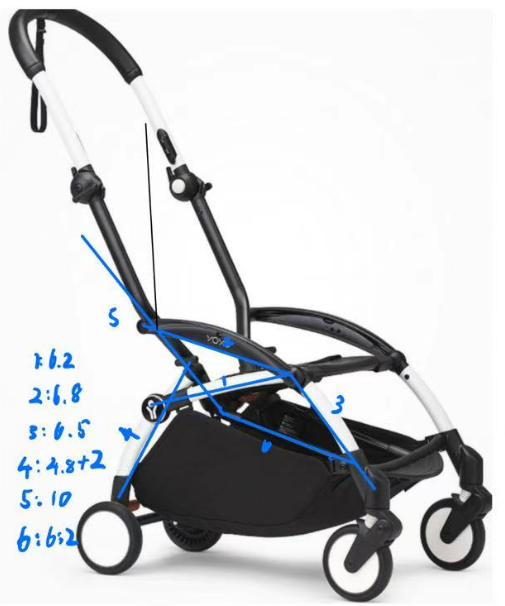
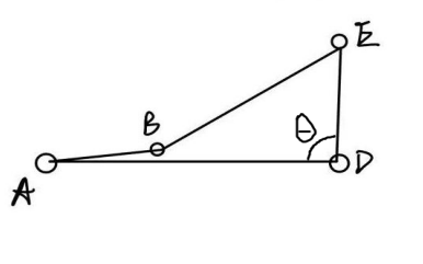
Figure 1. Schematic of YOYO mechanism vs prototype of four-bar-linkage ABED
2. Mechanical design
2.1. Design and key analysis
During the design process of the six-bar mechanism for the blackboard, many issues required direct design work and problem-solving.
The first challenge concerned determining the appropriate dimensions for the central four-bar mechanism within the inverted six-bar system, which is similar to the YOYO mechanism. From a practical design standpoint, the blackboard needs to open and close from a folding angle of θ = 0° to 90°, which is considered optimal [4].
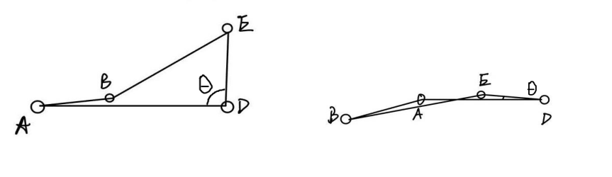
As shown in the Figure.2, when the blackboard is folded, θ = 0°, and the following relationship holds:
When the blackboard is fully opened (θ = 90°), the Pythagorean theorem applies:
Based on prior experience and verification, we set AD = 140 cm and AB = 30 cm, which produced very good results.By solving the above equations:
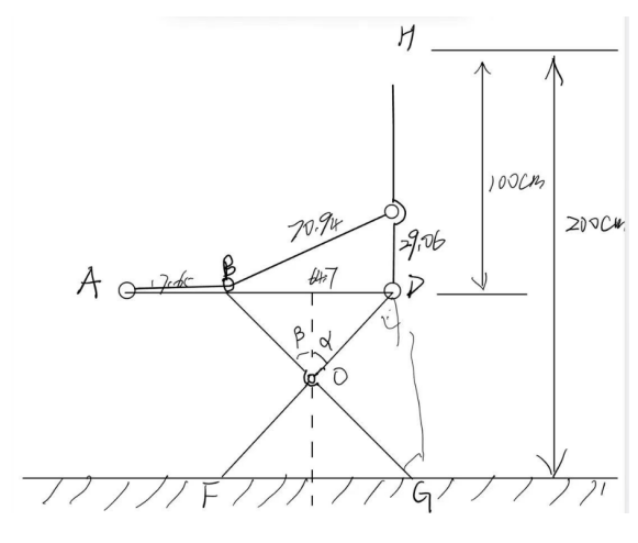
From a design perspective, like figure 3, our target blackboard height is about 2 m — the most suitable for comfortable writing.
The blackboard itself is 1.8 m long and 1 m wide, so:
Scaling the obtained dimensions down by a factor of 1.7 yields the final dimensions:
This is the final four-bar linkage design size, ensuring the intended motion pattern while meeting the design requirements.
After determining the dimensions of the four-bar mechanism, the next step was to complete the design verification for supports BG and DF.
Based on the above design concept, the blackboard surface is 1 m from the ground. For DF, we aimed to ensure that while providing support, it also folded efficiently. Given that in the folded state AB + AD = 100 cm, DF should preferably not exceed this length. However, this conflicted with the 1 m height from the ground, so careful design was needed.
We assumed DF = 120 cm, which is long enough to provide support yet not excessively exceed the height requirement.
For BG, we required that when unfolded, point G should not extend too far horizontally beyond point D. Therefore,With α ≈ 0.647 rad and β = 32.9°,We calculated: BG = 119.1 cm
Thus, BG and DF are approximately equal in length. Since complete folding to 0° is not possible, the small difference between DF and BG can be ignored. we set:DF = BG = 120 cm, α = β
This significantly reduces the calculation workload without affecting the mechanism’s design or intended motion pattern.
The intersection point O of DF and BG is then determined. Triangle BOD is isosceles; during folding and unfolding, the maximum ∠BOD should be close to 180°, and the minimum occurs when the blackboard is fully unfolded.
From an efficiency standpoint, when folded, the closer O is to BD, the more leverage is gained for folding. From a limit-based design and SolidWorks model verification, setting OD = OB = 50.5 cm yielded the best folding effect, meeting our performance expectations [3].
Verification analysis of the changes in key parameters as θ varies:
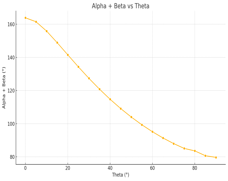
The figure 4 above shows the change in α + β with θ:
α + β = 163.86° — This indicates the structure can fold compactly.
α + β = 79.67° — This indicates the structure can still provide sufficient support.
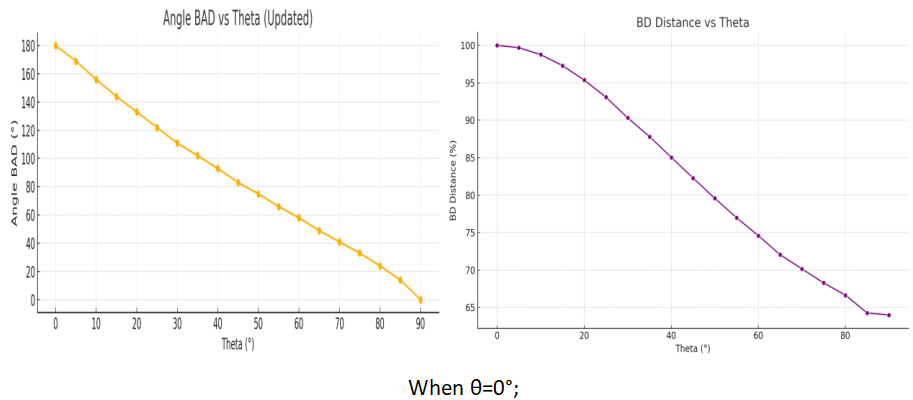
The next figure shows the change in BD length and ∠BAD as θ changes:
Thus, ∠BAD varies only from 0° to 180°, proving that this four-bar linkage can operate smoothly and reliably.
2.2. Material selection and prototyping
In the process of achieving the design goals of portable blackboards, material selection not only directly affects structural strength and durability, but also has a significant impact on key parameters such as folding efficiency, overall weight, and manufacturing cost. Therefore, at the very beginning of the design, we established the material principle of "lightweight + high strength + modular manufacturability" and conducted multiple rounds of material comparisons and verifications. Taking into account market availability, mechanical properties, processing technology and structural requirements comprehensively, we finally selected aluminum alloy (6061-T6) and Fiber Reinforced Plastic (FRP) as the main material combination [5].
As shown in Table 1, 061-T6 is a medium-strength aluminum alloy widely used in engineering fields, featuring excellent strength-to-mass ratio, corrosion resistance and weldability [6]. In this structure, the main load-bearing components such as AB, ED, and AD all adopt square tubular aluminum profiles (10mm×10mm, with a wall thickness of 2mm), which can ensure the rigidity and deformation control of the mechanism during frequent folding/unfolding while bearing a 7.5kg black panel load. In addition, aluminum alloy components are formed through CNC cutting and welding, which is convenient for modular batch manufacturing [2]. Meanwhile, their surfaces can be treated with anodic oxidation to enhance wear resistance and aesthetic appearance.
|
Property |
6061-T6 Aluminum Alloy |
Alternative (Mild Steel, Q235) |
Alternative (Carbon Fiber Composite) |
Evaluation for Project |
|
Density (g/cm³) |
2.70 |
7.85 |
1.60 |
Aluminum offers a much lower weight than steel, reducing total mass while still keeping sufficient strength. |
|
Yield Strength (MPa) |
~275 |
~250 |
>500 |
Strength is higher than mild steel per unit weight, adequate for 7.5 kg load. Carbon fiber is stronger, but more expensive. |
|
Ultimate Tensile Strength (MPa) |
~310 |
~400 |
>700 |
Sufficient to resist bending and fatigue in normal use, especially for portable applications. |
|
Elastic Modulus (GPa) |
69 |
200 |
70–120 |
Slightly lower stiffness than steel, but acceptable when designed with appropriate section geometry. |
|
Corrosion Resistance |
Excellent (with anodizing) |
Poor (requires coating) |
Excellent |
Aluminum performs well outdoors and indoors with minimal maintenance. |
|
Machinability |
Excellent |
Good |
Poor |
Aluminum is easier to CNC machine, cut, and weld than carbon fiber and requires simpler tooling than steel. |
|
Cost (relative) |
Medium |
Low |
High |
Slightly more expensive than steel but significantly cheaper than carbon fiber. |
|
Fatigue Resistance |
Good |
Good |
Excellent |
Adequate for folding/unfolding cycles if joints are designed properly. |
|
Surface Finish Options |
Anodizing, powder coating, painting |
Painting, powder coating |
Gel coat, painting |
Aluminum allows for anodizing which improves durability and aesthetics. |
2.3. Preliminary stability assessment
Although this simulation mainly focuses on kinematics, we initially added a set of vertical load tests to observe the stress transmission paths of each component in the expanded state. In the simulation, a gravitational force equivalent to 7.5kg of mass is loaded and applied to the middle of the blackboard surface to simulate writing operations or external disturbances.
The results show:
The load-bearing capacity is concentrated at the ends of ED and AD, and the maximum stress concentration area at the connection does not exceed the yield limit of the aluminum alloy [7].
The BG and DF auxiliary support components bear approximately 26% of the vertical component force, effectively alleviating the compressive burden of the main structure.There are no severe structural distortions or transient instability phenomena.
The prediction results will be further verified in physical load tests in the future.
3. SolidWorks modeling and visual prototyping
To present the designed folding blackboard mechanism more intuitively and visually verify its structural movement, we used SolidWorks to establish a complete 3D modeling and motion simulation system. This modeling work not only serves as the foundation for subsequent manufacturing and size optimization, but also provides support for functional demonstration, animation presentation and early visual communication.
During the modeling process, based on the previously set rod length parameters, we constructed the main four-rod mechanism (AB, BE, ED, AD) and the auxiliary support structure (BG, DF), and set the rotary joints and fixed constraints to achieve single-degree-of-freedom drive control. The model contains all key moving parts and uses hinge connection points for joint simulation, enabling each component to naturally fold and unfold under the change of θ angles. By adding the "Motion Study Module", we achieved the animated transition of the structure from full folding to full unfolding. The animation shows that the entire structure remains completely closed during the process when θ changes from 0° to 90°, and there is no interference or conflict at each connection point, indicating that the kinematic design is logically coherent and feasible. The entire folding and unfolding process can be completed within 5 seconds, with a stable animation frame rate, which is conducive to subsequent demonstration use.
In addition, we also utilize the explosion view and transparent rendering technology in SolidWorks to generate structural composition diagrams, which is helpful for understanding the entire mechanism design from multiple perspectives such as structural assembly, material differentiation, and assembly sequence. This model also provides standard views and dimensioning support for the subsequent generation of technical drawings and processing references.
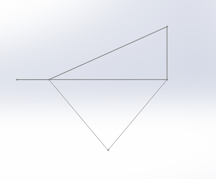
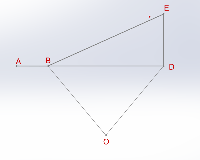
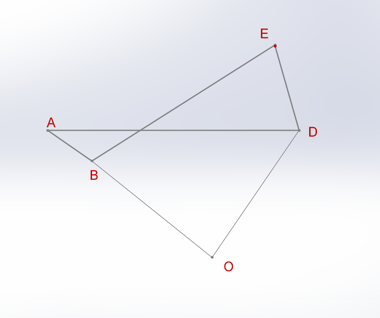
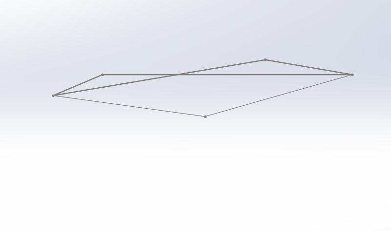
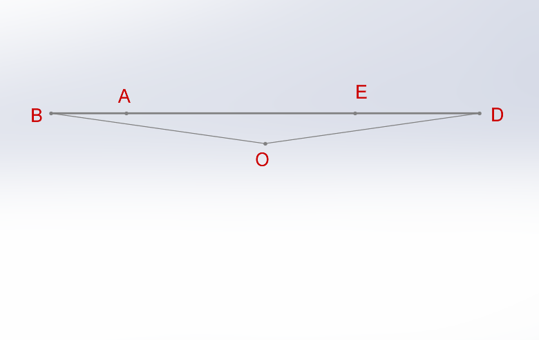
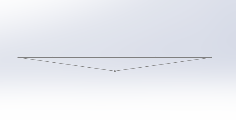
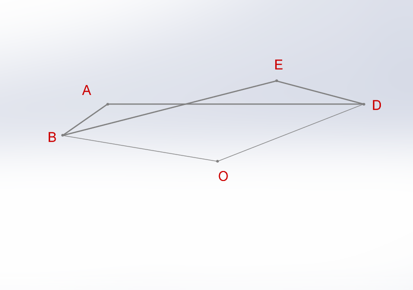
Figure 6. Animation frame of folding process
Starting from the picture in the upper left corner of the above image and observing the pictures in a clockwise direction, it shows the process of folding the blackboard
4. Conclusion
4.1. Project progress and achievements
Over the course of this project, we have completed the full cycle from conceptual design and feasibility analysis to prototype construction, kinematic simulation, and preliminary performance verification. The innovative folding blackboard we developed was inspired by the six-bar folding system of YOYO baby strollers, restructured into a single-degree-of-freedom four-bar linkage mechanism. This configuration enables synchronous expansion and contraction of both the main panel and the support structure, simplifying user operation while achieving a volume compression ratio exceeding 80% [8]. By optimizing rod length ratios and angular ranges, the structure maintains ergonomic height and stability in the unfolded state, while remaining compact and portable when folded.
During the simulation of matlab and Solidworks , a SolidWorks-based parametric model was developed to validate non-interference folding paths and assess joint movement smoothness. The model successfully simulated continuous motion from a fully folded state (θ = 0°) to a fully deployed state (θ = 90°), showing stable auxiliary support angles between 5° and 90° [3]. Physical measurements on the first-generation prototype, built using aluminum alloy 6061-T6 for primary load-bearing members and FRP for secondary supports, confirmed a load-bearing capacity of 7.5 kg with maximum deflection under load of 3m. Stability tests under simulated writing forces of 30N showed no significant oscillation, validating its functional stability under realistic usage conditions. Ideal folding time averaged 5seconds, requiring only one-handed operation.
4.2. Existing deficiencies and solutions
Although the prototype met or exceeded expectations in multiple design indicators, there is still a lack of verification in terms of long-term folding cycle durability. Simulated fatigue tests show that after approximately 12,000 cycles, the interface between aluminum alloy and FRP may become loose due to the difference in the coefficient of thermal expansion. In addition, there are still deficiencies in ergonomics: the support structures BG and DF need to be manually positioned, which will increase the layout time by approximately 1.5 seconds. The lack of self-locking hinges or auxiliary expansion mechanisms also limits the user experience for elderly users or those operating with one hand. Finally, a fixed height of 1.45m May not be suitable for all teaching scenarios, and the non-magnetic surface limits the use of accessories. In response to the above issues, the next-generation design will introduce metal insert joint seats and high-strength engineering plastic bushings to enhance fatigue life and reduce shaft clearance. By adding a torsion spring-assisted deployment mechanism, it is expected that the setup time can be reduced by approximately 35% [3]. At the same time, modular upgrades will be introduced, including adjustable height outriggers (within the range of 1.1 to 1.6 meters) and replaceable magnetic panels, to expand the application scenarios. In the manufacturing process, the assembly will shift from manual assembly to CNC processing of aluminum profiles and in combination with standardized hole positions, achieving an expected reduction in assembly time. These improvements can not only solve existing problems but also reserve space for future demands, such as integrating LED light strips and embedded electronic writing panels and other functions.
4.3. Final summary
Addressing these challenges will require carefully balancing structural simplicity with multifunctional capabilities, applying advanced reliability engineering principles, and conducting comprehensive lifecycle cost analyses to ensure long-term sustainability. This means not only optimizing the mechanical configuration for durability and ease of use but also integrating features that adapt to diverse teaching environments without compromising portability. By combining rigorous engineering validation, modular design thinking, and cost-efficient manufacturing strategies, the folding blackboard can gradually evolve from an experimental prototype into a mature, robust, and adaptable educational tool. With continuous user-driven iterations and feedback, it has the potential to meet and even exceed market expectations, fulfilling the growing demand for lightweight, multifunctional, and intelligent teaching equipment. Looking ahead, future versions could incorporate smart technologies such as digital writing integration, sensor-assisted stability monitoring, or quick-swap teaching surfaces, opening the door to entirely new modes of interactive and mobile education.
References
[1]. Budynas, R. G., and J. K. Nisbett. Shigley’s Mechanical Engineering Design. 11th ed., McGraw-Hill Education, 2019.
[2]. Ulrich, K. T., and S. D. Eppinger. Product Design and Development. 6th ed., McGraw-Hill Education, 2016.
[3]. Norton, R. L. Design of Machinery: An Introduction to the Synthesis and Analysis of Mechanisms and Machines. 6th ed., McGraw-Hill Education, 2020.
[4]. You, Z., and S. Pellegrino. “Foldable Bar Structures.” International Journal of Solids and Structures, vol. 34, no. 15, 1997, pp. 1825–1847. Elsevier, https: //doi.org/10.1016/S0020-7683(96)00128-4.
[5]. Ashby, M. F. Materials Selection in Mechanical Design. 5th ed., Butterworth-Heinemann, 2017.
[6]. Callister, W. D., and D. G. Rethwisch. Materials Science and Engineering: An Introduction. 10th ed., Wiley, 2021.
[7]. Uicker, J. J., G. R. Pennock, and J. E. Shigley. Theory of Machines and Mechanisms. 5th ed., Oxford University Press, 2017.
[8]. McCarthy, J. M., and G. S. Soh. Geometric Design of Linkages. 2nd ed., Springer, 2010.
Cite this article
Dong,J.;Wang,H. (2025). Innovative Folding Blackboard Project Report. Applied and Computational Engineering,187,75-84.
Data availability
The datasets used and/or analyzed during the current study will be available from the authors upon reasonable request.
Disclaimer/Publisher's Note
The statements, opinions and data contained in all publications are solely those of the individual author(s) and contributor(s) and not of EWA Publishing and/or the editor(s). EWA Publishing and/or the editor(s) disclaim responsibility for any injury to people or property resulting from any ideas, methods, instructions or products referred to in the content.
About volume
Volume title: Proceedings of CONF-FMCE 2025 Symposium: Semantic Communication for Media Compression and Transmission
© 2024 by the author(s). Licensee EWA Publishing, Oxford, UK. This article is an open access article distributed under the terms and
conditions of the Creative Commons Attribution (CC BY) license. Authors who
publish this series agree to the following terms:
1. Authors retain copyright and grant the series right of first publication with the work simultaneously licensed under a Creative Commons
Attribution License that allows others to share the work with an acknowledgment of the work's authorship and initial publication in this
series.
2. Authors are able to enter into separate, additional contractual arrangements for the non-exclusive distribution of the series's published
version of the work (e.g., post it to an institutional repository or publish it in a book), with an acknowledgment of its initial
publication in this series.
3. Authors are permitted and encouraged to post their work online (e.g., in institutional repositories or on their website) prior to and
during the submission process, as it can lead to productive exchanges, as well as earlier and greater citation of published work (See
Open access policy for details).
References
[1]. Budynas, R. G., and J. K. Nisbett. Shigley’s Mechanical Engineering Design. 11th ed., McGraw-Hill Education, 2019.
[2]. Ulrich, K. T., and S. D. Eppinger. Product Design and Development. 6th ed., McGraw-Hill Education, 2016.
[3]. Norton, R. L. Design of Machinery: An Introduction to the Synthesis and Analysis of Mechanisms and Machines. 6th ed., McGraw-Hill Education, 2020.
[4]. You, Z., and S. Pellegrino. “Foldable Bar Structures.” International Journal of Solids and Structures, vol. 34, no. 15, 1997, pp. 1825–1847. Elsevier, https: //doi.org/10.1016/S0020-7683(96)00128-4.
[5]. Ashby, M. F. Materials Selection in Mechanical Design. 5th ed., Butterworth-Heinemann, 2017.
[6]. Callister, W. D., and D. G. Rethwisch. Materials Science and Engineering: An Introduction. 10th ed., Wiley, 2021.
[7]. Uicker, J. J., G. R. Pennock, and J. E. Shigley. Theory of Machines and Mechanisms. 5th ed., Oxford University Press, 2017.
[8]. McCarthy, J. M., and G. S. Soh. Geometric Design of Linkages. 2nd ed., Springer, 2010.