


1. Introduction
With the intensification of the global energy crisis, the search for green and sustainable renewable energy has become an urgent task. At present, the methods of ocean green energy development usually include wind energy, wave energy, tidal energy, and ocean thermal energy. Among them, ocean wind energy is a kind of open renewable energy, and its development technology is advanced and relatively mature. There is great space for future development, and floating offshore wind turbines are becoming more and more mature [1].
However, marine green energy utilization also faces many technical difficulties and environmental problems. Compared with onshore wind power system, offshore wind power generator is in a more complex system, and the components are exposed for a long time, facing the problem of corrosion protection. Furthermore, the load generated by waves also puts forward higher requirements for the structure stability [2]. These issues imply a further increase in the initial construction investment and later labor maintenance costs. Therefore, the development of offshore wind power platforms with more stable structures and high energy efficiency is imminent. China's seabed structure is complex and diverse and deep-sea wind energy resources are more abundant than offshore, so floating offshore wind power towers with low requirements for seabed environment are attracting attention. At present, the mainstream floating wind tower platform uses a single column, tension leg and three floating body and other basic structures [3]. While the sea surface environment is complex, it is needed to choose a simpler and more stable, construction-friendly structure design. Figure 1 shows the new offshore wind power platform structure.
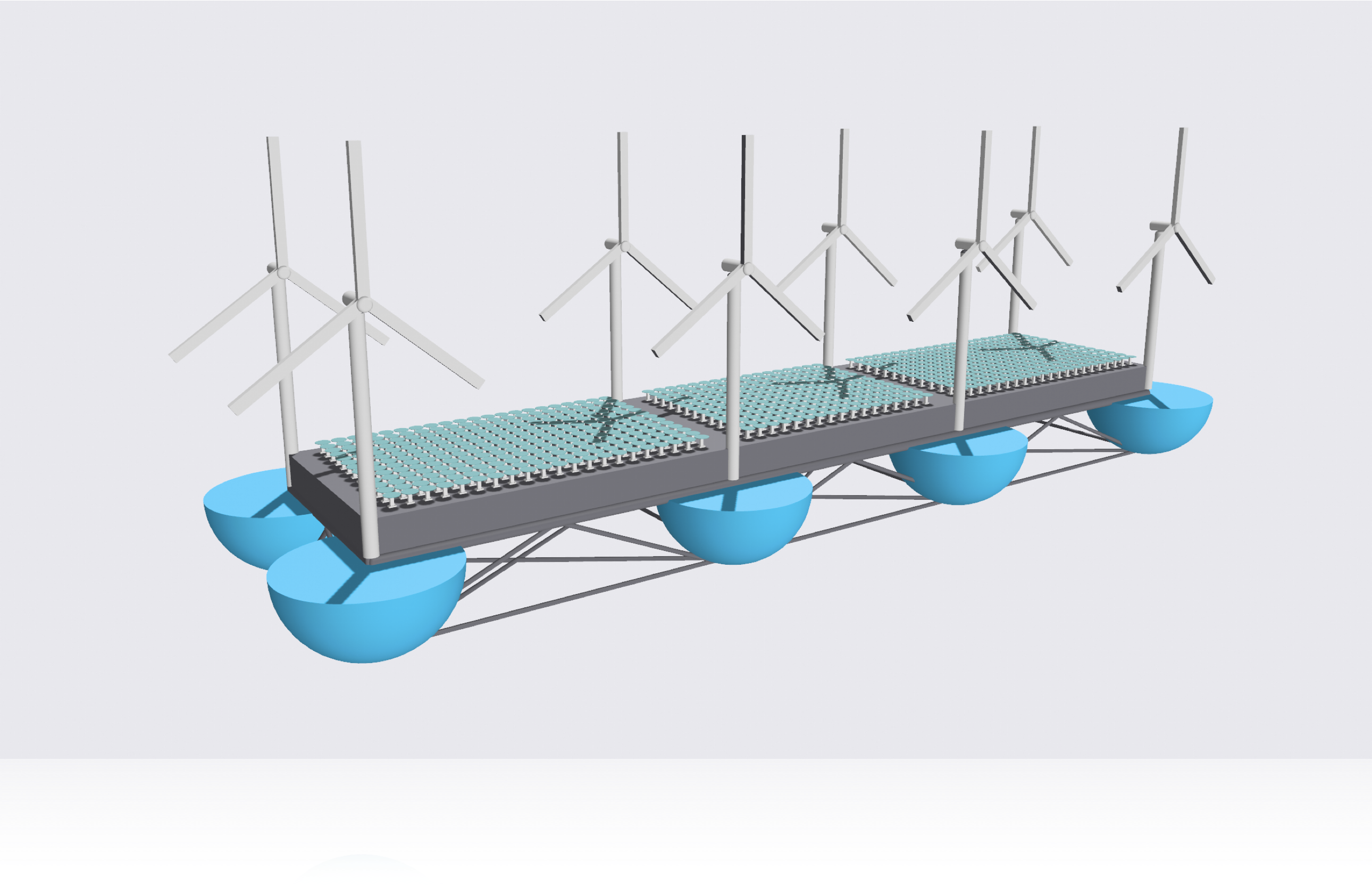
Figure 1. Floating offshore wind PV platform.
The foundation structure of this platform adopts a new hemispherical shell foundation structure form [3], and each foundation structure is linked by trusses. On top of the platform, smart flower solar panels are laid on its water outlet area, aiming to increase the full collection of solar energy, improve the overall energy conversion rate of the platform, and maximize its economic benefits [4].
There are currently several problems with the assembly and transportation of floating platforms at sea. There are some difficulties in transporting them from the plant to the port, but this problem can be solved by assembling the parts in sections, and the new floating platforms can be assembled in sections, thus making them easy to transport.
The aim of the research is to increase the efficiency of offshore energy use and improve the stability and viability of the platform.
2. Method
1.1 Design of the floating system structure
Nowadays, offshore wind power development is form near sea to the far sea. In this case, the floating structure is more economical than fixed structure at waters greater than 50 meters deep [5]. So, for the research of the construction here, a floating platform on the sea which combines the offshore wind power and photovoltaic power is needed. Based on the above requirement and some innovative ideas, the construction is worked out. The size of draught fan and photovoltaic power generation structure is referring to the existing technology. The wind power generation equipment uses the JinFeng 87/1500Kw wind driven generator and the photovoltaic power generation equipment uses the innovative Smart flower power generation assembly. As for the size of the main platform is based on the quantity and size of the power generation assemblies. The research of the hemispherical shell type floating foundation is on account of the principle of tumbler.
1.2 Research on the stability
When the ship is at equilibrium, if there is an external force acting on the ship, the ship will out of balance and slope. But if the ship is rebalanced when the external force revokes, this ability is the ship stability [6]. The research about stability here is mainly initial stability, and the initial metacentric height is the distance between the center of gravity and buoyant center, it is an important standard to measure the stability [7]. The center of gravity is calculated by the weight and height of center of gravity of the various parts of the platform, and the buoyant is calculated by the volume of displacement and height of buoyant center of the various parts of the platform. Then the research about ballast is conducted to make the center of gravity under the buoyant center. In the end, the initial metacentric height is calculated by the following formulas.
\( BB1=2×g1o×v1×∆ \) (1)
\( BM=BB1/sinθ \) (2)
BB1 is the distance between buoyant center before slant and buoyant center after slant; g1o is the distance between center of gravity of water inlet wedge and center of front projection of the platform; v1 is the volume of water inlet wedge; ▽ is the volume of displacement; BM is initial metacentric height and the θ is the angle of inclination.
1.3 Research on the stability
1.1.1. Wind load calculation. The wind load calculation formula offered by ABS standard is used here.
\( F=f×V_{k}^{2}×{C_{h}}×{C_{s}}×A \) (3)
The f is a constant and its value is 0.611. the Vk is the design wind speed, Ch and Cs can be gotten by looking up the table. So, the wind load can be calculated by the above formula.
1.1.2. The load calculation. About the wave load calculation, the Morrison force is calculated by the linear wave theory and constant stretching method.
\( Δ=k/D \) (4)
\( {u_{max}}=π×H/T \) (5)
\( Re={u_{max}}×D/ν \) (6)
\( KC=π×H/D \) (7)
The Δ is the drag-coefficient on roughness, the k is the wave number, the D is the base width, the umax is the maximum fluid particle velocity, the Re is the Reynolds number the KC is the Keulegan-Carpenter number (KC).
The water depth is d=100m, the wave height is Hmax=9 m, the corresponding period is Tmax=12 s.
The CD, CM, CA can be calculated by the basic parameters of the sea area, (CD is drag coefficient, CM is inertia coefficient, CA= CM-1). Then the speed and acceleration of water particle can be computed by newton method.
Use Newton Method and Wheeler’s Stretching to calculate the Morrison force for a single base. The first step is to calculate the wave number (k) and the next step is to calculate the velocity and acceleration of individual water quality points, according to the following formulas.
\( u=\frac{πHmax}{Tmax}∙\frac{cosh(ks\frac{d}{d+η})}{sinh(kd)}∙cosα \) (8)
\( a=\frac{∂u}{∂t}\frac{2{π^{2}}Hmax}{{Tmax^{2}}}∙\frac{cosh(ks\frac{d}{d+η})}{sinh(kd)}∙sinα \) (9)
\( η=\frac{{H_{max}}}{2}cosα \) (10)
Where, u is the velocity of individual water quality points; a is the acceleration of individual water quality points; η is the Water surface wave equation; α is the phase angle; d is the water depth
The wave loads are calculated using linear wave theory, but because the foundations are of large dimensions, an integral calculation should be performed AD and AI.
\( d{A_{1}}=ρ\frac{π{dD^{2}}}{4} \) (11)
\( d{A_{D}}=\frac{ρdD}{2} \) (12)
\( dD=s-75 \) (13)
ρ is the seawater density, the dD is the Micro elements of spherical base width.
The wave load calculation can be worked out by the formula of the Morrison force.
\( f={f_{I}}+{f_{D}}+{C_{M}}×{A_{I}}+{C_{D}}×{A_{D}}×u×|u| \) (14)
\( F=\int _{75}^{100+4.5cosα}fds \) (15)
The f is the Morison Force, the fI is the Inertia force formulation, the fD is the Drag force formulation. The Morison force applied to a single foundation is F for a total of 8 foundations and, as the design is of large dimensions, should empirically be doubled.
1.4 Economic valuation
The research about economic is conducted by showing the estimated costs. The costs is calculated by the number of each device, amount of material and their unit prices, then, the manpower construction cost is added to get the final cost.
\( {P_{tot}}={P_{w}}+{P_{S}}+{P_{t}}+{P_{h}}+{P_{p}}+{P_{t2}}+{P_{c}}+{P_{m}} \) (16)
Ptot is the total price. Pw is the price of wind turbines. Ps is the price of Smart Flower Photovoltaic panels. Pt is the price of Tesla charging stations. Ph is the price of hemisphere basics. Pp is the price of platform. Pt2 is the price of trusses. Pc is the price of C30 concrete. Pm is the price of manpower building costs.
3. Results
1.5 The floating system structure
In the developed structure, eight Goldwind 87/1500 kw wind turbines are used, each weighing 128,865 kg, with a total wind power of 12 MW. Wind turbine tower height 67.8 m, blade length 38.5 m, impeller diameter 3.73 m, tower base 4.2 m
The Smartflower has a single installed power of 3.2 KW and weighs 750 KG. 767 units with a total power of 2.45 MW are used in this design. The Smartflower uses the most advanced integrated dual axis sun tracking technology, in this case, it can capture 40% more sun energy than existing equipment [8]. In practical use, the equipment has become the energy supply equipment for NATO special forces. The photovoltaic panels have an open vertical height of 4.81 m, a horizontally placed diameter of 4.74 m, a horizontally placed height of 2.99 m, a column bottom diameter of 1.135 m and a retracted vertical height of 2.85 m.
The platform uses eight hemispherical foundations made of DH32 steel, 20 mm thick, with a radius of 25 m and an individual mass of 407.75 kg.
The truss structure consists of several triangular structures with two layers of x-frames located throughout the lower part of the platform to enhance its stability. The height of the platform is 10 meters, and the thickness is 50 mm. The platform is fitted with smartflower devices on the upper part and supported by x-trusses on the lower part.
1.6 Stability
The results of the volume of displacement can be seen in Table 1.
Table 1. Volume of displacement.
Design draft/m | Volume of displacement/m | Sea-water density/kg/m3 | Water discharge/kg |
30 | 606758.8 | 1025 | 621927770 |
The results of the calculation of the center of buoyancy can be seen in Table 2.
Table 2. Center of buoyancy calculation.
Height of center of buoyancy1/m | Volume of displacement 1/m3 | Height of center of buoyancy 2/m | Volume of displacement 2/m3 | The center of buoyancy/m |
17.125 | 523598.8 | 29.5 | 83160 | 18.82 |
The results of the calculation of the center of gravity without ballast can be seen in Table 3.
Table 3. Center of gravity calculation.
Part | Mass (t) | Part | Center of gravity height |
No ballast platform mass1 /kg | 2446.52 | No ballast center of gravity height1 /m | 17.125 |
No ballast platform mass2 /kg | 21636.27 | No ballast center of gravity height2 /m | 34 |
Fan mass/kg | 1030920 | Height of center of gravity of fan/m | 72.75 |
Photovoltaic equipment mass/kg | 575250 | Height of center of gravity of photovoltaic equipment/m | 41 |
Truss mass1 /kg | 13066.98 | Height of center of gravity of truss1 /m | 0.75 |
Truss mass2 /kg | 23956.13 | Height of center of gravity of truss2 /m | 28.25 |
Truss mass3 /kg | 14230.33 | Height of center of gravity of truss3 /m | 14.5 |
The center of gravity without ballast/m | 59.6 |
Because 59.6 m is higher than18.82 m, the center gravity without ballast is higher than the center of buoyancy. So, the ballast design is conducted, the C30 concrete is used here.
The results of ballast calculation and ballast center of gravity can be seen in the table 4.
Table 4. Ballast and center of gravity calculation.
Density/kg/3 | Volume/m3 | Mass/kg | Height of center of gravity/m | The ballast center of gravity/m |
2500 | 14137.17 | 35342917.35 | 9.375 | 11.66 |
Foe 11.66 m is lower than 18.82 m, the ballast center of gravity is lower than center of buoyancy.
Based on computation: the distance between centre of gravity of water inlet wedge and centre of front projection of the platform is 113.9 m, and the volume of water inlet wedge is 525233.93 m3. Since the initial metacentric height is 16.12 bigger than zero, the structure has a splendid stability.
1.7 Load calculation
1.1.3. Wind load calculation. The result of wind load calculation cam be seen in the table 5.
Table 5. Wind load calculation.
Ch | Cs | A | F | |
Platform | 1.00 | 1.0 | 2310 | 170780.61 |
Photovoltaic equipment main body | 1.00 | 0.5 | 3068 | 113410.15 |
Photovoltaic panel | 1.00 | 0.4 | 4901.9 | 144960.95 |
Tower barrel | 1.2 | 0.5 | 2160 | 95814.58 |
Flabellum | 1.37 | 1.0 | 3696 | 374351.10 |
When the wind speed is 11m/s, the total wind load pressure on the structure is 899317.385 N. Unit wind load is 55.73 N and Wind load on the monolithic photovoltaic equipment is 258371.102 N. Wind load on integral wind system is 470165.673 N.
1.1.4. Wave load calculation. The values of CA, CD, CM are firstly calculated. k is 5*10-5 m; Δ is 10-6, umax is 1.178 m/s; Re is 4.281×10⁷; KC is 0.5655 which is smaller than 0.65. CA, CD and CM are 1.0, 0.65 and 2.0, respectively.
The Morrison force image of a single foundation is shown in Figure 2
F= \( sinα∙250.735(9cosα+200)[8.17365{cos^{2}}α+72.6116cosα+3.78088cos2α+(-41.441cosα-0.455211cos2α-460.921)∙sinh{(\frac{46.5}{cosα+22.22})}+2022.01]-29.81{cos^{2}}α[202.449{cos^{2}}α+4820.88cosα+(0.325182{cos^{2}}α+14.4525cosα+160.584)cosh(\frac{46.5}{cosα+22.22})+8562.35]N \)
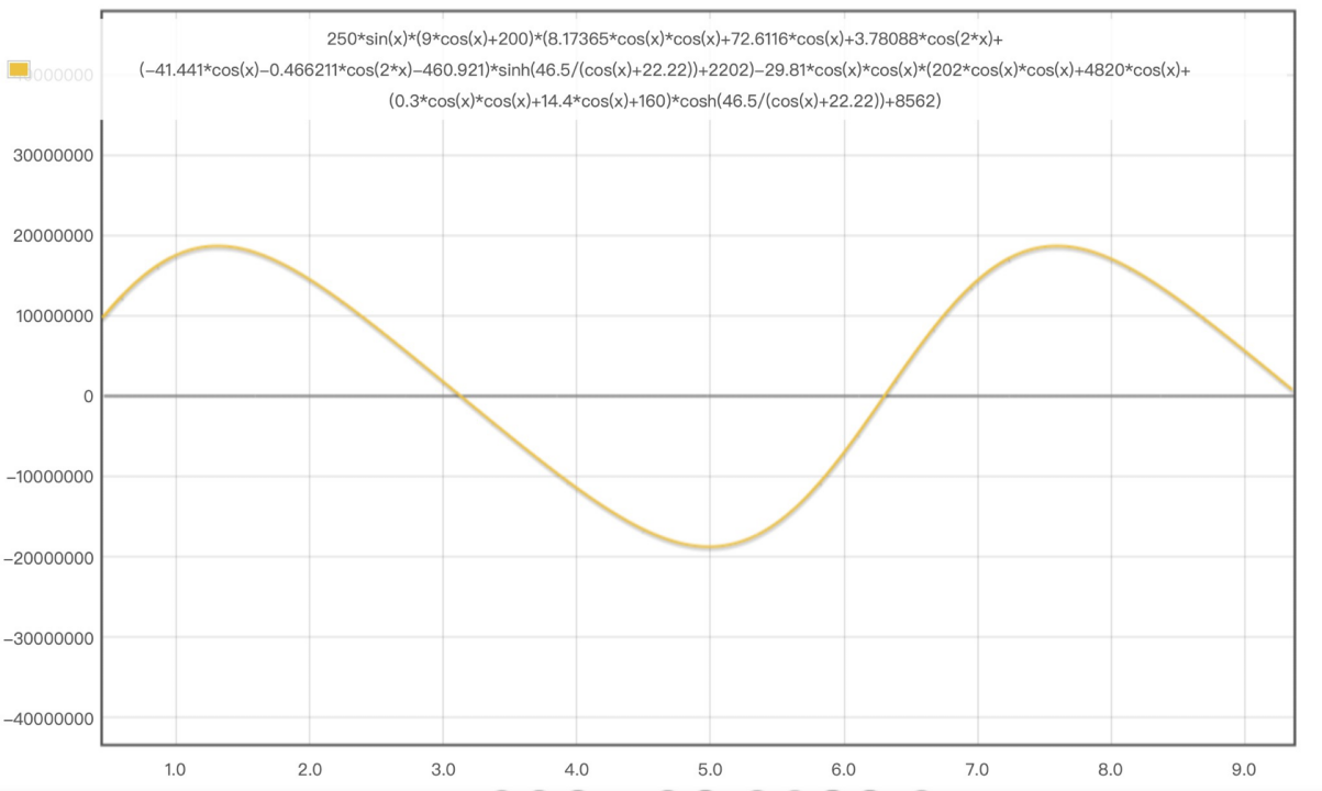
Figure 2. Morrison force on a single foundation, Ftotal=16F.
1.8 Economic evaluation
The economic budget includes not only the cost of each part of the equipment, but also the cost of the construction site, the supply of electricity and water, the installation of the platform, the welding of the trusses, the construction of the hemispherical foundation and its rectangular platform, the transport of the fan blades and the installation of the fan, which accounts for about ten percent of the total cost.
The results of cost calculation can be seen in the table 6.
Table 6. Cost calculation.
Device name | Number | Unit price (RMB) | Price | |
Wind turbines | 8 | 13945590 | 111564720 | |
Smartflower Photovoltaic panels | 767 | 10582 | 811.66 | |
Tesla charging stations | 767 | 4300 | 3298100 | |
Hemisphere Basics (DH32) | 2336.52 kg | 4200/t | 10270 | |
Platform | 21636.27 kg | 4200/t | 103850 | |
Trusses | 51253.44 kg | 3820/t | 195790 | |
C30 concrete | 35342917.35 kg | 1480/t | 52307520 | |
Manpower building costs | 15000000 | |||
Total price | 189696830 | |||
Cost per kw | 13120 | |||
2. Discussion
There are a number of problems with the current development of offshore wind power. The first point is that the operation of the equipment in the wind farm after construction can have a certain impact on that sea area, while the construction waste from the wind power equipment can pollute the marine environment and affect the normal survival of marine life. The noise from the movement of the blades can disturb birds [9]. The second is that most offshore floating structures are not very stable due to the many complex external forces they receive such as wave loads, wind loads, etc. The third is the shortage of Western Energy construction equipment and the lack of key equipment [10]. The new offshore wind and photovoltaic integrated structure mentioned above has good stability and will remain stable under huge wave loads and wind forces. And the integration of wind and photovoltaics improves the power generation efficiency of the platform, thus reducing costs. The whole structure is simple to assemble, and the equipment purchase route is clear, making it highly feasible.
4. Conclusion
This research completes the combination of offshore wind power and photovoltaic power-based design. The research is conducted from three aspects: functional, security and economy. Functionally, the floating structure realizes the combination of offshore wind power and photovoltaic to maximize the generating efficiency of the platform. At the same time, the innovative Smartflower photovoltaic power generation equipment also enhances the generating efficiency. In terms of security, the stability and load calculation is proceeded to check security: At the stability aspect, the initial metacentric height is greater than 0, so the floating structure has a splendid stability. As for the load calculation, the load calculation is divided into wind load calculation and wave load calculation. The two results of the calculations are both reasonable. The structure can stay stable in known sea conditions. At the economic aspect: in consideration of the price of various components of the structure and manpower construction cost, the total price is of great rationality. From the above perspective, the floating structure has favourable feasibility. This research offers a feasible and innovative scheme to green energy utilization. In further, the effect of noise from the movement of the blades should be studied. And the lack of significant energy equipment is also a problem for the utilization of this power generation system.
References
[1]. Miao Jun,Ma Wenyong. Construction of integrated solution capacity for floating offshore wind p-ower [J]. Solar Energy,2018,(06):46-48.
[2]. Wang Fuqiang,Hao Jungang,Li Shuai,Ren Yajun,Xie Yuetao,Zhang Buen. Key technologies and development trend of floating offshore wind power[J]. Hydroelectricity,2022,48(10):9-12+117.
[3]. Song Bo, Zhou Heng, Wang Daoyong. New foundation design for floating offshore wind power tower[J]. Ship and sea engineering,2021,50(05):128-131+137.
[4]. Ren Fengxuan,Wang Zhongyong. Intelligent adaptive tracking control for sunflower-type high-e-fficiency photovoltaic power generation[J]. Electronic Devices,2019,42(06):1421-1427.
[5]. Song Zhaobo. Structure design and dynamic characteristics study of large floating offshore fan p-latform. Dalian University of Technology,2022.
[6]. Qiu Peng, He Yuzhang, Zhang Mingming. Research on high prediction method of ship initial sta-bility[J].Shipping supplies and markets,2021,29(09):46-48.
[7]. Shi Peiyu,Yuan Linxin. Initial metacentric height and initial stability height -- "Nautical technical-l terms" refers to the fault[J].Transporation Standardization,2003,(01):53.
[8]. Lu Tao.Carbon fibre solar capture system efficiency increased by 40%[J].Shandong ceramics,2015(4):30-30.
[9]. Zhang Yuchao, Xu Pengcheng. Study on the development of offshore wind power and environm-ental issues in China[J]. China's strategic emerging industries,2017,(20):22.
[10]. Xu Liguo,Ren Jianyu. Current situation and outlook of offshore wind power generation[J]. Port Technology,2022,59(06):45-48.
Cite this article
Zhang,H.;Su,C. (2023). Mechanical property analysis and rationality study of new offshore floating wind power photovoltaic structure. Applied and Computational Engineering,9,107-113.
Data availability
The datasets used and/or analyzed during the current study will be available from the authors upon reasonable request.
Disclaimer/Publisher's Note
The statements, opinions and data contained in all publications are solely those of the individual author(s) and contributor(s) and not of EWA Publishing and/or the editor(s). EWA Publishing and/or the editor(s) disclaim responsibility for any injury to people or property resulting from any ideas, methods, instructions or products referred to in the content.
About volume
Volume title: Proceedings of the 2023 International Conference on Mechatronics and Smart Systems
© 2024 by the author(s). Licensee EWA Publishing, Oxford, UK. This article is an open access article distributed under the terms and
conditions of the Creative Commons Attribution (CC BY) license. Authors who
publish this series agree to the following terms:
1. Authors retain copyright and grant the series right of first publication with the work simultaneously licensed under a Creative Commons
Attribution License that allows others to share the work with an acknowledgment of the work's authorship and initial publication in this
series.
2. Authors are able to enter into separate, additional contractual arrangements for the non-exclusive distribution of the series's published
version of the work (e.g., post it to an institutional repository or publish it in a book), with an acknowledgment of its initial
publication in this series.
3. Authors are permitted and encouraged to post their work online (e.g., in institutional repositories or on their website) prior to and
during the submission process, as it can lead to productive exchanges, as well as earlier and greater citation of published work (See
Open access policy for details).
References
[1]. Miao Jun,Ma Wenyong. Construction of integrated solution capacity for floating offshore wind p-ower [J]. Solar Energy,2018,(06):46-48.
[2]. Wang Fuqiang,Hao Jungang,Li Shuai,Ren Yajun,Xie Yuetao,Zhang Buen. Key technologies and development trend of floating offshore wind power[J]. Hydroelectricity,2022,48(10):9-12+117.
[3]. Song Bo, Zhou Heng, Wang Daoyong. New foundation design for floating offshore wind power tower[J]. Ship and sea engineering,2021,50(05):128-131+137.
[4]. Ren Fengxuan,Wang Zhongyong. Intelligent adaptive tracking control for sunflower-type high-e-fficiency photovoltaic power generation[J]. Electronic Devices,2019,42(06):1421-1427.
[5]. Song Zhaobo. Structure design and dynamic characteristics study of large floating offshore fan p-latform. Dalian University of Technology,2022.
[6]. Qiu Peng, He Yuzhang, Zhang Mingming. Research on high prediction method of ship initial sta-bility[J].Shipping supplies and markets,2021,29(09):46-48.
[7]. Shi Peiyu,Yuan Linxin. Initial metacentric height and initial stability height -- "Nautical technical-l terms" refers to the fault[J].Transporation Standardization,2003,(01):53.
[8]. Lu Tao.Carbon fibre solar capture system efficiency increased by 40%[J].Shandong ceramics,2015(4):30-30.
[9]. Zhang Yuchao, Xu Pengcheng. Study on the development of offshore wind power and environm-ental issues in China[J]. China's strategic emerging industries,2017,(20):22.
[10]. Xu Liguo,Ren Jianyu. Current situation and outlook of offshore wind power generation[J]. Port Technology,2022,59(06):45-48.