


1. Introduction
With the continuous development of mechanical automation technology, robots have taken over human work in many fields. As potted plants in public places have the characteristics of dispersion and large quantity, they can’t be watered by large-scale irrigation. Instead of using human labor, applying robots to do the work seems to be a sensible choice. However, according to the current research, indoor watering robots are seldom designed, though there are many productions in irrigation robots for agriculture.
LYU designs a mobile watering robot, which can automatically move based on the default way, supplying the potted plants with water[1]. It is also able to improve watering efficiency and reduce the intensity of manual spraying, so the use of human resources is reduced. The design includes the kinematics analysis, the obtained motion equations, and a rough 3D model.
Liu comes up with the design of a mobile flower-watering robot based on ROS(Robot Operating System)[2]. It is equipped with the function of SLAM(Simultaneous Localization and Mapping and machine vision). The robot can also plan its path automatically and navigate autonomously. These designs are quite complicated, involving complex calculations, precise instruments and relatively high costs, so the promotion is not beneficial.
Correll implemented a horticultural system that works autonomously mainly in indoor environments or urban areas[3]. The design is quite perfect, but it can hardly be adopted in public places with a lot of people.
Secuianu presents an autonomous moving robot using computer vision[4]. The robot is a good platform for indoor plant watering, but the watering function hasn’t been added to the robot.
Huang puts forward the design of a visual indoor flower-watering robot[5]. Design thoughts, basic structures, and working principles are shown in his article, but it doesn’t provide a specific design.
Under the circumstances, a scheme of an Arduino-based robot for indoor plant watering through software design and hardware experiments is put forward, intended to provide new ideas and methods for solving this problem. This design is proposed only to achieve certain functions, such as tracking, detecting plants and spraying water. So its realization will be relatively economical.
2. Analysis of the working environment
In this paper, the working environment of the robot is an office of an enterprise. Some potted plants are placed inside the building, alternating on both sides of the aisle at a distance. Since the control strategy through a model requires high accuracy of the motion of the robot, the strategy is abandoned.
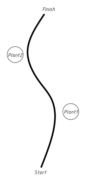
The schematic working environment is shown in Figure 1. The robot will follow a predetermined path from the beginning to the end, and it will water the plants when they're close enough. Those plants are various in kind and size, so the robot is required to take different actions when it waters the plant. Two plants are set up here to simulate the actual situation. The black line here is used for robot navigation. It should be smooth on the turnings, and the relatively straight part ought to be direct at the following plant.
| Figure 1. Schematic drawing of the working environment. |
3. Basic functions
To finish the watering work, the robot has three basic functions: tracking, distance measurement and spraying water. These functions are realized by Arduino code, electronic components and mechanical structures. Extra abilities can also be added to the robot, as there is still much space for further improvement.
3.1. Tracking
With infrared sensors, the robot is able to detect the black line on the ground. Some wheeled mobile robots have the configuration of wheels arranged at the four corners of a rectangular plane[6]. The robots’ two rear wheels are driven at differential speeds and the two front wheels steer synchronously. The layout used in this article applies a similar differential steering strategy, with two universal wheels in the front of the main body and two motor-driven driving wheels in the back. Figure 2 provides a visualization of the principles of route-tracking. When the robot finds itself too far from the line, it will turn in the corresponding direction to move close to the line. The specific method is illustrated in the program part below detailedly.
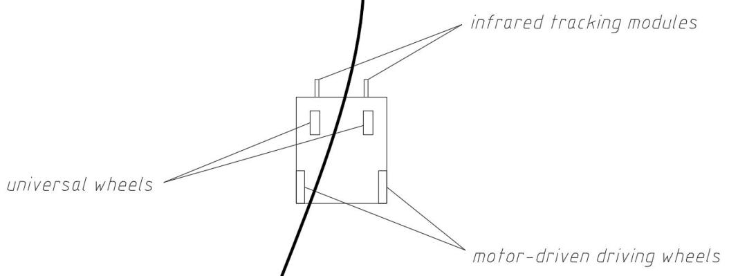
Figure 2. Principles of route-tracking.
3.2. Distance measurement
With the ultrasonic sensors on the front and the rear of the robot, the distance between the plant and itself is detected. After the data is gained, the robot will take different actions according to the result. The layout of ultrasonic sensors is depicted in Figure 3. If the plant is close enough to the front ultrasonic sensor, the robot will switch to the watering mode. And it will start moving when the watering process is finished.
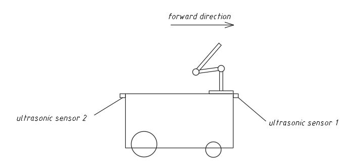
Figure 3. Layout of ultrasonic sensors.
3.3. Spraying water
The robot should be able to carry a sufficient amount of water to meet the need for watering numerous plants. In addition, according to the type of plant, it chooses the amount of water sprayed and the position of its nozzle. To avoid making the surroundings wet, the water will be sprayed in a current state, instead of a fog state. The above actions will be performed by a series of electrical components. The layout of the components used for spraying water is shown in Figure 4.
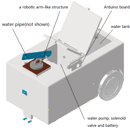
Figure 4. Layout of components used for spraying water.
4. Compositions of the robot
As the watering robot needs to complete complicated work, it includes several parts, which can be broadly divided into two categories, hardware and program. The following sections describe the performance of used components, the reasons for their selections and critical paragraphs of the code.
4.1. Hardware
4.1.1. Motor system. The base is an 800 × 450 × 350 box. Several slots are dug for the installation of different components and a water tank. A hole leads from the tank to the side of a structure that looks like a robotic arm. The hole holds a hose for water conduction. Water goes through the pipe to the nozzle on the end of the mechanical structure. Two stepper motors and two fixed wheels are placed in the back of the base, while two universal wheels are placed in the front. This layout enables differential steering. Differential steering has a small turning radius, so it is more suitable for indoor robots in the working environment. Figure 5 provides a visualization of the motor system of the robot.
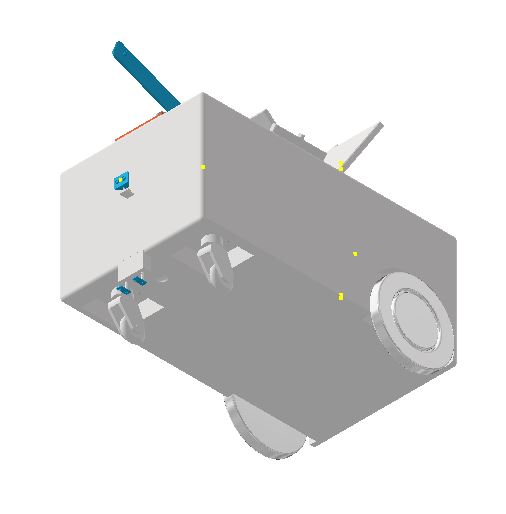
Figure 5. Motor system of watering robot.
4.1.2. Control system. An Arduino Uno board is used in this project. The Arduino board has a low price with many ports and good stability. It can reduce costs while meeting all demands. The infrared tracking modules can distinguish between black and other colors according to the light reflected by the ground.
When working, the infrared tracking module of TCRT5000 continuously emits infrared rays with a wavelength of 950nm[7]. When the emitted infrared rays are not reflected back by obstacles or the reflection intensity is insufficient, the photosensitive transistor does not work. When the infrared reflection intensity is sufficient and is received by the photosensitive transistor at the same time, the photosensitive transistor is in a working state, providing the output. Two infrared tracking modules are placed on the left and right sides of the central axis and the Arduino board can confirm whether the robot is to the left of the line or the right. For example, if the left sensor detects the black line while the right one doesn’t, it means that the robot is to the right of the line. Two ultrasonic sensors are placed on the front and the rear of the robot to measure distances. The measurements will determine what the robot will do next. Ultrasonic sensors emit and receive high-frequency ultrasonic waves[8]. The distance is calculated with a formula using the propagation time of the ultrasonic waves. The principle behind distance measurement with sonar sensors is shown in Figure 6.
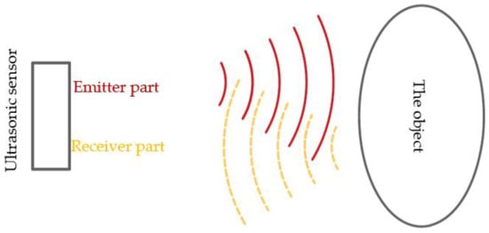
Figure 6. The principle of distance measurement with sonar sensors[8].
A force-sensitive resistor is installed on the bottom of the water tank to measure the weight of the water. When the weight of the water reaches a predetermined level, subsequent operations will begin.
4.1.3. Watering system. A water pump and a solenoid valve cooperate with each other to regulate the water flow. They are in parallel, so a relay can be used to control both of them. In order to coordinate the water supply system with the whole one, the relay receives signals from the Arduino board. After the robotic arm-like structure reaches the right position, the pump and the valve start working, the specific mechanical structure acts like a robotic arm, and a water pipe is held by this structure to keep the nozzle in place. Figure 7 provides a visualization of the specific structure driven by three servos.
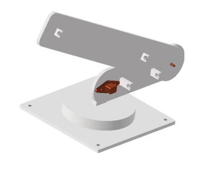
Figure 7. Robotic arm-like structure of watering system.
4.2. Program
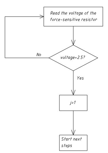
The program is completed in Arduino IDE. The code includes three critical parts, respectively controlling distance measurement, tracking, and water spraying. At the beginning of the loop, an indicator of the weight of water, j, is set. When j turns into 1, it means the water tank is fully loaded, and the following code starts running then. The starting condition is shown in Figure 8.
| Figure 8. Starting condition. |
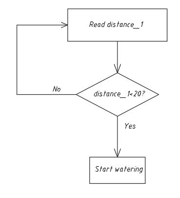
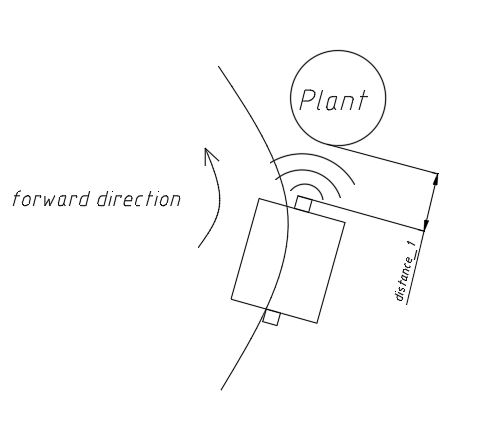
4.2.1. Distance measurement. The two ultrasonic sensors keep measuring the distances. The variable distance_1 represents the distance measured by the former sensor. The distance is calculated with a formula. The relevant code is shown below. When distance_1 is lower than a configured level(for example 20), the robot stops moving and gets ready for the process of watering. The condition to start watering is shown in Figure 9. Figure 10 provides a visualization of the position of distance_1.
|
|
Figure 9. Condition to start watering. | Figure 10. Position of distance_1. |
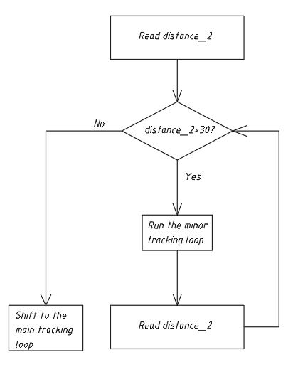
When the watering process is finished, distance_2(the distance measured by the rear ultrasonic sensor), is the index determining the movement of the wheels. If the rear distance is longer than the default level, the tracking code in the minor while loop operates. The code makes the robot keeps moving until distance_2 is smaller than the predetermined value. Then the robot exits this loop. If distance_2 is lower than the configured value, it represents that the robot has already passed the curve. Finally, the program shifts to the main tracking loop, moving on to the next plant.
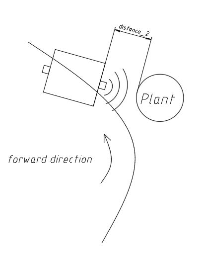
If distance_2 and the relevant minor while loop are not used here, the robot will stop just in front of the plant, for distance_1 is always at a low level. The usage of distance_2 is shown in Figure 11. The position of distance_2 is depicted in Figure 12.
|
|
Figure 11. Usage of distance_2. | Figure 12. Position of distance_2. |
4.2.2. Tracking. The robot uses infrared sensors to emit infrared signals to the ground. A black and white clear track line is placed on the ground. In the process of tracking, if the floor is white, the robot constantly receives reflected infrared light[9]. If the black line is encountered, the infrared light is absorbed and the receiving tube on the tracking vehicle cannot receive the infrared light signal.
The result is used to confirm its position relative to the line. If one sensor sends a high-level signal, while the other sends a low-level one, it means that the robot is on the side of the sensor that sends the low-level signal. When the robot finds itself too far from the line, it will turn in the corresponding direction to move close to the line. And then the robot tends to be in the correct position. The principles of tracking are shown in Figure 13.
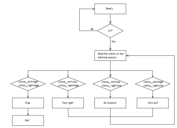
Figure 13. Principles of tracking.
4.2.3. Water spraying. When the Arduino board sends a high-level signal to the relay, the water pump and the solenoid valve start working, allowing water to go through the pipe. With a case structure, the robot is able to correspond to two different types of plants and cease in the end.
During the process, servo motors start working first to make the specific structure in the right position with servo.write code. After that, the water pump and the solenoid valve start working as the board sends a high-level signal, and then a certain amount of water is sprayed from the nozzle. At the end of the watering process, the specific structure is reset to the default position with a stacked reset function. The way of selecting the watering mode is shown in Figure 14.
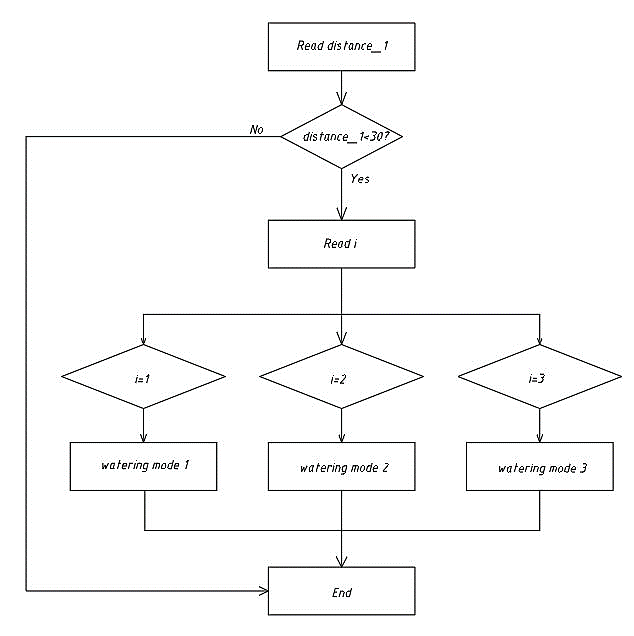
Figure 14. Watering mode selection.
5. Verification
In order to verify whether the design is feasible, an experimental circuit is set with several components. The circuit is used for testing the program structure and the basic functions. The circuit isn’t the complete one placed on the robot, and the program is not the one actually used as well. A photoresistor is used here to represent the force-sensitive resistor. The photoresistor is a photoelectric device made of photoconductive material without polarity, and the photoconductive effect will cause the resistivity of the object to change[10]. A LED light is used to indicate whether the tracking part of the code works correctly. The circuit diagram is shown in Figure 15.
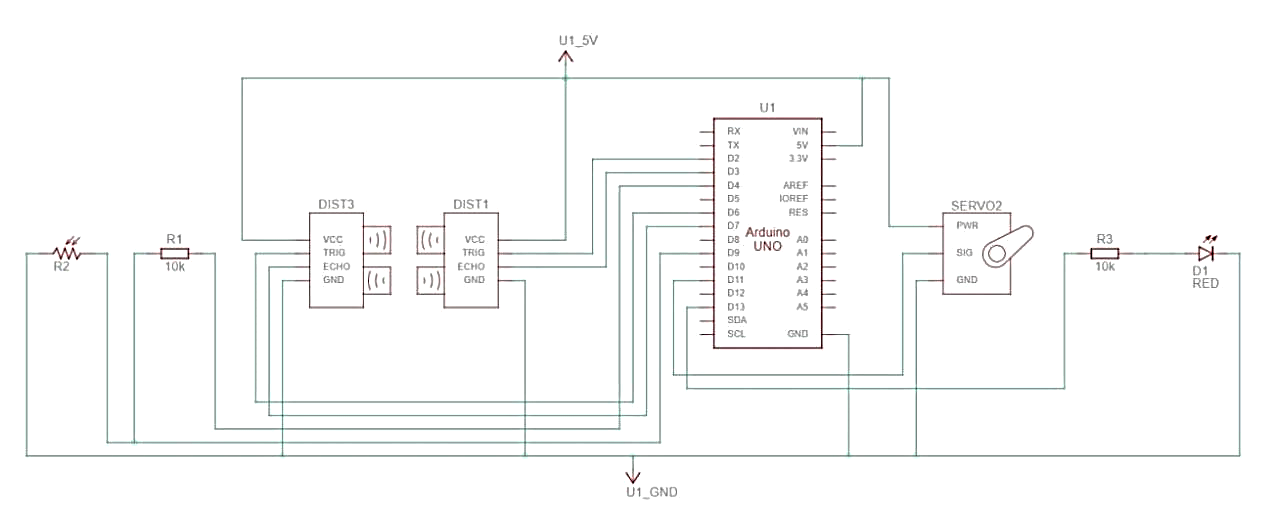
Figure 15. Circuit diagram of verification circuit.
At first, the light on the photoresistor, representing a plant is close enough to the robot. Next, the LED starts to flicker, while the servo begins to operate. When an obstacle is placed close enough to the rear ultrasonic sensor, the servo stops working and an indicator is shown on the serial port monitor, confirming the code runs well. Finally, it returns to the initial loop, and the next loop can work correctly as well. After the verification, the experimental circuit illustrates that the program and the circuit are feasible. Up to now, there has been much space for further improvement. As too many components share the same 5V power source of the Arduino board, some failure may be caused by occasional signal interferences according to practical experience. The code used to drive servo motors and measure distance can be optimized in the future, because some errors may happen if parameters are not configured properly in actual use. Figure 16 gives a visualization of the physical circuit.
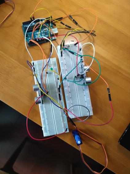
Figure 16. Physical drawing of verification circuit.
6. Conclusion
As many potted plants are placed at long distances from each other in public areas, watering them leads to much manpower consumption, while it’s appropriate to use robots. Targeting watering indoor plants in public areas, an Arduino-based watering robot is designed in this paper. It includes three main systems, the power system, the watering system and the control system composed of electronic components and mechanical structures. The robot adopts a differential steering strategy, obtains environmental information through a variety of sensors, and uses a robotic arm-like structure to accomplish accurate watering. Through the test circuit, the general idea of the design is demonstrated to be feasible. This paper provides a valuable variant for watering indoor plants.
References
[1]. LYU P, Gao X and Luo D et al. 2021 Ordnance Industry Automation 2021 40 42–46
[2]. Liu J and Jiao S 2022 Modern Electronics Technique 45 122–126
[3]. Correll N, Arechiga N and Bolger A et al. 2010 Intel Serv Robotics 3 219–232
[4]. Secuianu F, Mihai C, Vulpe A and Lupu C 2017 18th Int. Carpathian Control Conf. (Sinaia) pp 246–251
[5]. Huang Y 2019 China Southern Agricultural Machinery 50 24
[6]. Cao Q, Zhang L 2012 Wheeled Autonomous Mobile Robot (Shanghai: Shanghai Jiao Tong University Press) p 19
[7]. Li S, Huang H and Tang J 2020 Practical Electronics 405 18–20
[8]. Komarizadehasl S, Mobaraki B, Ma H, Lozano-Galant J and Turmo J 2022 Applied Sciences 12 3186
[9]. Huang Y, Zhao C, Xv B and Liu M 2017 Laboratory Science 20 51–53
[10]. Zhang Q and Ji J 2018 Sensor and Automatic Detecting Technology (Beijing: China Machine Press) pp 111–112
Cite this article
Cai,Y. (2023). Design of Arduino-based wheeled robot for plant-watering in public places. Applied and Computational Engineering,10,1-10.
Data availability
The datasets used and/or analyzed during the current study will be available from the authors upon reasonable request.
Disclaimer/Publisher's Note
The statements, opinions and data contained in all publications are solely those of the individual author(s) and contributor(s) and not of EWA Publishing and/or the editor(s). EWA Publishing and/or the editor(s) disclaim responsibility for any injury to people or property resulting from any ideas, methods, instructions or products referred to in the content.
About volume
Volume title: Proceedings of the 2023 International Conference on Mechatronics and Smart Systems
© 2024 by the author(s). Licensee EWA Publishing, Oxford, UK. This article is an open access article distributed under the terms and
conditions of the Creative Commons Attribution (CC BY) license. Authors who
publish this series agree to the following terms:
1. Authors retain copyright and grant the series right of first publication with the work simultaneously licensed under a Creative Commons
Attribution License that allows others to share the work with an acknowledgment of the work's authorship and initial publication in this
series.
2. Authors are able to enter into separate, additional contractual arrangements for the non-exclusive distribution of the series's published
version of the work (e.g., post it to an institutional repository or publish it in a book), with an acknowledgment of its initial
publication in this series.
3. Authors are permitted and encouraged to post their work online (e.g., in institutional repositories or on their website) prior to and
during the submission process, as it can lead to productive exchanges, as well as earlier and greater citation of published work (See
Open access policy for details).
References
[1]. LYU P, Gao X and Luo D et al. 2021 Ordnance Industry Automation 2021 40 42–46
[2]. Liu J and Jiao S 2022 Modern Electronics Technique 45 122–126
[3]. Correll N, Arechiga N and Bolger A et al. 2010 Intel Serv Robotics 3 219–232
[4]. Secuianu F, Mihai C, Vulpe A and Lupu C 2017 18th Int. Carpathian Control Conf. (Sinaia) pp 246–251
[5]. Huang Y 2019 China Southern Agricultural Machinery 50 24
[6]. Cao Q, Zhang L 2012 Wheeled Autonomous Mobile Robot (Shanghai: Shanghai Jiao Tong University Press) p 19
[7]. Li S, Huang H and Tang J 2020 Practical Electronics 405 18–20
[8]. Komarizadehasl S, Mobaraki B, Ma H, Lozano-Galant J and Turmo J 2022 Applied Sciences 12 3186
[9]. Huang Y, Zhao C, Xv B and Liu M 2017 Laboratory Science 20 51–53
[10]. Zhang Q and Ji J 2018 Sensor and Automatic Detecting Technology (Beijing: China Machine Press) pp 111–112