


Significant impacts of injection parameters on marine diesel engines
Introduction
As the heart of a diesel engine, many research institutions and companies have refined the fuel injection system over the years. The overall engine performance and the polluting emission mainly depend on the combustion quality, which is largely influenced by the arrangement of the fuel-air mixture. The most important function of the fuel injection system is to deliver fuel oil into the cylinder with a controllable quantity, timing, and flow rate and achieve a fine and uniformly distributed spray. The injection system will be more complex when designed for marine diesel engines than for vehicle diesel engines because of marine diesel' high single-cylinder power and because they are required to burn fuel oil in a fairly large bore cylinder uniformly. Also, the system needs to be operated on inferior fuels such as heavy fuel oil, which can have a viscosity of up to 380 cST/50 ˚C [1].
Moreover, the injection system must have some special features: their injection timing needs to be adjusted over a large range between normal and reverse operation, the fuel injection to a certain cylinder needs to be stopped during a cut-off operation, the fuel supply must be stopped during air-start or emergencies without adjusting the fuel rack or disengaging the pump transmission system. With the increasingly more restrictive IMO rules and the background of the energy crisis, the fuel injection system needs to be refined to obtain more uniform and complete combustion in the cylinder. The injection parameters are quite important in marine diesel engines. Improper injection timing can lead to unpleasant engine performance or even failure, such as unsuccessfully reverse operation, cracks on the piston crown, piston ring and cylinder liner premature wear, exhaust valve and valve seat corrosion and scavenging room fire. Proper injection pressure will match the fuel spray to the combustion chamber, while too low and too high injection pressure will increase the concentration of the fuel near the atomizer and decrease the efficiency. Over the past century, MAN-B&W, SULZER, OXFORD, MITSUBISHI-KOBE and many other main engine builders have developed many fuel injection systems, some performing very well. Some of these are spill valve regulated fuel injection systems, MAN-B&W MC fuel injection systems, and RT-flex electric controlled systems.
MAN-B&W MC engine's fuel injection system mechanism
The working principle
On 2-stroke marine diesel engines, the injection system requirement differs from that on a small-size engine. The load varies from anchorage slow to emergency full, the engine needs to be operated reversely, the rotation speed is very low [could reach 14 rpm], and the bore size is quite large [980 mm], so it is hard to acquire a strong air-flow to atomize the fuel. The characteristics mentioned make transplanting a generalized injection system to marine diesel impossible. In 1981, MAN-B&W introduced the well-known MC series marine diesel engines, which feature a specially designed injection system [2]. The MAN-B&W MC injection system belongs to the jerk pump type direct injection system but with some special details. The system features the following parts: fuel pump driving camshaft, plunger assembly, suction valve, puncture valve, double-layered high-pressure fuel pipe and the fuel valve. The working principle will be briefly introduced down below.
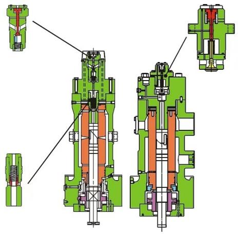
Figure 1. The MC injection pump [3].
The whole injection pump assembly is shown in Figure 1. The left features separated suction and puncture valves, while the right has an integrated suction-puncture valve. In the left picture, the plunger, barrel, fuel suction valve and puncture valve can be seen from the bottom to the top. During the fuel intake stroke, the plunger is located at the top of its full stroke, and after that, it will be pushed down by the spring. As the volume above the plunger gradually increases, the pressure in the chamber decreases. When the pressure in the chamber reaches a certain value, the oil supply line pressure will overcome the spring force of the fuel suction valve, and the fuel will be inhaled into the pump. In the next procedure, the helix groove in the plunger will coincide with the spill port in the barrel, and now the fuel will enter the volume above the plunger through the spill port. At the end of this procedure, the plunger will reach its lowest position. In the following procedure, the follower, rolling on the cam, actuates the plunger to move upward against the spring force and the oil pressure. After the upper edge of the plunger closes the spill port, the fuel pressure will start to build up in the volume above the plunger. At this point, the spring inside has closed the fuel suction valve. The high-pressure wave will then travel through the pipe, leading to the fuel valve on the cylinder head. After the high-pressure wave reaches the fuel valve, it will actuate the non-return valve and then reach the injection nozzle spindle valve. With the pressure continuously increasing, the valve spindle will finally be lifted, and the fuel oil will be sprayed and finely atomized under high pressure.
The injection pump assembly
As mentioned above, the injection pump on MC series engines is a jerk pump but with some conversions. The most noticeable improvement of the MC engine fuel system is its VIT [Variable Injection Timing] injection pump. Under high-load operation, the start of the injection needs to be advanced to reduce the risk of after-combustion. In a normal jerk pump, the start of the injection is related to the position of the spill port, and since the barrel is fixed, the injection timing cannot be changed. In a VIT pump, a pitch thread is machined on the barrel, and a sleeve is used to control the axial position of the barrel. As shown in Figure 2, a timing rack controls the start of the injection, while another fuel rack controls the amount of fuel injected. Thus, the timing and the fuel quantity are controlled independently [4].
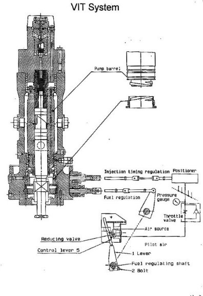
Figure 2. The MC VIT pump [5].
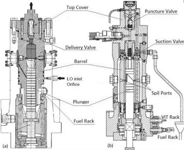
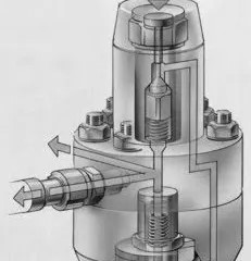
Figure 3. The puncture valve [6].
In the MC injection pump, a puncture valve is shown in Figure 3, located on the pump cover. The main purpose of the puncture valve is to stop fuel injection independently with the fuel rack position. This operation is quite important for marine diesel engines. During the air start procedure, reversing procedure or emergency stop situation [such as when fuel leakage has been detected in the double-layer high-pressure fuel pipe], pneumatic air pressure will enter the puncture valve, and the high-pressure fuel will be returned to the pump housing. As a result, the fuel injection is stopped.
Since the engine is required to burn heavy fuel oil, the whole injection system needs to be heated to lower the fuel viscosity. The system uses heated fuel oil to keep the injection components' temperature high. It is impossible to keep the temperature high by just relying on the amount of fuel that the engine uses. As a result, the system employed the so-called circulating fuel: the fuel can flow through the whole injection system continuously even the engine is stopped. To obtain this ability, the injection pump has a circulation port from which the hot fuel can be discharged [7].
The fuel valve
The MC series engines use a specially designed fuel valve called the slide-valve type fuel valve. This is shown in Figure 4. The slide-valve fuel valve assembly contains three main components: the non-return valve, the slide-valve and the atomizer.
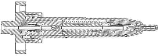
Figure 4. MC slide-valve type fuel valve [8].
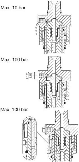
Figure 5. Non-return valve actuating process [9].
The slide-valve configuration is to solve the problem of fuel after-dripping. The volume inside the nozzle tip causes after-dripping: the remaining fuel inside the sac will be heated by the combustion gas and expand, which results in their flowing out. The after-dripped fuel is delivered under very low pressure, so it cannot be finely atomized. This will result in high CO and HC emissions. Figure 6 shows that by applying this valve, the sac volume of the atomizer can be reduced from 1990 mm³ to 520 mm³. By reducing this sac volume, the NOx emission under 90% load condition can be reduced from 1594 ppm to 1232 ppm, and the soot buildup in the cylinder can also be reduced. Using the MC system, some old marine diesel engines can be converted to meet the TierⅠemission regulation [10]. The injection pressure varies with the load in a mechanically driven injection pump. Increasing the fuel valve opening pressure in relevance to the injection pressure is wise. This is done on the MC fuel valve using a variable thrust piece shown in Figure 7. Under high pressure, the load spring will be compressed to increase the valve opening pressure.
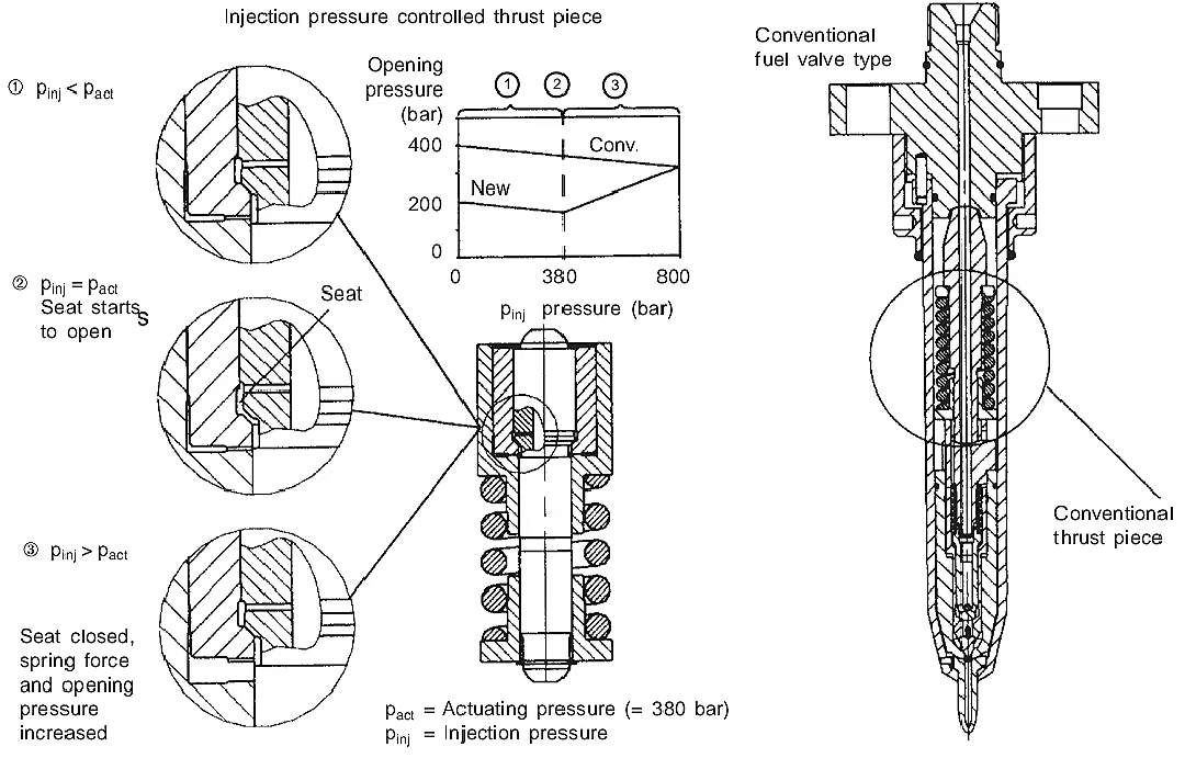
Figure 6. The comparison between a general fuel valve and a slide-valve type fuel valve [10].
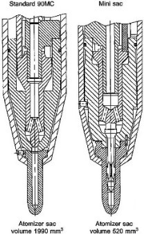
Figure 7. Injection pressure controlled thrust piece [11].
In a low-speed two-stroke propulsion system, the main engine is directly coupled to the propeller, so the main engine must be operated reversely in an astern situation. The injection timing needs to be adjusted concerning the direction of rotation. This kind of operation is obtained with a specially designed fuel cam. As shown in Figure 8, the fuel cam has a symmetry shape. When the engine's rotation needs to be changed, a pneumatically operated actuator will change the position of the injection pump roller. As a result, the injection timing is changed. Together with the VIT system, the main engine can be operated reversely.
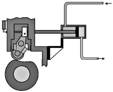
Figure 8. The reversible fuel injection pump driving mechanism [12].
Ways of influencing the engine performance
Advanced injection timing
If the injection happens earlier than the engine builder recommends, it is called advanced injection timing. Because the fuel ignites in a gradually decreased combustion chamber volume, the temperature and pressure will be higher than normal.
Higher combustion pressure also means more power can be delivered. Rather than retarded injection, advanced injection allows for a larger expansion ratio which means the efficiency will be higher. This is shown in Figure 9.
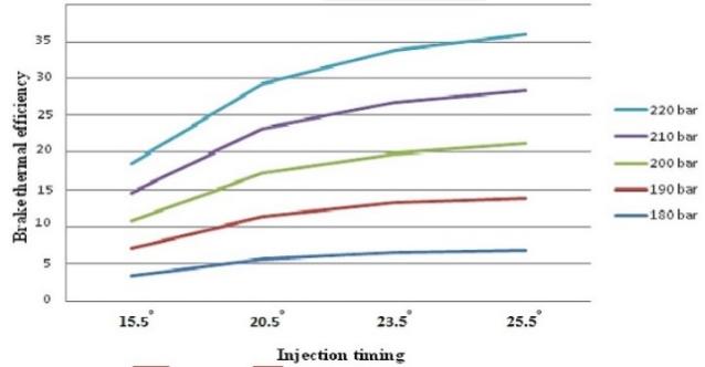
Figure 9. Break thermal efficiency as the function of injection timing and pressure [7].
With the help of free radicals such as O, N, H, OH and CH, which are mostly formed during the combustion process, the Oxygen and Nitrogen from the air and fuel will form the NOx under high temperatures by following the under equations [5]:
O + N2 ↔︎ NO + N (1)
N + O2 ↔︎ NO + O (2)
N + OH ↔︎ NO + H (3)
CH + N2 ↔︎ HCN + N, N + O2 ↔︎ NO + O (4)
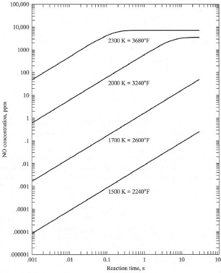
Figure 10. NO concentration as the function of time and combustion temperature [7].
Figure 10 shows that the higher the combustion temperature, the higher the concentration of NOx will be. The concentration of NOx is in direct proportion to the reaction time until it saturates. If the engine has an advanced injection timing, the combustion gas will be trapped in the combustion chamber under a higher than usual temperature, and the reaction time will also be longer. This will generate more NOx emissions, as shown in Figure 11.
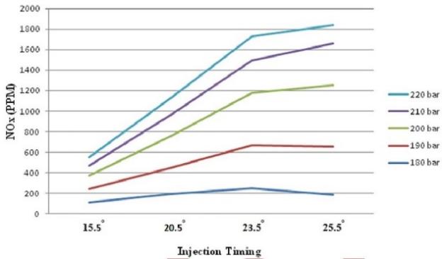
Figure 11. NOx concentration as the function of injection timing and pressure [7].
High peak combustion temperature can introduce too much heat stress onto the piston crown. Since the piston is cooled by the circulation of lubricating oil inside the piston crown, high temperature will break down the lube oil, and the carbon soot formed will deposit on the cooling surface. This, in turn, increases the surface heat transfer coefficient, which means insufficient piston cooling and can result in cracks in the piston [7].
Retarded injection timing
As the opposite of advanced injection, retarded injection means the injection happens later than the engine builder recommends. Due to the increasing combustion chamber volume, the pressure and temperature inside the chamber will decrease, thus increasing the ignition delay time.
Since the ignition happens after TDC in this situation, the expansion ratio will be lowered to decrease efficiency. This will result in a higher-than-normal exhaust temperature. Marine diesel fuel can contain up to 3.5% Sulfur. When the sulfates are combined with vanadium and sodium, it will form a low melting point corrosive compound which can ruin the sealing area of the exhaust valve [1].
With the longer ignition delay time, the fuel will be exposed to high temperatures over a longer period, thus increasing the possibility of cracking. This will lead to visible black smoke from the exhaust. Soot may condense on the combustion chamber components and the turbocharger. While the fuel does not have enough time to burn, the exhaust will take some of the remaining HC and CO.
Most noticeably, under the retarded injection situation, the scavenging room fire may happen. This is because some unburnt fuel and sparks caused by the soot may enter the scavenging room during the exhaust process. They will initiate the fire when they meet the fresh air and oily condition inside the scavenging room. As mentioned before, an overheated piston may suffer from crown cracks. A similar situation will happen on a retarded injection engine. However, the retarded injection has its advantage: the NOx emission is lowered than normal, as shown in Figure 11.
High injection pressure
With higher injection pressure, the penetration distance of the fuel spray will extend longer than normal, and the fuel will be atomized into finer particles. This improves air utilization and avoids the uneven distribution of the fuel in the combustion chamber, thus achieving lower particle emissions, as seen in Figure 12.
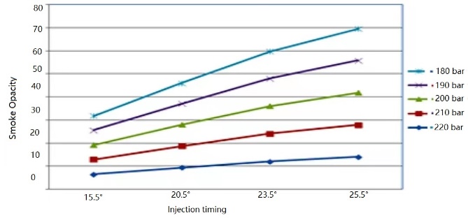
Figure 12. Visible smoke as the function of injection timing and pressure [7].
However, as shown in Figure 11, the NOx emission is also higher with a higher injection pressure. The higher injection pressure gives the fuel droplets more energy to mix with air sufficiently. When the mixture ignites, it will reach a higher peak temperature.
High-pressure injection allows the fuel to be finely atomized. The total surface area is directly proportional to the cube of the diameter. As a result, it will be much easier for the fuel to evaporate and to complete some pre-reactions, reducing the ignition delay time. This can compensate for the retarded injection. It may be a good trial to combine high injection pressure with retarded injection timing to develop the same power while still maintaining the low NOx emission. However, too high injection pressure will accelerate the fuel spray to extreme velocity. Then the spray tip will violently collide with the high-density hot air and be atomized within a short distance [7]. This will decrease the air utilization factor and increase the particular matter emission. In some situations, the fuel can be sprayed onto the cylinder wall, contaminating the lube oil [7].
Low injection pressure
As mentioned above, the fuel oil needs high pressure to be finely atomized. Under low-pressure conditions, the fuel cannot be uniformly distributed in the combustion chamber. This will lead to some areas lacking air while the remaining areas lack fuel. As a result, the combustion will not be sufficient, and the BSFC will rise. Visible smoke, HC, CO emissions and soot buildup will also increase. The abovementioned situations have been shown in Figure 13, Figure 14, Figure 15 and Figure 16 respectively. Like the retarded injection, low injection pressure can lead to scavenging room fire. If an excessive amount of unburnt HC or soot enters the exhaust manifold or the exhaust boiler, it may lead to an explosion, or the boiler coil pipes will melt.
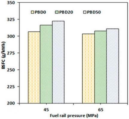
Figure 13. BSFC as the function of injection pressure and torque [11].
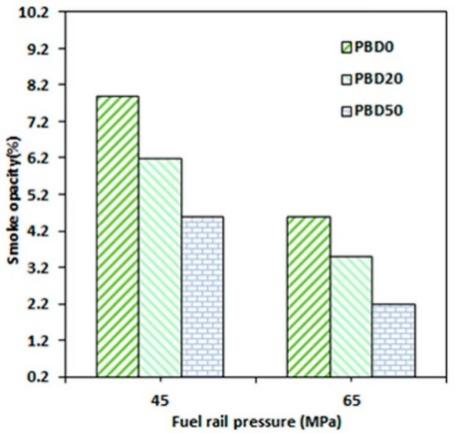
Figure 14. Visible smoke as the function of injection pressure and torque [11].
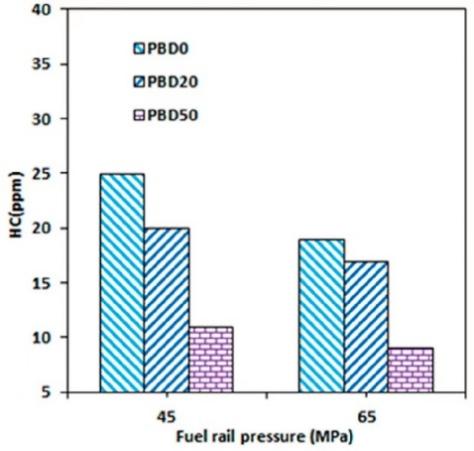
Figure 15. HC emission as the function of injection pressure and torque [11].
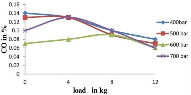
Figure 16. CO emission as the function of injection pressure and load [12].
Conclusion
It can be concluded that the injection timing and pressure on a marine diesel engine greatly influence engine performance and emission. If the increased injection pressure is companied by a finely tuned injection timing, the engine will gain an increased thermal efficiency which means a decreased SFC. Also, the engine's emissions will be greatly improved. It is glad that the MAN-B&W MC series engines have employed the VIT system, which varies the advanced injection timing according to different engine loads and speed conditions. With the growing need for low-emission and low-SFC main engines, the electric controlled injection system will replace the conventional mechanical injection system. The injection pressure and timing can be adjusted independently on the electrically controlled injection system. Also, pre-injection, after-injection and multi-time injection can be employed in different power stages to achieve maximum efficiency. Moreover, to gain a more uniform distribution of the heat of combustion chamber components and to have a more evenly wear of the fuel valves, the 3 fuel valves will take turns working under part-load operation.
Ammonia, methanal and methane engines are very popular these days, all of those fuels have a much higher ignition temperature than conventional diesel fuel, and the combustion is much faster than diesel. They need more precise control over the injection parameters. This could only be achieved by utilizing the electronic control system. The control system can achieve pilot injection and multi-time gas injection. Under fault conditions, the injection system can be shifted to operate on marine diesel again. Advanced electronic control system, such as the WECS-9500, is quite powerful. Together with the real-time cylinder pressure measurement system, it can automatically adjust the injection timing, injection pressure, exhaust valve timing, and auxiliary turbocharger pressure. The research methods also have much progress these days. Ultrafast photography, laser interference measurement and infrared gas analysis have made the research progress more convenient and automatic. As the heart of the diesel engine, the improvement of the fuel injection system will certainly keep on going.
References
References
[1]. International organization for standardization 2010 ISO 8217 2010 Fuel standard for marine distillate fuels
[2]. Doug Woodyard 2003 Pounder's Marine Diesel Engines Eighth edition (Great Britain: Elsevier Butterworth-Heinemann) 372
[3]. Carl-Erik Egeberg, Mikael C. Jensen MAN-B&W February 1997 MAN-B&W Service Letter SL97-344/RØL
[4]. MAN B&W MC Engine VIT Pump https://www.meoexamnotes.in/2019/12/the-man-b-mc-engine-vit-fuel-pump-pump.html?m=1
[5]. What is Puncture Valve? Explain the function and working of the Puncture valve https://brightmariner.com/what-is-puncture-valve-explain-the-function-and-working-of-the-puncture-valve/
[6]. Fuel pumps and valves https://meoexamsmmd.blogspot.com/2020/05/fuel-pumps-and-valves.html
[7]. Pai S, Sharief A, Ramachandra C and Sreeprakash B 2014 International Journal of Research in Science And Technology 4 71
[8]. Nam D 2000 How to reduce emission of nitrogen oxides [NOx] from marine diesel engines in relation to Annex VI of MARPOL 73/78
[9]. Matsushita 2009 Mitsubishi heavy industry & Kobe diesel UE-TECHNICAL INFORMATION LIST
[10]. Masataka A and Arai M 2022 Energies 15 4926
[11]. Yoon S, Ge J and Choi N 2019 Energies 12 3837
[12]. Kumbhar V, Shahare A and Awari G 2021 Journal of Physics: Conference Series 2070 012160
Cite this article
Zhu,H. (2023). Significant impacts of injection parameters on marine diesel engines. Applied and Computational Engineering,11,149-159.
Data availability
The datasets used and/or analyzed during the current study will be available from the authors upon reasonable request.
Disclaimer/Publisher's Note
The statements, opinions and data contained in all publications are solely those of the individual author(s) and contributor(s) and not of EWA Publishing and/or the editor(s). EWA Publishing and/or the editor(s) disclaim responsibility for any injury to people or property resulting from any ideas, methods, instructions or products referred to in the content.
About volume
Volume title: Proceedings of the 2023 International Conference on Mechatronics and Smart Systems
© 2024 by the author(s). Licensee EWA Publishing, Oxford, UK. This article is an open access article distributed under the terms and
conditions of the Creative Commons Attribution (CC BY) license. Authors who
publish this series agree to the following terms:
1. Authors retain copyright and grant the series right of first publication with the work simultaneously licensed under a Creative Commons
Attribution License that allows others to share the work with an acknowledgment of the work's authorship and initial publication in this
series.
2. Authors are able to enter into separate, additional contractual arrangements for the non-exclusive distribution of the series's published
version of the work (e.g., post it to an institutional repository or publish it in a book), with an acknowledgment of its initial
publication in this series.
3. Authors are permitted and encouraged to post their work online (e.g., in institutional repositories or on their website) prior to and
during the submission process, as it can lead to productive exchanges, as well as earlier and greater citation of published work (See
Open access policy for details).
References
[1]. International organization for standardization 2010 ISO 8217 2010 Fuel standard for marine distillate fuels
[2]. Doug Woodyard 2003 Pounder's Marine Diesel Engines Eighth edition (Great Britain: Elsevier Butterworth-Heinemann) 372
[3]. Carl-Erik Egeberg, Mikael C. Jensen MAN-B&W February 1997 MAN-B&W Service Letter SL97-344/RØL
[4]. MAN B&W MC Engine VIT Pump https://www.meoexamnotes.in/2019/12/the-man-b-mc-engine-vit-fuel-pump-pump.html?m=1
[5]. What is Puncture Valve? Explain the function and working of the Puncture valve https://brightmariner.com/what-is-puncture-valve-explain-the-function-and-working-of-the-puncture-valve/
[6]. Fuel pumps and valves https://meoexamsmmd.blogspot.com/2020/05/fuel-pumps-and-valves.html
[7]. Pai S, Sharief A, Ramachandra C and Sreeprakash B 2014 International Journal of Research in Science And Technology 4 71
[8]. Nam D 2000 How to reduce emission of nitrogen oxides [NOx] from marine diesel engines in relation to Annex VI of MARPOL 73/78
[9]. Matsushita 2009 Mitsubishi heavy industry & Kobe diesel UE-TECHNICAL INFORMATION LIST
[10]. Masataka A and Arai M 2022 Energies 15 4926
[11]. Yoon S, Ge J and Choi N 2019 Energies 12 3837
[12]. Kumbhar V, Shahare A and Awari G 2021 Journal of Physics: Conference Series 2070 012160