


1. Introduction
Auto racing emerged in the early 20th century when two cars raced alongside each other, marking the beginning of a continuously evolving sport. However, this sport has not always followed the trends of the automotive industry. In fact, modern racing cars incorporate components like inverted wings and protruding corner panels, which may seem impractical for general automotive use. Despite this disparity, those involved in the sport insisted on maintaining racing as a "pure sport" with its own distinct set of rules, not necessarily aligned with the interests of the automotive industry. Such divergent perspectives have given rise to various forms of racing. Some racing categories feature vehicles that resemble production sedans, while others bear a closer resemblance to fighter jets. These races take place on diverse tracks, ranging from paved and unpaved circuits to straight, oval, or conventional roads. Over time, aerodynamics became a crucial design consideration across all forms of racing. By the end of the automobile's first century, every racing car incorporated some degree of aerodynamic elements. Although the principles of aerodynamics had been developed over the past 200 years, not all of them were immediately applied to racing car design. The quest for reduced drag first gained recognition among engineers when Hucho (1998, p. 14-15) described the first streamlined racing car, the 1899 Camille Jenatzy, which broke the 100 kilometers per hour (km/h) barrier. This electric racing car featured an elongated cigar shape to minimize air resistance. Subsequently, a rapidly evolving automobile industry emerged, and one of its noteworthy designs was the 1924 Tropfenwagen (German for "droplet shape"), as described by Hucho (1998, p. 18-19). This car's design predominantly incorporated wing-like features, particularly from a top view. Wind tunnel tests conducted at VW demonstrated an excellent drag coefficient of CD = 0.28, even by today's standards. (It is worth noting that in automotive applications, the frontal area of the vehicle serves as the reference for drag and lift coefficients.) Merely four years later, in 1929, the Opel Rocket, designed by Opel, became the first car to utilize wings (refer to Hucho 1998 for a detailed description of the vehicle, pp. 31-32). These wings extended sideways and were angled negatively to generate downforce. Despite this significant innovation, it went largely unnoticed, and it took another 35 years before the true significance of this principle was fully acknowledged. Eventually, the concept resurfaced in the form of the GMC-backed 1965 Chaparral 2C (Falconer & Nye 1992), which featured a rear wing with adjustable pitch to generate downforce. This groundbreaking idea revolutionized the shape of racing cars from that point forward [1].
In the present day, aerodynamic designers focus on two primary concerns: firstly, generating downforce to enhance cornering capability by bringing the racing tires closer to the track surface, and secondly, minimizing air drag caused by turbulence to reduce speed. As over two-thirds of the car's grip is supported by the rear wheels, the negative lift generated by the rear wing significantly influences the car's dynamic performance and handling stability. However, the presence of the rear wing inevitably increases the aerodynamic drag of the race car. Achieving a balance between downforce and aerodynamic drag remains a pressing challenge for R&D engineers and racing organizations.Extensive research and experiments have been conducted by engineers to analyze the aerodynamic performance of rear wings in racing cars. Yang et al. employed numerical simulations to explore the aerodynamics of different wing configurations, discovering that increasing the maximum rear camber and welcome angle contributes to a higher rear wing lift coefficient. Coiro D P et al. utilized a combination of numerical and experimental methods to comprehensively investigate the aerodynamic performance of a multi-unit wing type applied to the rear wing. Additionally, Kieffera W conducted an optimization study on the front wing of a Formula Mazda car through numerical calculations. The study revealed that the welcome angle affects both lift and drag coefficients, while the height above the ground influences the lift coefficient [2].
This paper aims to analyze the effects of various shapes, angles, and combinations on the aerodynamic performance of the inverted NACA four-digit rear wing. Through calculations, rational optimization results will be presented, providing valuable insights into achieving an optimal aerodynamic setup.
2. Principle
The design of the rear wing of a sports car is a critical factor in maximizing the vehicle's performance and stability at high speeds. Aerodynamics-based design principles play a pivotal role in achieving these objectives, and are rooted in a thorough understanding of the principles of fluid mechanics.
The primary principle behind the aerodynamics-based design of the rear wing of a sports car is to generate downforce. Downforce is a force that acts in a direction opposite to lift and is essential for improving the vehicle's stability and handling characteristics. To generate downforce, the rear wing must create a region of high-pressure air underneath it and low-pressure air above it, which results in a net downward force on the vehicle. The shape and angle of the rear wing are critical factors in achieving this effect. The shape of the wing is designed to create a low-pressure region above it and a high-pressure region below it. The angle, or pitch, of the wing determines the amount of downforce generated. A higher angle of attack creates more downforce and more drag, which can reduce the car's top speed.
Another crucial factor in the aerodynamics-based design of the rear wing is the size and placement of the wing. The size of the wing is determined by the vehicle's weight, speed, and intended use. A larger wing generates more downforce but also creates more drag, which can reduce speed. The placement of the wing is also critical, and it should be located at the rear of the vehicle to maximize its effect. Computational fluid dynamics (CFD) simulations are used extensively in the design of the rear wing of a sports car. CFD simulations allow designers to analyze the flow of air around the wing and optimize its shape, size, and placement to generate the desired amount of downforce while minimizing drag.
Studies have shown that a poorly designed rear wing can increase a car's fuel consumption by up to 10%. This is because the wing creates additional drag, which requires the engine to work harder to maintain speed. On the other hand, a well-designed rear wing can actually improve fuel efficiency by reducing the amount of drag on the car. For example, the Porsche 911 GT3 RS features a rear wing design that generates downforce while minimizing drag, which helps to improve the car's fuel efficiency compared to previous models. The size and shape of the rear wing are important factors in determining its impact on fuel efficiency. A larger wing will generally create more drag and reduce fuel efficiency, while a smaller wing can still generate downforce without creating excessive drag. The angle of the rear wing can also impact fuel efficiency. A higher angle of attack will generally create more downforce but also more drag, reducing fuel efficiency. Manufacturers will often design the wing to be adjustable so that the angle can be optimized for different driving conditions, such as high-speed straightaways or tight corners. Wind tunnel testing and computational fluid dynamics (CFD) simulations are used extensively in the design of rear wings to optimize their performance for both downforce and fuel efficiency. This allows manufacturers to fine-tune the wing design to achieve the best balance between performance and fuel economy.
Twelve models of NACA 2408, 2412 and 2415 flaps of different thickness were simulated when the closing gap was 10mm and the flap activation gap was 50mm. Flap length differences are also being tested, i. e. large flaps and short flaps. The FLUENT solver is used for simulation and preliminary comparison with three different types of turbulence models. Before importing ANSYS, the geometry of all 12 models was modeled in SolidWork software. The large flap model geometry is shown in Table 1 and the short flap model is shown in Table 2. In the case of large flaps, the chord length of the main plane is 250mm and the chord length of the flap is 175mm; In the short flap case, the main plane chord length is 290 mm and the flap length is 120 mm [3,4].
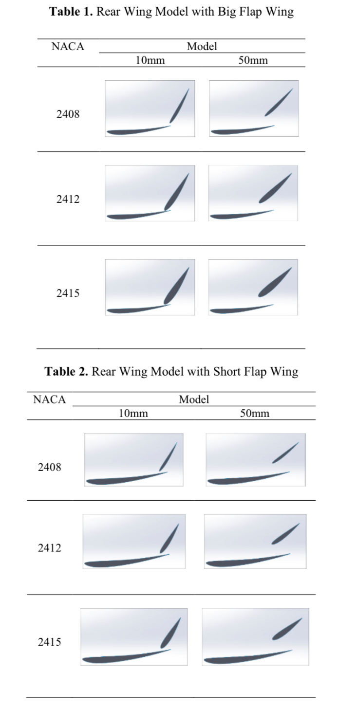
Figure 1. Rear Wing Model with big flap wing.

Figure 2. Rear Wing Model with short flap wing.
3. The design of the rear wing of different sports cars
3.1. Design motivation
Modern cars use different amounts of fuel energy when driving in the city and when driving on the highway. Driving a car in the city requires about 3% of the fuel used to overcome relative drag, while driving a car on the highway requires 11%. Because of the high fuel consumption when driving on the highway, this has attracted some design engineers to use minimal design changes to improve the aerodynamic performance of the vehicle, Of course, they also take into account a variety of factors that can generate friction. For instance, shear forces on a vehicle's surface can result in skin friction resistance, which is brought on by the rubbing of a moving object's skin against a fluid [5]. The concept of tail fins emerged as a solution to reduce drag and enhance fuel efficiency without altering the body of the car. In modern vehicle designs, many models feature a relatively large angle at the rear, extending from the roof to the trunk or rear of the car. At higher speeds, the air flowing over this edge tends to become turbulent, leading to flow separation [6]. This turbulence creates a low-pressure area at the rear of the car, resulting in increased drag (Figure 3). To address this issue, a trailing edge can be added to the very rear of the vehicle. This extension provides the air with a longer and smoother slope from the roof to the trailing edge, effectively minimizing flow separation (Figure 4). By reducing flow separation, drag is decreased, leading to improved fuel economy. Additionally, the smooth airflow through the rear window helps maintain clear visibility in the rear of the vehicle.
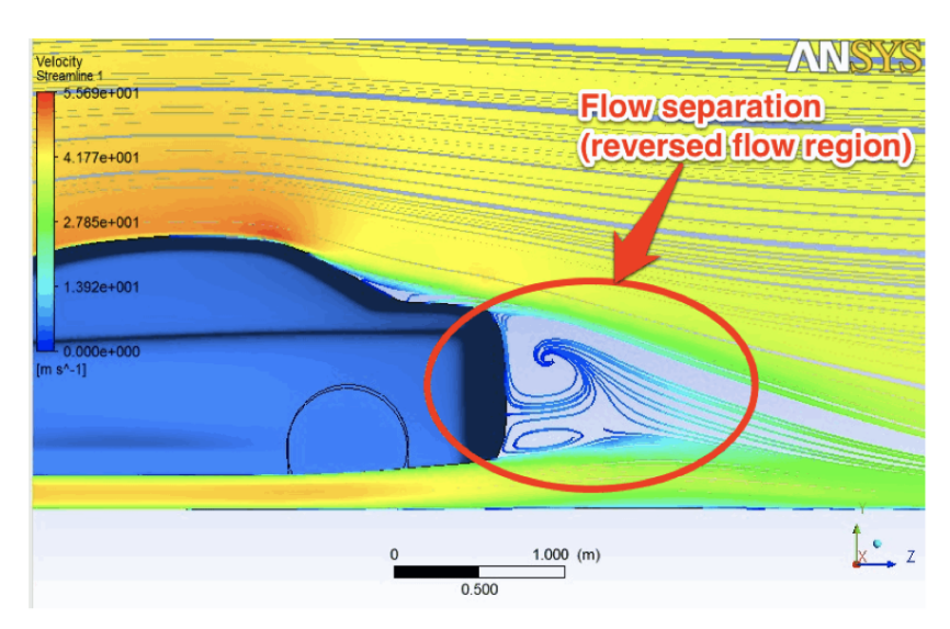
Figure 3. Low pressure area is created at the rear of the car.
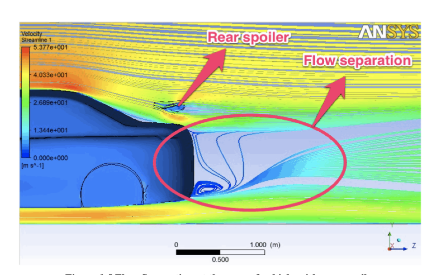
Figure 4. Smoother slope to reduce flow separation.
3.2. Design method
Recent advancements in computer hardware and the limitations of traditional wind tunnel experiments have led to significant efforts in the field of vehicle aerodynamics over the past decade [7]. This progress has enabled more rigorous calculations and studies in this domain. In this research paper, the authors present a numerical simulation of the airflow around a racing car, examining the impact of a tail fin using the ANSYS FLUENT commercial fluid dynamics software. The primary focus of this study is to employ computational fluid dynamics (CFD) for predicting the lift and drag characteristics of the vehicle [8]. To conduct the simulation, a 3D computer model of a four-door sedan, created with the SolidWorks software, serves as the baseline model. The subsequent step involves incorporating the tail fin at various locations on the rear end of the vehicle to investigate its aerodynamic effects. The authors aim to analyze the impact of the tail fin on the vehicle's performance. In terms of the experimental design, two different styles of tail fins were employed. The first style (Figure 6) featured a "wing" configuration, mounted 23 cm above the rear surface of the vehicle. The second tail fin was positioned at the rear edge of the vehicle, with no gap between the tail fin and the vehicle surface. These variations were implemented to assess the influence of different tail fin placements on the aerodynamics of the vehicle.
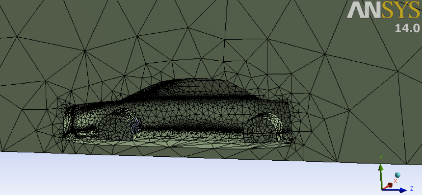
Figure 5. Mesh generation with standard settings.
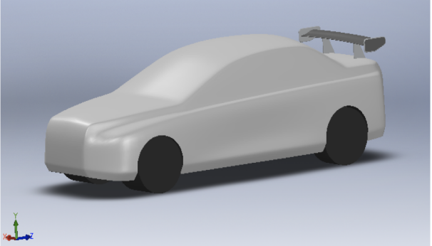
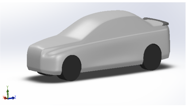
Figure 6. Different tail fins.
To simulate the aerodynamic behavior, the authors employed ANSYS FLUENT®, utilizing a three-dimensional steady-state approach with incompressible Navier-Stokes equations. Turbulence was modeled using a k-ε model with nonequilibrium wall functions. Three different modeling cases were considered: Case #1 represented the vehicle model without a wake, Case #2 incorporated the first wake design, and Case #3 featured the second wake design. It is worth noting that all cases utilized the same mesh resolution (Figure 5), k-ε turbulence model, and boundary conditions. The free-stream velocity was set at 30 m/s (approximately 65 mph), equivalent to the typical speed limit on highways. Following the tests, it was observed that Case #3 did not exhibit as significant an effect as Case #2. The drag coefficient only decreased to 0.217 in Case #3. However, there was a notable alteration in both drag and downforce (negative lift) on the car body (Figure 7). Comparing Case #2 and Case #3, which had identical grid resolution, turbulence model, and boundary conditions, the authors concluded that the reduction in drag resulting from the presence of a wake at the rear of the vehicle was predominantly influenced by the specific shape of the wake.
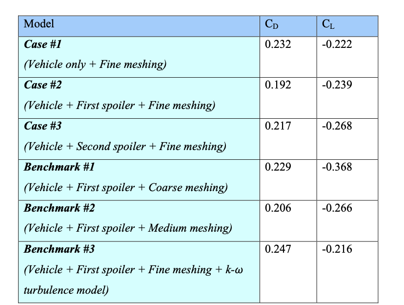
Figure 7. Drag and downforce influence on the car body.
3.3. Analysis and discussion
In contemporary leading automotive companies such as Porsche and Bugatti, the traditional rear wing has undergone significant upgrades through electromechanical advancements, aiming to optimize its efficiency by minimizing adverse effects at low speeds and enhancing benefits at high speeds. A notable example is the Bugatti Veyron, where a hydraulic rear wing system [9] is employed. At elevated speeds, the rear wing rises to generate downward pressure, ensuring the safety of both the vehicle and the driver. Additionally, when the car reaches speeds of 220 km/h, the hydraulic mechanism extends the rear wing over a foot, providing a substantial 330 pounds of downward pressure [10]. This effectively secures the vehicle's stability on the road surface.
It is crucial to consider that while a rear wing generates downward force to enhance performance, it also induces aerodynamic drag. Hence, the "lift/drop ratio" assumes significant importance in car design. Designers have been striving to maximize this ratio, ensuring that the vehicle possesses sufficient power to maneuver corners while maintaining an optimal speed. For instance, Formula 1 (F1) cars can achieve approximately 3G of downforce at speeds of 200 mph, allowing them to maintain exceptional traction and adhere closely to the track. However, the advantages of generating downward force, or negative lift, extend beyond cornering capabilities. Negative lift enhances tire grip during cornering, stabilizes the vehicle at high speeds, improves braking performance, and augments traction. In passenger cars, prioritizing higher levels of negative lift takes precedence over reducing drag, as safety remains the paramount concern. It is noteworthy that the benefits of a rear wing predominantly manifest at higher speeds, whereas at most lower speeds, the rear wing may potentially impede the vehicle's performance. Consequently, the automotive industry has dedicated significant efforts to address these adverse effects, with various car manufacturers devising solutions to mitigate the negative repercussions associated with tail fins.
4. Conclusion
In conclusion, the aerodynamics-based design of the rear wing of a sports car is a complex and highly specialized field that requires a deep understanding of fluid mechanics, computational simulations, and testing procedures. The rear wing of a sports car plays a crucial role in improving the car's performance by providing downforce and reducing drag. The design process involves a detailed analysis of the car's body, air flow, and wing geometry. The use of advanced computational tools such as Computational Fluid Dynamics (CFD) simulations allows designers to optimize the wing's shape, size, and angle of attack for the specific car and driving conditions. Ultimately, the success of the rear wing design depends on how well it integrates with the rest of the car's aerodynamic components and the driver's skill. With careful consideration of these factors, designers can create a rear wing that enhances the car's performance, providing better handling, stability, and speed. The aerodynamics-based design of the rear wing of a sports car is an exciting field that continues to evolve as new technologies and materials are developed, and it plays a significant role in pushing the limits of automotive engineering.
References
[1]. Rouméas, M., Gilliéron, P., & Kourta, A. (2008). Drag Reduction by Flow Separation Control on a Car After Body. International Journal of Numerical Methods in Fluids, 60. ISSN 0271-2091.
[2]. Tu, J., Yeoh, G. H., & Liu, C. (2007). Computational Fluid Dynamics: A Practical Approach (1st ed.). Butterworth-Heinemann.
[3]. Seibert, W. (2001). CFD in Aerodynamic Design Process of Road and Race Cars. Fluent Deutschland GmbH, FLUENT Technical Notes TN155, Presented at European Automotive Congress, Bratislava, Slovakia.
[4]. Bugatti Page. (n.d.). Retrieved March 31, 2023, from http://bugattipage.com/ride.htm
[5]. Kourta, A., & Gilliéron, P. (2009). Impact of the Automotive Aerodynamic Control on the Economic Issues. Journal of Applied Fluid Mechanics, 2(2), 69-75. ISSN 1735-3645.
[6]. Azmi, A. R. S., Sapit, A., Mohammed, A. N., Razali, M. A., Sadikin, A., & Nordin, N. (n.d.). Study on Air Flow Characteristics of Real Wing of F1. Published under licence by IOP publishing Ltd.
[7]. Basso, M., Cravero, C., & Marsano, D. (n.d.). Aerodynamic Effect of the Gurney Flap on the Front Wing of a F1 Car and Flow Interactions with Car Components.
[8]. Chen, K., & Liu, S. (n.d.). Analysis and Optimization of Aerodynamic Performance of Race Car Rear Wing Based on CFD.
[9]. Katz, J. (n.d.). Aerodynamics of Race Cars. Department of Aerospace Engineering, San Diego State University. Email: jkatz@mail.sdsu.edu.
[10]. Gersten, K., Krause, E., Oertel Jr., H., & Mayes, C. (2004). Boundary-Layer Theory (8th ed.). Springer.
Cite this article
Qiu,Z.;Zhang,H. (2023). Aerodynamics-based design of the rear wing of a sports car. Applied and Computational Engineering,11,310-317.
Data availability
The datasets used and/or analyzed during the current study will be available from the authors upon reasonable request.
Disclaimer/Publisher's Note
The statements, opinions and data contained in all publications are solely those of the individual author(s) and contributor(s) and not of EWA Publishing and/or the editor(s). EWA Publishing and/or the editor(s) disclaim responsibility for any injury to people or property resulting from any ideas, methods, instructions or products referred to in the content.
About volume
Volume title: Proceedings of the 2023 International Conference on Mechatronics and Smart Systems
© 2024 by the author(s). Licensee EWA Publishing, Oxford, UK. This article is an open access article distributed under the terms and
conditions of the Creative Commons Attribution (CC BY) license. Authors who
publish this series agree to the following terms:
1. Authors retain copyright and grant the series right of first publication with the work simultaneously licensed under a Creative Commons
Attribution License that allows others to share the work with an acknowledgment of the work's authorship and initial publication in this
series.
2. Authors are able to enter into separate, additional contractual arrangements for the non-exclusive distribution of the series's published
version of the work (e.g., post it to an institutional repository or publish it in a book), with an acknowledgment of its initial
publication in this series.
3. Authors are permitted and encouraged to post their work online (e.g., in institutional repositories or on their website) prior to and
during the submission process, as it can lead to productive exchanges, as well as earlier and greater citation of published work (See
Open access policy for details).
References
[1]. Rouméas, M., Gilliéron, P., & Kourta, A. (2008). Drag Reduction by Flow Separation Control on a Car After Body. International Journal of Numerical Methods in Fluids, 60. ISSN 0271-2091.
[2]. Tu, J., Yeoh, G. H., & Liu, C. (2007). Computational Fluid Dynamics: A Practical Approach (1st ed.). Butterworth-Heinemann.
[3]. Seibert, W. (2001). CFD in Aerodynamic Design Process of Road and Race Cars. Fluent Deutschland GmbH, FLUENT Technical Notes TN155, Presented at European Automotive Congress, Bratislava, Slovakia.
[4]. Bugatti Page. (n.d.). Retrieved March 31, 2023, from http://bugattipage.com/ride.htm
[5]. Kourta, A., & Gilliéron, P. (2009). Impact of the Automotive Aerodynamic Control on the Economic Issues. Journal of Applied Fluid Mechanics, 2(2), 69-75. ISSN 1735-3645.
[6]. Azmi, A. R. S., Sapit, A., Mohammed, A. N., Razali, M. A., Sadikin, A., & Nordin, N. (n.d.). Study on Air Flow Characteristics of Real Wing of F1. Published under licence by IOP publishing Ltd.
[7]. Basso, M., Cravero, C., & Marsano, D. (n.d.). Aerodynamic Effect of the Gurney Flap on the Front Wing of a F1 Car and Flow Interactions with Car Components.
[8]. Chen, K., & Liu, S. (n.d.). Analysis and Optimization of Aerodynamic Performance of Race Car Rear Wing Based on CFD.
[9]. Katz, J. (n.d.). Aerodynamics of Race Cars. Department of Aerospace Engineering, San Diego State University. Email: jkatz@mail.sdsu.edu.
[10]. Gersten, K., Krause, E., Oertel Jr., H., & Mayes, C. (2004). Boundary-Layer Theory (8th ed.). Springer.