


1. Introduction
Steel truss girder bridges have been used in Nanjing Dashengguan Yangtze River Bridge, Qiantang River Bridge and other mega bridge projects because of their simple construction, high load carrying capacity, high longitudinal and transverse stiffness and short construction period [1]. At present, bridge structures are mainly analyzed for structural safety by comparing the cross-sectional internal forces and resistances of the members based on the consideration of various influence coefficients, which is a safety analysis method at the member level [2]. Although this method is simple and practical, it cannot grasp the contribution of each component to the overall safety of the structure from the bearing state and failure mode. It is difficult to optimize the bearing capacity distribution and material consumption of the structure [3]. For this reason, it is necessary to carry out the overall safety analysis and structural optimization at the structural level [4].
The finite element method is the first choice for structural analysis of truss bridges. The finite element method, since the basic idea and method proposed by Martin, Tuner, Clough, etc. in the middle of the 20th century. And, it has developed into a rigorous theoretical foundation and a wide range of application analysis methods [5-8]. This paper combines the advantages and disadvantages of each of the two finite element software, ABAQUS and MIDAS, for finite element modelling. The elastic modulus reduction method (EMRM) proposed in recent years gives a new elastic modulus adjustment strategy based on the conservation principle of element bearing ratio and strain energy. The influence of all internal force combination effects of the section on member failure can be considered by introducing a generalized yield criterion. By reducing the elastic modulus of high load-bearing members and iteratively calculating the linear elastic finite element method, a series of static allowable internal force fields are formed in the structure. The gradual failure process of components and structures is simulated, and the ultimate bearing capacity of structures is solved based on it [9].
2. Finite element modeling
The finite element analysis method plays an important role in modern bridge design. The use of finite element software to analyse the performance of steel truss bridge is not only more convenient and intuitive, but also more accurate, which needs to be fully used to improve the level of structural design. The modelling work is the most important part of the whole finite element analysis, and it is necessary to choose the appropriate software to complete the modelling. However, different finite element analysis software has been adopted for modelling and analysis of bridges, which have their own advantages and disadvantages.
1. Selection of finite element software
Based on the use and summary of each finite element software, this paper adopts ABAQUS and MIDAS software for finite element modelling and analyses the characteristics of the software to complement the advantages and disadvantages of the two software.
MIDAS is more accurate for the whole structure calculation and rough for the node calculation, so it is more suitable for the whole steel truss bridge modelling analysis. Different from MIDAS, ABAQUS model and calculation are more accurate and more suitable for modelling and analysis of detailed structures. However, the boundary conditions are required to be correct and comprehensive. In actual engineering, it is difficult to extract the forces and moments at the detail structure to meet the pre-processing data requirements of ABAQUS calculation [10].
2. MIDAS finite element modelling
MIDAS software is a data processing software based on structural design finite element analysis, which has a broad application prospect in the bridge field. A steel truss bridge (Nanjing Dashengguan Yangtze River Bridge) with a length of 1270m, a width of 34m and a height of 26.6m was constructed by using MIDAS software with reference to an example steel truss bridge. The material of the bridge was set as Q420 steel under GB03S standard, and the bridge was set to be constructed by six main members. After the material and cross-section were defined, the relevant nodes were established first, and then the nodes were connected sequentially with the set units to improve the connection between the truss structures and finally form a complete bridge model (Figure 1).
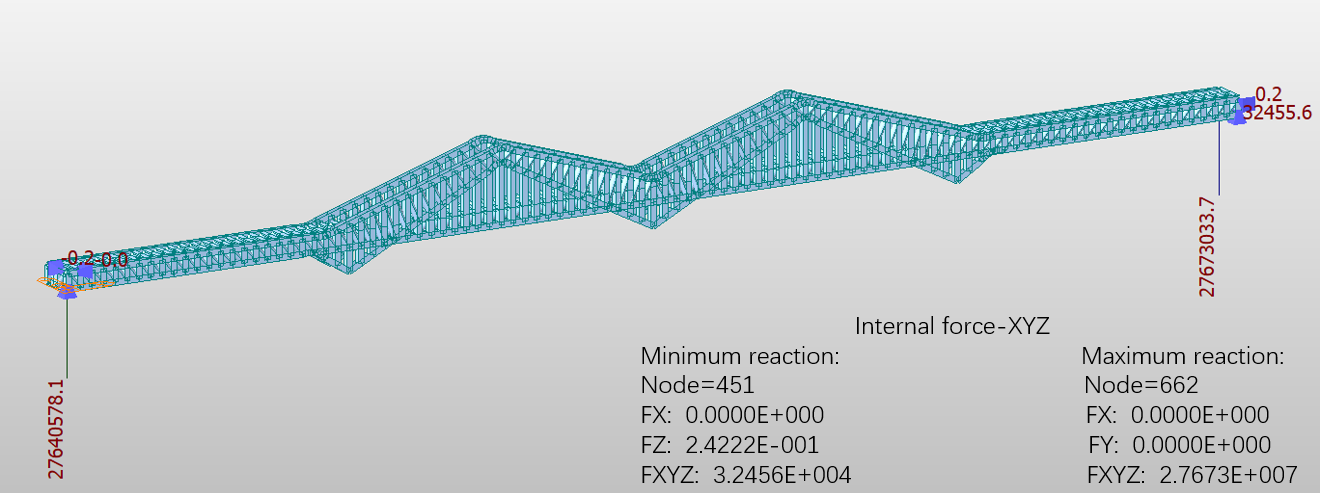
Figure 1. Bridge modeling model and its related parameters.
The relevant static analysis was performed, and a uniform load of 21kN/m was applied to the full bridge for the load condition, and the calculations were run and entered the post-processing stage, where the displacement and stress diagrams were obtained, with the following results (Figure 2 and 3):
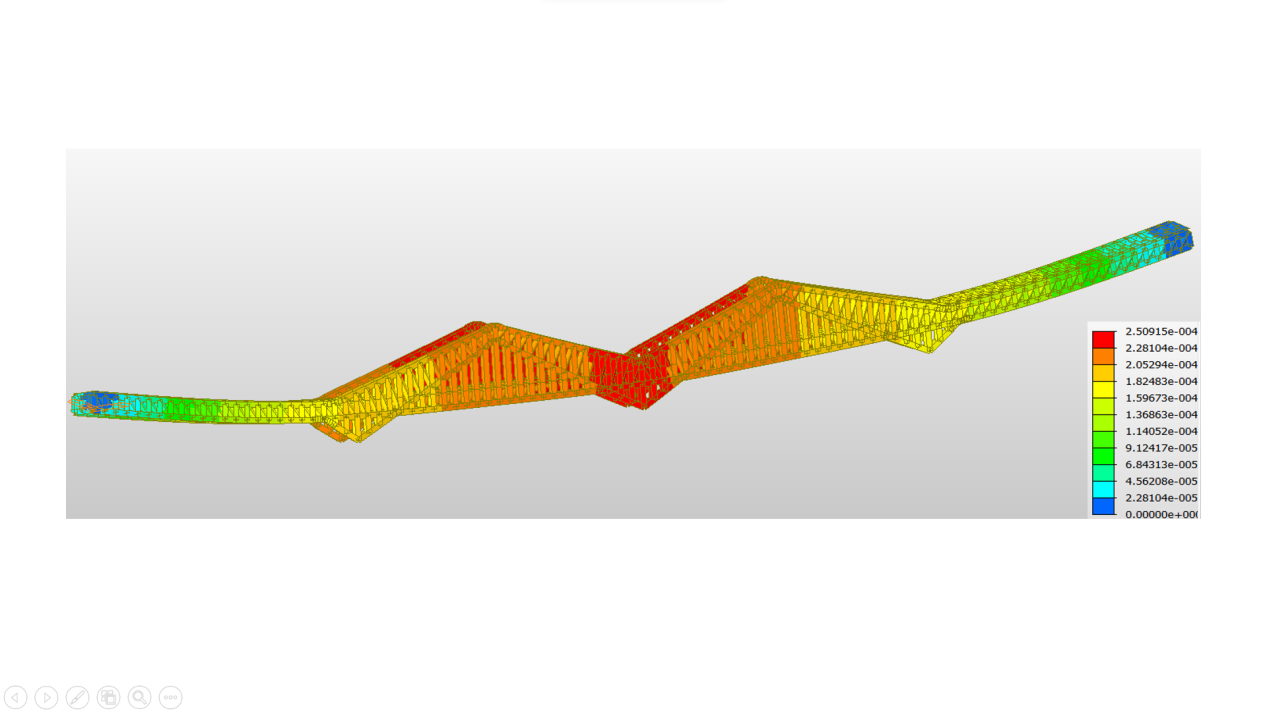
Figure 2. Model Stress Diagram.
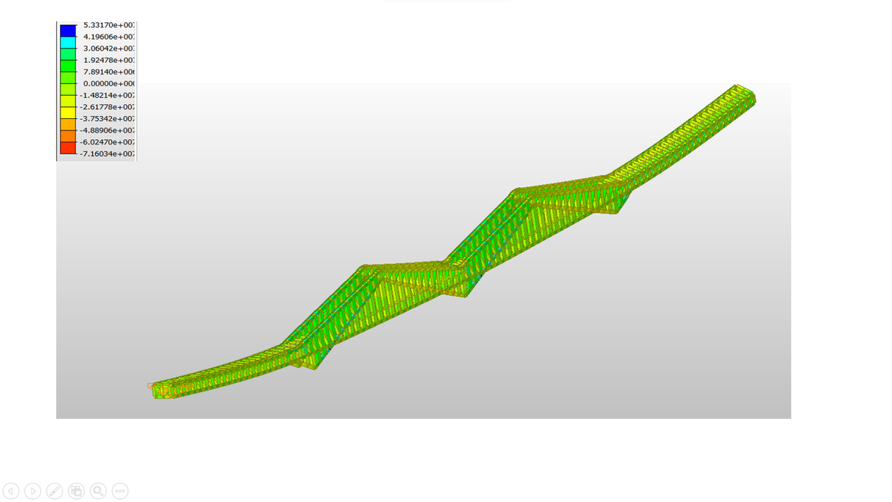
Figure 3. Model displacement diagram.
It can be seen that the internal force of the joist is mainly axial force, the upper chord is under compression and the lower chord is under tension, the mid-span position is the maximum stress, and the stress decreases to both sides, the vertical deflection of the mid-span node is the largest.
Since there is moment transfer between the rods of this steel truss bridge, the MIDAS model using beam unit is more in line with the engineering reality and can simplify the calculation. The following load types are added: bridge self-weight, overall warming, overall cooling, dynamic load, The internal forces of the beam unit after different working conditions are extracted and recorded by MIDAS, and the extracted data are loaded as part of the boundary conditions for ABAQUS calculation.
3. ABAQUS finite element modelling
In steel truss bridge, the load is transferred to the main truss node through each rod, and then to the bearing and foundation. Therefore, the nodes play a pivotal role in the process of force transmission. ABAQUS is used to number the nodes of the steel truss and to build 2D and 3D models of the steel truss structure in order to optimize the analysis of the truss in detail and accurately.
In this paper, the N-shaped steel truss of 108m side span bridge of Nanjing Dashengguan Yangtze River Bridge is used as the research object for modelling, as shown in Figure 4. ABAQUS has a rich library of material models, which can simulate most common engineering materials. The material of the main truss is Q420qE steel. The material has a yield strength of 420MPa , a density of 7.85×10³kg/m3, a modulus of elasticity of E=2.1×10¹⁰N/m2 and a Poisson's ratio of 0.3. The main truss is 16m high with 12m long sections. The bridge main truss consists of upper chord, lower chord and web (diagonal and vertical bars). The upper and lower chords are connected to the webs through integral nodes. The cross-sectional area of upper and lower chords is set to 1.2×10⁻²m2 and the cross-sectional area of webs is set to 1.4×10⁻²m2.

Figure 4. Steel truss modeling model.
After completing the modeling, the static analysis is performed first. The restraint is applied at the two end supports; the load condition is 21kN/m for the whole bridge. From Figure 5, it can be seen that the internal force of the truss is mainly axial force, the upper chord is under compression and the lower chord is under tension, the maximum stress is at the upper side of the span and the stress decreases to both sides, the vertical deflection of the nodes in the middle of the span is the largest. These are consistent with the theoretical analysis and MIDAS analysis results.
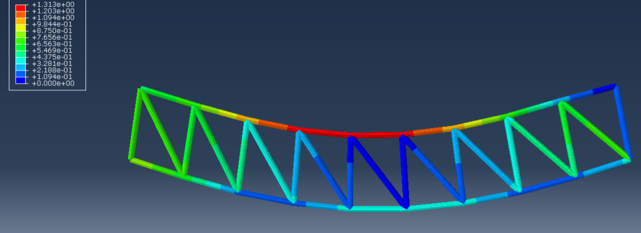
Figure 5. Stress diagram of steel truss.
3. Elastic modulus reduction method
1. Stability limit bearing capacity solution method
The elastic modulus reduction method can strategically reduce the elastic modulus of high-bearing elements in steel truss Bridges. The stiffness damage of steel truss bridge during loading can be simulated by elastic modulus reduction method, and the stable ultimate bearing capacity of steel truss bridge can be calculated by linear elastic iterative analysis. For a steel truss bridge structure subjected to n loads P1, P2,...Pn, the external load can be represented by the vector P as:
P=P0αi=P0[α1,α2,⋯,αn]T#(1)
where P0 and αi are the load reference value and load multiplier, respectively.
The unit load bearing ratiorek, as an important parameter of the modulus of elasticity reduction method, characterizes the extent to which the section enters full section yielding. rek=1 indicates that the full section yields, whilerek=0 indicates that the section is unstressed. rek can be defined by using¯f4, f is the generalized yield function.
rek=4√¯f4(nx,my)=√f#(2)
where k is the iteration step; e is the cell number.
Accordingly, the base load ratior0k for identifying the dynamic threshold of the high load cell can be defined as:
r0k=rk(rkminkmax)kmax#(3)
dk=¯rk+rkmin
where r_{k\max} is the maximum cell load ratio in the structure; r_{k\min} is the minimum cell load ratio in the structure;d_{k} is the uniformity of load ratio;N_{M} is the total number of meshed cells.
Where the unit bearing ratio is greater than the base bearing ratior_{K}^{0} is the high bearing unit of thek iteration step. The elastic modulus reduction method combined with the principle of conservation of unit deformation energy establishes the elastic modulus adjustment strategy [11-12].
{E_{k + 1}^{e} = \left\{ \begin{aligned} & E_{k}^{e}\frac{2\left( r_{k}^{0} \right)^{2}}{\left( r_{k}^{e} \right)^{2} + \left( r_{k}^{0} \right)^{2}} \\ & E_{k}^{e} \end{aligned} \right.\ ,\ r}_{k}^{e} > r_{k}^{0}
\begin{array}{r} r_{k}^{e} \leq r_{k}^{0}\#\text{(}\text{5}\text{)} \end{array}
where E_{k}^{e} andE_{k + 1}^{e} are the values of the elastic modulus of the cell e during the k and k+1 iterations, respectively. When k+1 is used,E_{k}^{e} takes the combined modulus of elasticity valueE_{sc} .
Based on the results of the linear elastic finite element analysis, the unit load carrying ratior_{k}^{e} is obtained. Since the unit load carrying ratio is proportional to the external load, the ultimate load carrying capacity of the structure at the iteration stepk can be obtained from the maximum unit load carrying ratio r_{k\max}.
\begin{array}{r} P_{k}^{L} = \frac{P_{0}}{r_{kmax}}\#\text{(}\text{6}\text{)} \end{array}
The above calculation process should be repeat to ensure that the ultimate bearing capacity of the two adjacent steps meets the following convergence criteria.
\begin{array}{r} \left| \frac{P_{k}^{L} - P_{k - 1}^{L}}{P_{k - 1}^{L}} \right| \leq \varepsilon k \geq 2\#\text{(}\text{7}\text{)} \end{array}
where \varepsilon is the convergence tolerance. As a criterion of convergence, it usually takes the value of 0.001~0.01, and in this paper, it takes 0.001.
If the M iteration satisfies the convergence criterion of equation (7), then the ultimate bearing capacity PL of the structure is:
\begin{array}{r} P_{L} = P_{M}^{L} = \frac{P_{0}}{r_{M}^{\max}}\#\text{(}\text{8}\text{)} \end{array}
From modelling to iterative steps, the whole calculation process of elastic modulus reduction method belongs to linear elastic iterative analysis, which does not involve nonlinear behaviour of materials. The stability and high efficiency of the iterative calculation process are ensured [13].
2. Safety analysis method for truss members
According to the first iteration of the Elastic Modulus Reduction Method (EMRM), equation (2) is used to obtain the unit bearing ratio of each member of the steel truss bridge under the design loadr_{1}^{e} , and then the member safety factor is obtained as follows:
\begin{array}{r} K_{S}^{e} = \frac{1}{r_{1}^{e}}\#\text{(}\text{9}\text{)} \end{array}
where K_{S}^{e} represents the safety factor of the member unit e , which reflects the safety reserve condition of the member under the combined effect of internal forces.
The structural load carrying capacity safety assessment of the bridge is performed at the member level according toK_{S}^{e}. When\min\left( K_{S}^{e} \right) > 1 is used, it means that none of the members has failed. On the contrary, when a member isK_{S}^{e} \leq 1 , the member will enter the load carrying capacity limit state. Usually the design of the structure requires a certain safety margin, not allowingK_{S}^{e} to be too close to 1 [14].
3. Safety analysis method of truss structure
According to the results of the last step of EMRM elastic iterative analysis, the ultimate load of the structure is obtained from PL, and then combined with equation (8), the overall safety factor of the truss structure is obtained.
\begin{array}{r} K_{T} = \frac{P_{L}^{0}}{P} = \frac{1}{r_{M}^{\max}}\#\text{(}\text{10}\text{)} \end{array}
where KT is the overall structural safety factor or structural safety factor, which can reflect the overall load bearing state and safety reserve condition of the bridge structure.
The overall safety of the bridge can be assessed at the structural level according to KT . When KT>1 , it indicates that the structure will not develop an overall failure mode under the current load bearing condition. On the contrary, when KT≤1 indicates that the structure enters the load carrying capacity limit state and will fail. Therefore, it is required that the structural safety factor should not be too close to 1, so as to guarantee a certain margin of safety for the structure as a whole.
From equation (9), it can be seen that the overall structural safety factor KT can be obtained based on the member with the largest unit load bearing ratior_{M}^{\max} in the last iteration of EMRM, according to which the overall structural safety can be judged. It can be seen that the structural load capacity is closely related to the member load capacity, and according to the correlation between the two, the structural design can be optimized based on safety considerations.
4. Model solving analysis
According to the results of the first iteration of EMRM, the bearing ratio of each unit and the corresponding safety factor can be obtained, and the geometric parameters of the bar sections are listed in Table 1, and the steel truss model rod numbers are shown as Figure 6. Group 2 is all the lower chords except those near the supports and Group 3 is the lower chords near the supports at both ends of the bridge. As shown in Table 2, the results of the first iteration show that the safety factor of all members of the steel truss bridge under this condition is greater than 2, which indicates that the structural design meets the load carrying safety and no structural failure will occur under normal conditions.
Table 1. Geometric parameters of rod section.
Rod category | Rod number | Cross-sectional area /m2 | Cross-sectional moment of inertia/m4 |
|---|---|---|---|
Wind-up bar | 3,30~37 | 1.2×10⁻² | 1.44×10⁻⁵ |
Downswing bar | 1,5~12 | 1.2×10⁻² | 1.44×10⁻⁵ |
Ventral rod | 2,4,13~29 | 1.4×10⁻² | 2.04×10⁻⁵ |
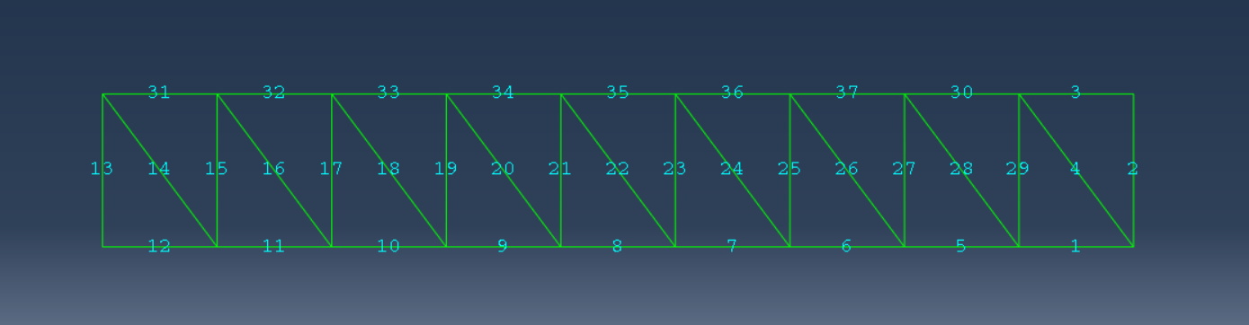
Figure 6. Steel truss model rod numbering.
Table 2. Component safety factor.
Group number | Build Unit Number | Component safety factor |
|---|---|---|
1 | 3, 30 to 37 | 2.63 |
2 | 5 to 11 | 4.21 |
3 | 1,12 | 7.53 |
Multiple iterations are carried out for the member unit bearing ratio. As shown in Figure 7, the horizontal coordinate is the number of iterations and the vertical coordinate is the unit bearing ratio. According to the last iteration result, the ultimate bearing capacity PL=61.73kN/m of the steel truss beam bridge can be obtained, so the overall structural safety factor of the steel truss girder bridge is:
\begin{array}{r} K_{T} = \frac{1}{r_{M}^{\max}\frac{P_{L}^{0}}{P}\frac{61.73}{21.00}}\#\text{(}\text{11}\text{)} \end{array}
The combination of the member safety factor and the overall structural safety factor shows that the bridge can maintain a certain safety reserve at both the member and structural levels without local failure or overall failure.
Figure 7. Iterative process of component unit load ratio.
5. Conclusion
In this paper, a steel truss bridge is constructed, and the bridge model is established by dividing the discrete elements into truss beams, and the discrete elements are determined. MIDAS takes the whole of the relevant bridge as the modeling reference object, while ABAQUS takes the relevant side span bridge truss as the modeling object. After the modeling is completed, comparing the data obtained by the two-software analysis, it is found that the internal force of the truss, the compression and tension situation of the upper and lower chord and the maximum stress concentration position are the same, and are consistent with the theoretical analysis. In structural analysis, EMRM and elastic modulus analysis were adopted to determine the element bearing ratio and reference bearing ratio, and then the elastic modulus of the element was reduced, and the ultimate load of the structure was determined by calculating the specific iteration steps, that is, the rare load that the structural system could bear.
In this paper, the elastic modulus reduction method is used to solve the component safety factor and the whole safety factor of the bridge structure, and then the safety of the steel truss beam bridge is analyzed from the two aspects of the component and structure. The generalized yield criterion and elastic modulus reduction method are introduced into the safety analysis of steel truss girder Bridges. The influence of combined internal forces on structural safety is considered, and the problem that the structural safety may be biased when the structural safety is evaluated according to a single internal force is overcome. The EMRM structure optimization method adopted in the optimization design section overcomes the defects of the traditional structure optimization design method. According to the variation of the unit load ratio in the iterative calculation process, the high-load and low-load components of the bridge structure can be identified. Finally, the structure is optimized by adjusting the sectional strength of the high-load and low-load members. The optimization by using EMRM method not only makes up for the defects neglected by traditional methods, which do not consider the influence of internal force redistribution when the structure enters the elastic-plastic state or even the plastic limit state under rare loads (that is, the ultimate load), so it cannot meet the strength requirements of the structural system. It can also improve the utilization rate of materials, thereby reducing the consumption of materials and maximizing the benefit of resources.
Since simplified measures were adopted in the modeling process of this study, and many factors were not involved, the next step is to consider and analyze the effects of wind loads, automobile loads and crowd loads on the structural strength and stiffness of steel truss bridges. In addition, natural disasters have a great impact on the destruction of buildings, especially earthquakes, which can cause damage and even collapse of bridges, threatening the life safety of citizens and causing huge losses to the national economy. Therefore, seismic analysis and seismic response analysis of bridges are particularly important. It is found through investigation that the seismic resistance of the whole bridge structure can be further studied through inverse spectrum analysis.
All the authors contributed equally and their names were listed in alphabetical order.
JTGD60 2004 General Specification for the Design of Highway Bridges and Culverts (Beijing: China Construction Industry Press)
JTG/TJ21 2011 Highway Bridge Load Capacity Testing and Assessment Procedure (Beijing: People's Traffic Publishing House)
JTG/TH21 2011 Technical condition assessment standard for highway bridges (Beijing: People's Traffic Publishing House)
Li Y 1996 Code-based assessment for load-carrying capacity of bridges Bridge Constr. 26(2) 61-63
Zienkiewicz O C and R.L.Taylor 2005 The Finite Element Method,5thed (Beijing: World Book Publishing Company)
Kuichiro Wasutsu 1984 The Variational Method in Elasticity and Plasticity (Beijing: Science Press)
Feng K and Shi Z C 1981Mathematical Theory of Elastic Structure (Beijing: Science Press)
Qian W C 1980 Variational Method and Finite Element (Beijing: Science Press)
Yang L F, Yu B and Qiao Y P 2009 Limit bearing capacity analysis of frame using elastic modulus reduction method Acta Mechanica Solida 22(2) 109-115
Zhang Q, Gao J Q and Liu P 2020 Finite element analysis of steel nodes of steel truss bridges Highway 65(07) 135-140
Yang L F, Yu B and Ju J W 2015 Incorporated Strength Capacity Technique for Limit Load Evaluation of Trusses and Framed Structures under Constant Loading J. Struct. Eng. 141(11) 4015023
Yang L F, Li Q and Zhang W et al. 2014 Homogeneous Generalized Yield Criterion Based Elastic Modulus Reduction Method for Limit Analysis of Thin-Walled Structures with Angle Steel Thin-Walled Struct. 80 (9) 153-158
Xie W W, Ye Z Q and Yang L F. 2018 Iterative linear elastic method for stable ultimate bearing capacity of steel-tube concrete arch bridge China Railway Sci. 39(01) 39-48
Yang L F, Li Q and Zhang W 2013 Analysis and optimization of two-level load bearing capacity of steel truss girder bridge structure Civil Constr. Envir. Eng. 35(06) 51-57
References
[1]. JTGD60 2004 General Specification for the Design of Highway Bridges and Culverts (Beijing: China Construction Industry Press)
[2]. JTG/TJ21 2011 Highway Bridge Load Capacity Testing and Assessment Procedure (Beijing: People's Traffic Publishing House)
[3]. JTG/TH21 2011 Technical condition assessment standard for highway bridges (Beijing: People's Traffic Publishing House)
[4]. Li Y 1996 Code-based assessment for load-carrying capacity of bridges Bridge Constr. 26(2) 61-63
[5]. Zienkiewicz O C and R.L.Taylor 2005 The Finite Element Method,5thed (Beijing: World Book Publishing Company)
[6]. Kuichiro Wasutsu 1984 The Variational Method in Elasticity and Plasticity (Beijing: Science Press)
[7]. Feng K and Shi Z C 1981Mathematical Theory of Elastic Structure (Beijing: Science Press)
[8]. Qian W C 1980 Variational Method and Finite Element (Beijing: Science Press)
[9]. Yang L F, Yu B and Qiao Y P 2009 Limit bearing capacity analysis of frame using elastic modulus reduction method Acta Mechanica Solida 22(2) 109-115
[10]. Zhang Q, Gao J Q and Liu P 2020 Finite element analysis of steel nodes of steel truss bridges Highway 65(07) 135-140
[11]. Yang L F, Yu B and Ju J W 2015 Incorporated Strength Capacity Technique for Limit Load Evaluation of Trusses and Framed Structures under Constant Loading J. Struct. Eng. 141(11) 4015023
[12]. Yang L F, Li Q and Zhang W et al. 2014 Homogeneous Generalized Yield Criterion Based Elastic Modulus Reduction Method for Limit Analysis of Thin-Walled Structures with Angle Steel Thin-Walled Struct. 80 (9) 153-158
[13]. Xie W W, Ye Z Q and Yang L F. 2018 Iterative linear elastic method for stable ultimate bearing capacity of steel-tube concrete arch bridge China Railway Sci. 39(01) 39-48
[14]. Yang L F, Li Q and Zhang W 2013 Analysis and optimization of two-level load bearing capacity of steel truss girder bridge structure Civil Constr. Envir. Eng. 35(06) 51-57
Cite this article
Yang,X.;Li,X.;Sun,P. (2023). Structural analysis and optimization of steel truss bridge based on finite element method. Applied and Computational Engineering,25,133-141.
Data availability
The datasets used and/or analyzed during the current study will be available from the authors upon reasonable request.
Disclaimer/Publisher's Note
The statements, opinions and data contained in all publications are solely those of the individual author(s) and contributor(s) and not of EWA Publishing and/or the editor(s). EWA Publishing and/or the editor(s) disclaim responsibility for any injury to people or property resulting from any ideas, methods, instructions or products referred to in the content.
About volume
Volume title: Proceedings of the 2023 International Conference on Functional Materials and Civil Engineering
© 2024 by the author(s). Licensee EWA Publishing, Oxford, UK. This article is an open access article distributed under the terms and
conditions of the Creative Commons Attribution (CC BY) license. Authors who
publish this series agree to the following terms:
1. Authors retain copyright and grant the series right of first publication with the work simultaneously licensed under a Creative Commons
Attribution License that allows others to share the work with an acknowledgment of the work's authorship and initial publication in this
series.
2. Authors are able to enter into separate, additional contractual arrangements for the non-exclusive distribution of the series's published
version of the work (e.g., post it to an institutional repository or publish it in a book), with an acknowledgment of its initial
publication in this series.
3. Authors are permitted and encouraged to post their work online (e.g., in institutional repositories or on their website) prior to and
during the submission process, as it can lead to productive exchanges, as well as earlier and greater citation of published work (See
Open access policy for details).
References
[1]. JTGD60 2004 General Specification for the Design of Highway Bridges and Culverts (Beijing: China Construction Industry Press)
[2]. JTG/TJ21 2011 Highway Bridge Load Capacity Testing and Assessment Procedure (Beijing: People's Traffic Publishing House)
[3]. JTG/TH21 2011 Technical condition assessment standard for highway bridges (Beijing: People's Traffic Publishing House)
[4]. Li Y 1996 Code-based assessment for load-carrying capacity of bridges Bridge Constr. 26(2) 61-63
[5]. Zienkiewicz O C and R.L.Taylor 2005 The Finite Element Method,5thed (Beijing: World Book Publishing Company)
[6]. Kuichiro Wasutsu 1984 The Variational Method in Elasticity and Plasticity (Beijing: Science Press)
[7]. Feng K and Shi Z C 1981Mathematical Theory of Elastic Structure (Beijing: Science Press)
[8]. Qian W C 1980 Variational Method and Finite Element (Beijing: Science Press)
[9]. Yang L F, Yu B and Qiao Y P 2009 Limit bearing capacity analysis of frame using elastic modulus reduction method Acta Mechanica Solida 22(2) 109-115
[10]. Zhang Q, Gao J Q and Liu P 2020 Finite element analysis of steel nodes of steel truss bridges Highway 65(07) 135-140
[11]. Yang L F, Yu B and Ju J W 2015 Incorporated Strength Capacity Technique for Limit Load Evaluation of Trusses and Framed Structures under Constant Loading J. Struct. Eng. 141(11) 4015023
[12]. Yang L F, Li Q and Zhang W et al. 2014 Homogeneous Generalized Yield Criterion Based Elastic Modulus Reduction Method for Limit Analysis of Thin-Walled Structures with Angle Steel Thin-Walled Struct. 80 (9) 153-158
[13]. Xie W W, Ye Z Q and Yang L F. 2018 Iterative linear elastic method for stable ultimate bearing capacity of steel-tube concrete arch bridge China Railway Sci. 39(01) 39-48
[14]. Yang L F, Li Q and Zhang W 2013 Analysis and optimization of two-level load bearing capacity of steel truss girder bridge structure Civil Constr. Envir. Eng. 35(06) 51-57