


1 Introduction
Copper, renowned for its excellent electrical conductivity, thermal conductivity, and corrosion resistance, finds extensive applications in the electrical, electronic, and transportation industries. However, copper’s high density and cost pose challenges for lightweight structural components and economic industrial production. On the other hand, aluminum, a lightweight metal with favorable electrical conductivity, thermal conductivity, and processability, emerges as an ideal material for lightweight applications. Moreover, aluminum's material cost and application expenses are significantly lower than copper’s, making it a viable alternative for achieving lightweight designs while balancing costs.
Friction Stir Welding (FSW), a solid-state joining technology, relies on the high-speed rotation of a stirring tool to generate frictional heat at the welding interface. This results in plastic softening of the metal at the joint, with the plasticized metal around the stirring tool experiencing extrusion and flowing backward along the direction of the advancing weld. As the plasticized metal cools upon the withdrawal of the stirring tool, it forms a weld seam, achieving a solid-state connection [1-3]. FSW enables the welding of similar or dissimilar metals, addressing challenges encountered in actual production scenarios involving dissimilar metal welding. This capability allows for the advantageous complementarity of dissimilar materials, imparting immense industrial value.
Huang et al. [4] conducted a visualization study on material flow behavior during the Friction Stir Welding (FSW) process of 6082-T6 aluminum alloy, using Cu foil as a tracer material. The results indicated that excessive material flow is a critical factor influencing the formation of weld seams. Hamed [5] investigated the influence mechanisms of welding heat input and subsequent heat treatment on the microstructure and mechanical properties of AA7075-T6 and AA5086-H32 welded joints. It was found that the rapid cooling during natural aging in the welded joint increased material hardness, while residual stresses in the stir zone and heat-affected zone decreased. Madhusudan et al. [6] discovered that a columnar stirring pin design, under specific process parameters, could improve the mechanical properties of joints. Mehta et al. [7] suggested that a stirring pin offset within the range of 1.5 to 2 mm could yield better joint quality. Dong Fengbo et al. [8] found that in copper-aluminum dissimilar metal welding, offsetting the stirring pin towards the aluminum side could effectively enhance joint performance and prevent welding defects. Mao et al. [9] observed that placing the higher melting point parent material on the advancing side and the lower melting point parent material on the retreating side could improve weld quality to a certain extent. Zhang et al. [10-11] demonstrated that heat input is a key factor in forming high-quality welds, and controlling heat input can be achieved through rational control of process parameters.
Research on copper-aluminum friction stir welding composite joints mainly focuses on the microscopic structure and mechanical properties of medium-thick plate lap joints. In contrast, there is relatively limited research on the mechanical properties and electrochemical corrosion behavior of copper-aluminum thin plate butt joints. This paper conducts friction stir welding experiments on copper-aluminum thin plate butt joints, aiming to delve into the mechanical properties and electrochemical corrosion behavior of the welded joints.
2 Experimental materials and methods
The experiment involved the butt welding of 2mm thick 1060 pure aluminum and T2 industrial pure copper thin plates. The dimensions of the plates were standardized to 150mm × 60mm × 2mm. The material compositions are detailed in Table 1 and Table 2.
Table 1. Chemical composition of 1060 aluminum (wt.%)
Element |
Si |
Fe |
Cu |
Mn |
Mg |
Zn |
Ti |
V |
Al |
content,wt.% |
≤0.25 |
≤0.35 |
0.05 |
0.03 |
0.03 |
0.05 |
0.03 |
0.05 |
≥99.60 |
Table 2. Chemical composition of T2 copper (wt.%)
Element |
Sn |
Zn |
Pb |
Ni |
Fe |
Sb |
As |
Cu+Ag |
content,wt.% |
0.002 |
0.005 |
0.005 |
0.005 |
0.005 |
0.002 |
0.002 |
≥99.90 |
The experiment utilized the FWS-LM-AM16 Friction Stir Welding Machine. Before the welding of materials, the welding area of the plates was sanded using 400-grit sandpaper and cleaned with alcohol. This was done to ensure the evenness of the plate edges, reducing the gap between the copper and aluminum plates. Additionally, it aimed to eliminate surface oxides and contaminants, minimizing their impact on the welding process. The thin plates to be welded were fixed on the welding platform using fixture tools, with the copper plate on the advancing side and the aluminum plate on the retreating side.
The stirring pin is a cylindrical full-threaded structure with a diameter of 3mm, pitch of 0.6mm, length of 1.7mm, and a shoulder diameter of 12mm. The material is made of H13 steel. The experiment set the offset of the stirring pin towards the aluminum side to be 1.2mm, the tilt angle of the stirring pin to be 1.5° and the downward pressure to be 0.2mm. Based on preliminary experiments, the rotation speed and welding speed were set as follows: (1) rotation speed of 1000rpm, welding speed ranging from 50mm/min to 100mm/min with a gradient of 5mm/min; (2) welding speed of 70mm/min, rotation speeds of 600rpm, 700rpm, 800rpm, 900rpm, 1000rpm, and 1100rpm were tested.
Upon completion of the material welding, samples were cut for mechanical performance testing and electrochemical corrosion experiments. The MTS CMT5205 Universal Testing Machine was employed for tensile testing on the cut specimens. Microhardness testing was conducted using the HXD-1000TM/LCD Microhardness Tester with a load of 200gf and a loading time of 15s. Starting from the center of the weld seam as the reference point, points were marked every 1mm, stopping 10mm away from the centerline of the weld seam. Microhardness values were measured for each parameter. For electrochemical corrosion resistance, the CHI660E Electrochemical Workstation from CH Instruments was utilized. The welded area's corrosion resistance was tested in a 3.5wt% NaCl solution.
3 Experimental results and analysis
3.1 Weld seam morphology
Figure 1 depicts the weld seam under a fixed welding speed of 70mm/min with a varied rotation speed gradient. As the rotation speed increases, the surface formation of the weld seam gradually improves. However, at excessively high speeds, noticeable burrs and flash defects become apparent on the weld seam surface. At rotation speeds of 600rpm, 700rpm, and 800rpm, clear pore defects are visible in regions (1), (2), and (3) in the figure. At rotation speeds of 900rpm and 1000rpm, the weld seam surface achieves a more ideal formation. However, at a rotation speed of 1100rpm, there are noticeable burrs and flash defects on the weld seam surface. Lower rotation speeds result in less generation of frictional heat in the friction stir welding process, leading to insufficient heat input. This prevents the metal material in the welding area from softening adequately, resulting in poor plastic flowability and difficulty in forming a uniform connection. At lower speeds, the stirring effect of the stirring pin is suboptimal, leading to inadequate stirring and mixing of the material. This hinders the timely escape of gases from the weld seam, making it prone to pore defects.
Figure 2 illustrates the weld seam under a fixed rotation speed of 1000rpm with a varied welding speed gradient. With a fixed rotation speed of 1000rpm, there is sufficient heat input, allowing the metal material in the welding area to soften adequately. At lower welding speeds, molten metal material accumulates inside the shoulder, resulting in noticeable flash and burr phenomena. At higher welding speeds, plasticized metal is thrown out of the weld seam under the action of the high-speed rotating stirring head, leading to prominent flash and burr defects.
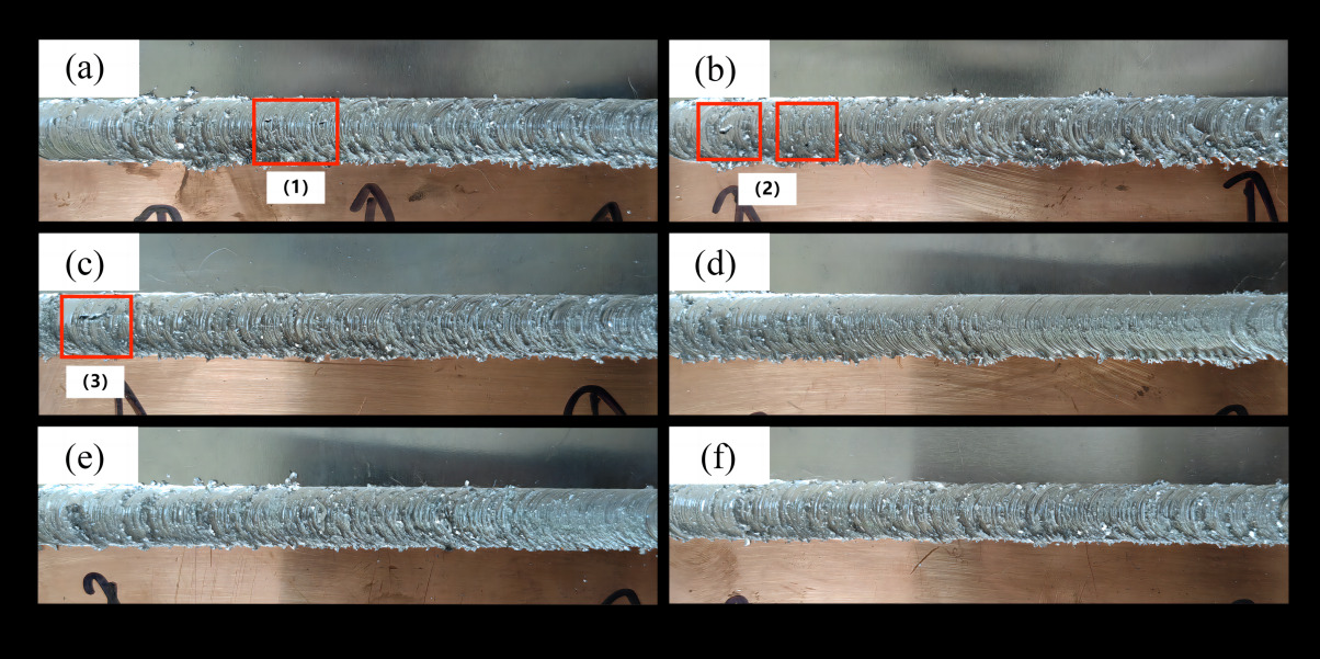
Figure 1. Welding seam renderings at different rotation speeds. (welding speed:70mm/min; rotation speeds: a. 600rpm; b. 700rpm; c. 800rpm; d. 900rpm; e. 1000rpm; f. 1100rpm)
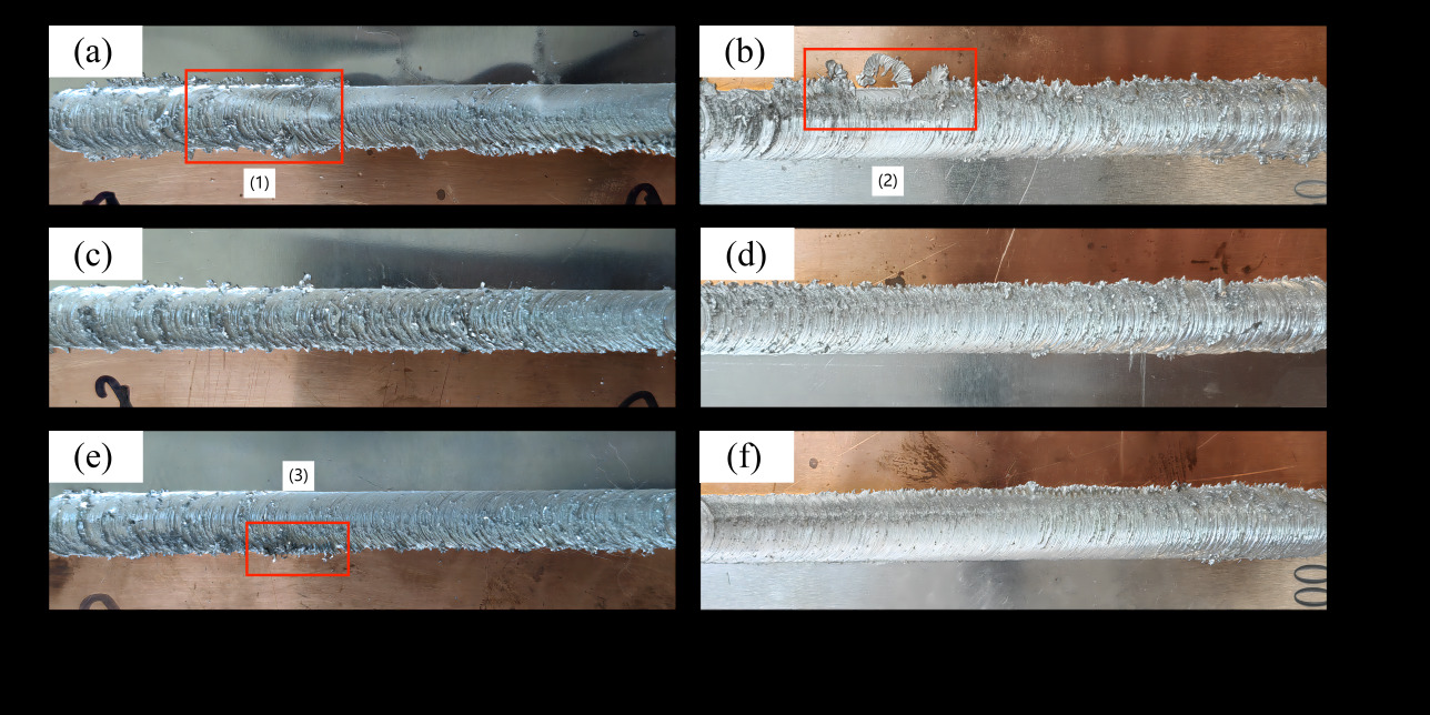
Figure 2. Welding seam renderings at different welding speeds ( rotation speed: 1000rpm; welding speed: a. 50mm/min; b. 60mm/min; c. 70mm/min; d. 80mm/min; e. 90mm/min; f. 100mm/min)
3.2 Tensile performance
Figure 3 illustrates the effect of rotation speed on the tensile strength of the welded joint. As the rotation speed increases, the heat input gradually intensifies, enhancing the metal's flowability. The increased plasticized material promotes thorough melting and plastic deformation in the weld seam. Simultaneously, the stirring effect becomes more pronounced, aiding in the formation of a more uniform microstructure, thereby enhancing the tensile strength of the welded joint. However, excessively high rotation speeds lead to localized overheating, resulting in uneven structural formations, causing weld seam defects and a sharp decline in tensile strength.
Figure 4 presents the impact of welding speed on the tensile strength of the welded joint, with a fixed rotation speed of 1000rpm. With increasing welding speed, the overall tensile strength of the welded joint shows an initial increase followed by a decrease in trend. At ω=1000rpm and v=70mm/min, the tensile strength reaches its peak at 89MPa, representing 84.76% of the tensile strength of 1060 aluminum. The lowest tensile strength occurs at ω=1000rpm and v=95mm/min, measuring 71MPa. When the welding speed is too high, the stirring pin's working time per unit area is too short, resulting in insufficient generation of frictional heat. This decreases the plastic flowability of the weld metal and severely hinders mutual diffusion at the metal interface. As a result, the interface bonding strength decreases, making the welded joint prone to crack formation and rapid expansion upon tension, exhibiting brittle fracture. A noticeable improvement in tensile strength is observed when the welding speed decreases to below 80mm/min. At this point, the increased welding heat input enhances the flowability of the weld metal, significantly strengthening the interface bonding strength. Moreover, the interface strength between copper and aluminum surpasses the strength of the aluminum side, often leading to fractures on the aluminum side. Due to aluminum's good plasticity and ductility, the fractured part undergoes plastic deformation and necking, resulting in the joint's fracture in a ductile manner.
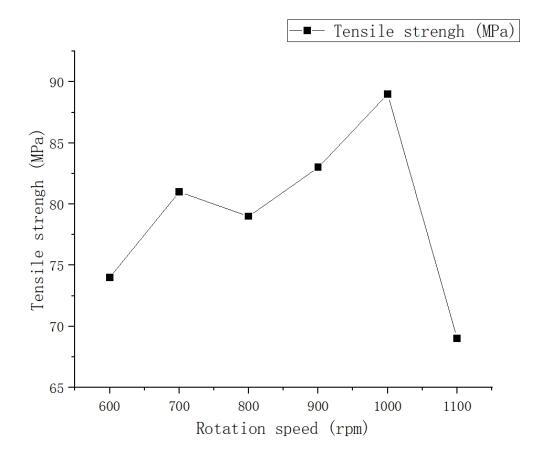
Figure 3. Effect of rotation speed on tensile strength of welded joints at 70mm/min welding speed
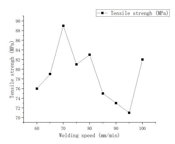
Figure 4. Effect of welding speed on tensile strength of welded joints at 1000rpm rotation speed
3.3 Microhardness
Figure 5 presents the results of microhardness tests at different rotation speeds. The hardness is highest in the weld nugget zone, followed by the heat-affected zone (HAZ), and the base material zone exhibits the lowest hardness. The microhardness decreases initially from the weld nugget zone to the HAZ and then increases from the HAZ to the heat-affected zone and further to the base material zone. Figure 6 displays the microhardness test results at different welding speeds, showing that as the welding speed decreases, the average hardness in the welded joint area exhibits a trend of initially decreasing and then increasing. The hardness distribution in the weld seam area is uneven in the figure, with points exceeding the hardness of the copper base material. This uneven distribution is attributed to the uneven formation of copper-aluminum intermetallic compounds during the welding process. Research by Ouyang et al. [12] indicates that the hardness of copper-aluminum intermetallic compounds can reach up to 760Hv.
Analyzing Figures 5 and 6 collectively reveals that rotation speed has a more significant impact on the hardness in the weld seam area. Although changing both rotation speed and welding speed can control the heat input, they determine different factors during the welding process. rotation speed and welding speed respectively determine the peak temperature and heating time in the friction stir welding heat cycle. Compared to heating time, the peak temperature has a more pronounced effect on the material's degree of softening [13].
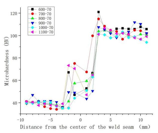
Figure 5. Effect of rotation speed on microhardness of welding joint at 70mm/min welding speed
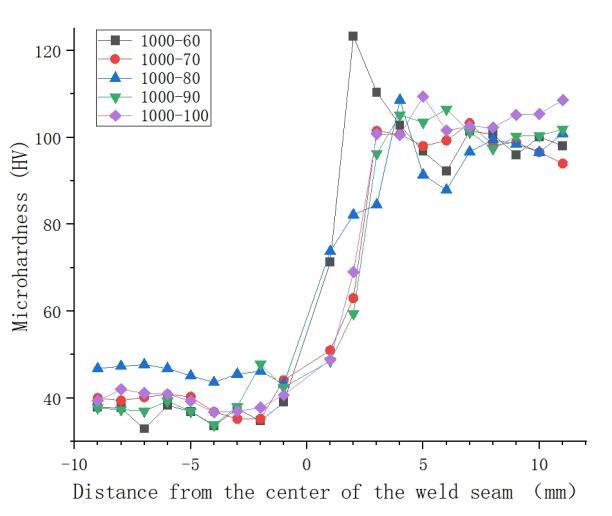
Figure 6. Effect of welding speed on microhardness of welded joints under 1000rpm rotation speed
3.4 Welding parameter process window
Figure 7 illustrates the contour map of tensile strength for the welded joints under various parameters. Combining this with the weld seam morphology discussed in Section 2.1, it is evident that heat input is the primary factor influencing weld seam formation. Adjusting rotation speed and welding speed can control the heat input within a certain range during the welding process. However, rotation speed and welding speed play decisive roles in determining the peak temperature and heating time during the welding process, thereby affecting the mechanical performance of the weld seam. Figure 7 indicates that under different welding parameters, well-formed and high-tensile-strength welded joints can be obtained. Therefore, it is possible to establish the process window for friction stir welding of 1060 aluminum and T2 copper, as depicted in Figure 8.
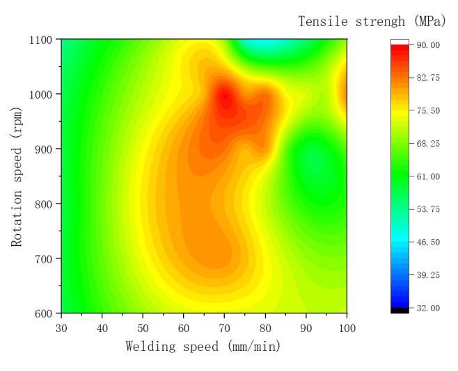
Figure 7. Cloud diagram of tensile strength of welded joints under various parameters
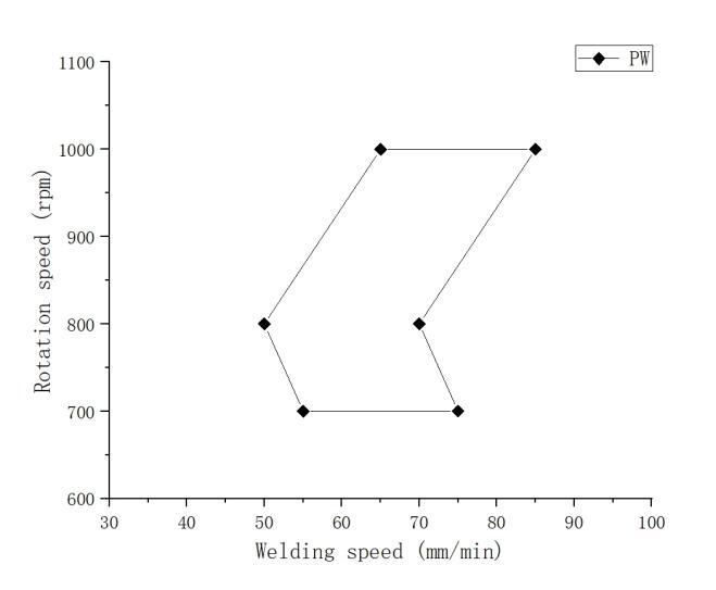
Figure 8. Friction stirs welding process parameter window
3.5 Electrochemical corrosion
Figure 9 presents the potentiodynamic polarization curves of the welded joints under different rotation speeds. The electrochemical parameters obtained using the Tafel extrapolation method are listed in Table 3. The corrosion potential for 1060 aluminum is -1.167V and T2 copper is -0.263V, indicating superior corrosion resistance for T2 copper, followed by the welded joint, and 1060 aluminum exhibits the poorest corrosion resistance. Under the premise of a welding speed of 70mm/min, the corrosion current density is similar for all groups. The highest corrosion potential is observed at a rotation speed of 1000rpm, indicating the best overall corrosion resistance.
Figure 10 illustrates the potentiodynamic polarization curves of the welded joints under different welding speeds, and the corresponding electrochemical parameters are presented in Table 2. At a rotation speed of 1000rpm, the corrosion current density is similar, with a corrosion potential of -0.616V and a corrosion current density of -4.332μA/cm² at a welding speed of 70mm/min, demonstrating better corrosion resistance. Combining the data from Tables 2.1 and 2.2, the optimal corrosion resistance for the welded joint is achieved at a rotation speed of 1000rpm and a welding speed of 70mm/min.
When fixing the welding speed, the corrosion potential gradually increases on both sides of 1000rpm rotation speed, forming a "V"-shaped trend. When fixing the rotation speed, the corrosion potential gradually increases on both sides of the welding speed at 70mm/min, showing a "V"-shaped trend, with no clear trend observed in the corrosion current. The electrochemical properties are related to the copper and aluminum structures in the weld seam and are also influenced by the distribution of second phases. The distribution of second phases may cause differences in local electrochemical reactions, making some areas more susceptible to corrosion, leading to higher corrosion currents in regions with second-phase distribution. In regions with localized corrosion due to second-phase differences, the corrosion potential may decrease, and the corrosion current may increase. In certain cases, the second phase may also have a corrosion-inhibiting effect, forming a protective film or barrier, thereby reducing the overall corrosion potential and corrosion current.
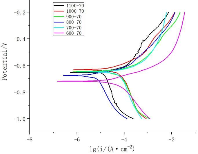
Figure 9. Polarization curves of weld nugget area at different rotation speeds (welding speed:70mm/min)
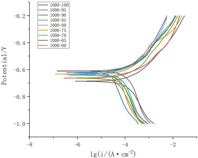
Figure 10. Polarization curves of the weld nugget area at different welding speeds (rotation speed: 1000rpm)
Table 3. Corrosion potential and corrosion current density in the weld area at different rotation speeds
rotation speeds(rpm) |
welding speeds (mm/min) |
Corrosion potential (Ecorr/V) |
corrosion current density (Ecorr/μA·cm²) |
600 |
70 |
-0.707 |
-4.363 |
700 |
-0.696 |
-4.099 |
|
800 |
-0.738 |
-4.993 |
|
900 |
-0.679 |
-4.132 |
|
1000 |
-0.616 |
-4.332 |
|
1100 |
-0.751 |
-4.640 |
Table 4. Corrosion potential and corrosion current density in the weld area at different welding speeds
rotation speeds(rpm) |
welding speeds (mm/min) |
Corrosion potential (Ecorr/V) |
corrosion current density (Ecorr/μA·cm²) |
1000 |
60 |
-0.688 |
-4.183 |
65 |
-0.621 |
-4.079 |
|
70 |
-0.616 |
-4.332 |
|
75 |
-0.651 |
-4.307 |
|
80 |
-0.647 |
-4.207 |
|
85 |
-0.643 |
-4.389 |
|
90 |
-0.675 |
-4.484 |
|
95 |
-0.688 |
-4.336 |
|
100 |
-0.697 |
-4.024 |
Figure 11 depicts the AC impedance spectrum at a rotation speed of 1000rpm and a welding speed of 70mm/min. The Nyquist plot, characterizing the inductive properties with two semicircles, indicates the presence of two-time constants. The high-frequency capacitive arc represents the charge transfer resistance and double-layer capacitance, constituting the surface polarization reaction of the electrode. The corrosion products of lightly chlorinated aluminum and aluminum oxide form on the aluminum surface in the electrolyte containing chloride ions, hindering charge transfer. The low-frequency inductive arc is associated with the continuous adsorption and desorption processes of reaction products on the electrode surface during the reduction of metal ions. This phenomenon correlates with the changing composition structure of the oxide film and the surface structure [14-15]. In the Bode plot, this is reflected in the existence of two-time constants in the phase angle versus frequency curve.
During the initial stage of corrosion, in regions with significant surface defects, second-phase distribution, or residual stresses, aluminum undergoes active dissolution. As the potential increases, the polarization current density decreases, and a protective solid corrosion product forms on the aluminum surface, creating an oxide film that induces a passive state. Subsequently, the increase in potential causes the gradual dissolution of the passivation film, exhibiting pitting corrosion tendencies. However, the passivation film rapidly repairs itself. Meanwhile, the accumulation of corrosion products isolates the matrix from the corrosive solution, prompting the surface of the matrix to repassivate and form an oxide film, with a more robust bond to the matrix. In this process, the simultaneous occurrence of the breakdown and repair mechanisms of the passivation layer results in the coexistence of multiphase capacitance. Studies [16] suggest that during the initiation of pitting corrosion, the polarization resistance significantly decreases. In the induction period of pitting corrosion, the Nyquist plot of the impedance spectrum shows an inductive component in the low-frequency region, consistent with the shape of the low-frequency inductive arc in Figure 12.
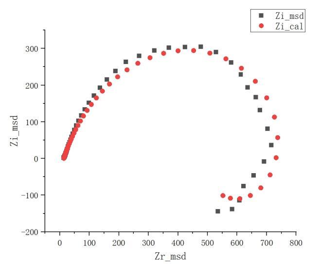
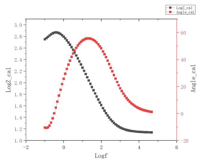
Figure 11. Nyquist diagram & Bode diagram of the weld area when the rotation speed is 1000rpm and the welding speed is 70mm/min.
4. Conclusion
(1) The application of the Friction Stir Welding (FSW) process successfully achieved an effective connection between 2mm thick 1060 aluminum and T2 copper dissimilar metal sheets in a butt joint configuration. Furthermore, a parameter window for the FSW welding process was established.
(2) Optimal welding joints were obtained when T2 copper was placed on the advancing side, with a rotation speed of 1000rpm, welding speed of 70mm/min, an offset of 1.2mm (towards the aluminum side), a tilt angle of 1.5° for the stirring pin, and a plunge depth of 0.2mm. Under these conditions, the tensile strength of the joint reached 84.76% of that of 1060 aluminum, demonstrating good corrosion resistance.
(3) The corrosion potential of the copper-aluminum composite joint falls between the potentials of the individual base metals, indicating both positive and negative influences of second-phase distribution on the corrosion behavior.
References:
1 Li, G., & Liu, X. (2020). Research Status Review of Lightweight Technology in Automobiles. Materials Science and Technology, 28(5), 47-61.
2 Zhang, Q., Ye, P., Yang, Z., et al. (2019). Application Status and Development Trends of Lightweight Connection Technology in Automobiles. Nonferrous Metal Processing, 48(1), 1-9.
3 Chen, Y., Xue, S., Wang, B., et al. (2019). Current Development and Future of Welding Technology for Lightweight Automobiles. Materials Reports, 33(S2), 431-440.
4 Huang, Y., Wang, Y., Wan, L., et al. (2016). Material-flow behavior during friction-stir welding of 6082-T6 aluminum alloy. International Journal of Advanced Manufacturing Technology, 87(1-4), 1-9.
5 Hamed, J. A. (2017). Effect of welding heat input and post-weld aging time on microstructure and mechanical properties in dissimilar friction stir welded AA7075-AA5086. Transactions of Nonferrous Metals Society of China, 27(8), 1707-1715.
6 Madhusudan, M., Sunil, K., Shridhar, K., et al. (2020). Behavioral studies of process parameters and transient numerical analysis on friction stir welded dissimilar alloys. *Materials Today: Proceedings.
7 Mehta, K. P., & Badheka, V. J. (2016). A review on dissimilar friction stir welding of copper to aluminum: process, properties, and variants. Materials & Manufacturing Processes, 31(3), 233-254.
8 Dong, F. (2011). Research on Friction Stir Welding Process of Aluminum/Copper Dissimilar Materials (Master's thesis). Nanjing University of Aeronautics and Astronautics.
9 Mao, Y. Q., Ke, L. M., Liu, F. C., et al. (2016). Investigations on Temperature Distribution, Microstructure Evolution, and Property Variations along Thickness in Friction Stir Welded Joints for Thick AA7075-T6 Plates. International Journal of Advanced Manufacturing Technology, 86(1), 141-154.
10 Zhang, C., & Wan, Z. (2020). Influence of Rotation Speed and Welding Speed on the Formation of Aluminum-Copper Dissimilar Material Friction Stir Welded Joints. Journal of Precision Engineering, 12(3), 154-159.
11 Zhen, Y. Q., Liu, X. C., Shen, Z. K., et al. (2020). Experimental Characterization of Material Flow in Friction Stir Welding: Current Research Status. Chinese Journal of Mechanical Engineering, 56(6), 184-192.
12 Ouyang, J., Yarrapareddy, E., & Kovacevic, R. (2006). Microstructural evolution in the friction stir welded 6061 aluminum alloy (T6-temper condition) to copper. Journal of Materials Processing Technology, 172(1), 110-122.
13 Sato, Y. S., Urata, M., & Kokawa, H. (2002). Parameters controlling microstructure and hardness during friction-stir welding of precipitation-hardenable aluminum alloy 6063. Metallurgical & Materials Transactions A, 33(3), 625-635.
14 Amirudin, A., & Thierry, D. (1996). Corrosion mechanisms of phosphated zinc layers on steel as substrates for automotive coatings. Progress in Organic Coatings, 28(1), 59-75.
15 Cachet, C., Ganne, F., Joiret, S., et al. (2002). EIS investigation of zinc dissolution in aerated sulphate medium. Part II: Zinc coatings. Electrochimica Acta, 47(21), 3409-3422.
16 Gouveia-Caridade, C., Pereira, M. I. S., & Brett, C. M. A. (2004). Electrochemical noise and impedance study of aluminum in weakly acid chloride solution. Electrochimica Acta, 49(5), 785-793.
References
[1]. Li, G., & Liu, X. (2020). Research Status Review of Lightweight Technology in Automobiles. Materials Science and Technology, 28(5), 47-61.
[2]. Zhang, Q., Ye, P., Yang, Z., et al. (2019). Application Status and Development Trends of Lightweight Connection Technology in Automobiles. Nonferrous Metal Processing, 48(1), 1-9.
[3]. Chen, Y., Xue, S., Wang, B., et al. (2019). Current Development and Future of Welding Technology for Lightweight Automobiles. Materials Reports, 33(S2), 431-440.
[4]. Huang, Y., Wang, Y., Wan, L., et al. (2016). Material-flow behavior during friction-stir welding of 6082-T6 aluminum alloy. International Journal of Advanced Manufacturing Technology, 87(1-4), 1-9.
[5]. [5] Hamed, J. A. (2017). Effect of welding heat input and post-weld aging time on microstructure and mechanical properties in dissimilar friction stir welded AA7075-AA5086. Transactions of Nonferrous Metals Society of China, 27(8), 1707-1715.
[6]. Madhusudan, M., Sunil, K., Shridhar, K., et al. (2020). Behavioral studies of process parameters and transient numerical analysis on friction stir welded dissimilar alloys. *Materials Today: Proceedings.
[7]. Mehta, K. P., & Badheka, V. J. (2016). A review on dissimilar friction stir welding of copper to aluminum: process, properties, and variants. Materials & Manufacturing Processes, 31(3), 233-254.
[8]. Dong, F. (2011). Research on Friction Stir Welding Process of Aluminum/Copper Dissimilar Materials (Master's thesis). Nanjing University of Aeronautics and Astronautics.
[9]. Mao, Y. Q., Ke, L. M., Liu, F. C., et al. (2016). Investigations on Temperature Distribution, Microstructure Evolution, and Property Variations along Thickness in Friction Stir Welded Joints for Thick AA7075-T6 Plates. International Journal of Advanced Manufacturing Technology, 86(1), 141-154.
[10]. Zhang, C., & Wan, Z. (2020). Influence of Rotation Speed and Welding Speed on the Formation of Aluminum-Copper Dissimilar Material Friction Stir Welded Joints. Journal of Precision Engineering, 12(3), 154-159.
[11]. Zhen, Y. Q., Liu, X. C., Shen, Z. K., et al. (2020). Experimental Characterization of Material Flow in Friction Stir Welding: Current Research Status. Chinese Journal of Mechanical Engineering, 56(6), 184-192.
[12]. Ouyang, J., Yarrapareddy, E., & Kovacevic, R. (2006). Microstructural evolution in the friction stir welded 6061 aluminum alloy (T6-temper condition) to copper. Journal of Materials Processing Technology, 172(1), 110-122.
[13]. Sato, Y. S., Urata, M., & Kokawa, H. (2002). Parameters controlling microstructure and hardness during friction-stir welding of precipitation-hardenable aluminum alloy 6063. Metallurgical & Materials Transactions A, 33(3), 625-635.
[14]. Amirudin, A., & Thierry, D. (1996). Corrosion mechanisms of phosphated zinc layers on steel as substrates for automotive coatings. Progress in Organic Coatings, 28(1), 59-75.
[15]. Cachet, C., Ganne, F., Joiret, S., et al. (2002). EIS investigation of zinc dissolution in aerated sulphate medium. Part II: Zinc coatings. Electrochimica Acta, 47(21), 3409-3422.
[16]. Gouveia-Caridade, C., Pereira, M. I. S., & Brett, C. M. A. (2004). Electrochemical noise and impedance study of aluminum in weakly acid chloride solution. Electrochimica Acta, 49(5), 785-793.
Cite this article
Chen,Y.;Chen,J. (2024). Mechanical properties and corrosion resistance study of dissimilar metal thin sheet friction stir welded joints. Advances in Engineering Innovation,6,21-31.
Data availability
The datasets used and/or analyzed during the current study will be available from the authors upon reasonable request.
Disclaimer/Publisher's Note
The statements, opinions and data contained in all publications are solely those of the individual author(s) and contributor(s) and not of EWA Publishing and/or the editor(s). EWA Publishing and/or the editor(s) disclaim responsibility for any injury to people or property resulting from any ideas, methods, instructions or products referred to in the content.
About volume
Journal:Advances in Engineering Innovation
© 2024 by the author(s). Licensee EWA Publishing, Oxford, UK. This article is an open access article distributed under the terms and
conditions of the Creative Commons Attribution (CC BY) license. Authors who
publish this series agree to the following terms:
1. Authors retain copyright and grant the series right of first publication with the work simultaneously licensed under a Creative Commons
Attribution License that allows others to share the work with an acknowledgment of the work's authorship and initial publication in this
series.
2. Authors are able to enter into separate, additional contractual arrangements for the non-exclusive distribution of the series's published
version of the work (e.g., post it to an institutional repository or publish it in a book), with an acknowledgment of its initial
publication in this series.
3. Authors are permitted and encouraged to post their work online (e.g., in institutional repositories or on their website) prior to and
during the submission process, as it can lead to productive exchanges, as well as earlier and greater citation of published work (See
Open access policy for details).
References
[1]. Li, G., & Liu, X. (2020). Research Status Review of Lightweight Technology in Automobiles. Materials Science and Technology, 28(5), 47-61.
[2]. Zhang, Q., Ye, P., Yang, Z., et al. (2019). Application Status and Development Trends of Lightweight Connection Technology in Automobiles. Nonferrous Metal Processing, 48(1), 1-9.
[3]. Chen, Y., Xue, S., Wang, B., et al. (2019). Current Development and Future of Welding Technology for Lightweight Automobiles. Materials Reports, 33(S2), 431-440.
[4]. Huang, Y., Wang, Y., Wan, L., et al. (2016). Material-flow behavior during friction-stir welding of 6082-T6 aluminum alloy. International Journal of Advanced Manufacturing Technology, 87(1-4), 1-9.
[5]. [5] Hamed, J. A. (2017). Effect of welding heat input and post-weld aging time on microstructure and mechanical properties in dissimilar friction stir welded AA7075-AA5086. Transactions of Nonferrous Metals Society of China, 27(8), 1707-1715.
[6]. Madhusudan, M., Sunil, K., Shridhar, K., et al. (2020). Behavioral studies of process parameters and transient numerical analysis on friction stir welded dissimilar alloys. *Materials Today: Proceedings.
[7]. Mehta, K. P., & Badheka, V. J. (2016). A review on dissimilar friction stir welding of copper to aluminum: process, properties, and variants. Materials & Manufacturing Processes, 31(3), 233-254.
[8]. Dong, F. (2011). Research on Friction Stir Welding Process of Aluminum/Copper Dissimilar Materials (Master's thesis). Nanjing University of Aeronautics and Astronautics.
[9]. Mao, Y. Q., Ke, L. M., Liu, F. C., et al. (2016). Investigations on Temperature Distribution, Microstructure Evolution, and Property Variations along Thickness in Friction Stir Welded Joints for Thick AA7075-T6 Plates. International Journal of Advanced Manufacturing Technology, 86(1), 141-154.
[10]. Zhang, C., & Wan, Z. (2020). Influence of Rotation Speed and Welding Speed on the Formation of Aluminum-Copper Dissimilar Material Friction Stir Welded Joints. Journal of Precision Engineering, 12(3), 154-159.
[11]. Zhen, Y. Q., Liu, X. C., Shen, Z. K., et al. (2020). Experimental Characterization of Material Flow in Friction Stir Welding: Current Research Status. Chinese Journal of Mechanical Engineering, 56(6), 184-192.
[12]. Ouyang, J., Yarrapareddy, E., & Kovacevic, R. (2006). Microstructural evolution in the friction stir welded 6061 aluminum alloy (T6-temper condition) to copper. Journal of Materials Processing Technology, 172(1), 110-122.
[13]. Sato, Y. S., Urata, M., & Kokawa, H. (2002). Parameters controlling microstructure and hardness during friction-stir welding of precipitation-hardenable aluminum alloy 6063. Metallurgical & Materials Transactions A, 33(3), 625-635.
[14]. Amirudin, A., & Thierry, D. (1996). Corrosion mechanisms of phosphated zinc layers on steel as substrates for automotive coatings. Progress in Organic Coatings, 28(1), 59-75.
[15]. Cachet, C., Ganne, F., Joiret, S., et al. (2002). EIS investigation of zinc dissolution in aerated sulphate medium. Part II: Zinc coatings. Electrochimica Acta, 47(21), 3409-3422.
[16]. Gouveia-Caridade, C., Pereira, M. I. S., & Brett, C. M. A. (2004). Electrochemical noise and impedance study of aluminum in weakly acid chloride solution. Electrochimica Acta, 49(5), 785-793.