


1. Introduction
1.1. Introduction to barley and its harvesting
Barley is the staple food of the Tibetan people, characterized by strong cold resistance, short growth period, high yield, early maturity, and wide adaptability. Its main production areas in China include Tibet, Qinghai, Sichuan, and Yunnan. Barley is a highly adaptable crop, especially suited to cold and barren conditions.
Barley harvesting typically takes place from September to October each year, employing primarily two methods: large-scale mechanized operations and manual harvesting. Due to terrain conditions and scale limitations, individual farmers in Tibet’s high-altitude mountainous regions lack suitable machinery for barley harvesting. Consequently, they rely on manual labor, using sickles to cut the stalks and bundling them into sheaves. After harvesting, the sheaves are transported home by livestock for sun drying. This manual process results in high labor intensity and time consumption [1].
1.2. Purpose and significance of research on plateau mountain barley harvesters
The unique terrain of Tibet, coupled with scarce arable land and inadequate attention to agricultural mechanization, results in low agricultural productivity. Most farmers adhere to traditional methods for barley cultivation and harvesting, leading to slower development in these regions. [2-3]
Plateau mountain barley harvesters are small-scale agricultural machinery characterized by lightweight, flexibility, low cost, ease of use, and utilization of clean energy. On one hand, they address the limitations of large machinery in small-scale production, making them suitable for use in Tibet’s plateau regions. On the other hand, the development of such small-scale agricultural machinery fills a gap where agricultural machinery enterprises have previously invested less, thereby promoting the modernization of China’s agriculture.
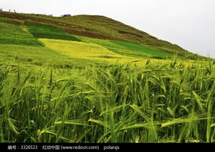
Figure 1. Barley planted on sloping farmland
2. Current development of barley harvesters domestic and international
The plateau hand-held cutting and sun drying machine is a type of machinery used for harvesting and drying crops, widely employed in plateau regions. With the continuous advancement of agricultural mechanization, the structural design of plateau hand-held cutting and sun drying machines has become a significant research topic. This paper reviews recent literature related to the structural design of plateau hand-held cutting and sun drying machines, aiming to provide references and insights for research in this field.
2.1. Domestic development of barley harvesters
The mechanization level of large-scale barley cultivation in China has been increasing, leading to higher yields annually. However, the mechanization of small-scale and dispersed barley planting still requires improvement. Mechanization is often neglected in cases of small-scale planting. Barley is utilized as a staple food crop in China, and some small harvesters originally designed for common grains have been adapted for barley harvesting after modifications by certain companies. While these efforts have shown some effectiveness, they are primarily suitable for medium-scale cultivation and face challenges in terrain such as hillsides and terraced fields. Common models include Zhonglian Guwang TB60 and Kubota 4LZ-2.5 among others.
2.2. International development of barley harvesters
In developed countries, agricultural mechanization levels are generally high, with rich experience and technological advantages in agricultural machinery research, development, and application. These countries typically employ large-scale, high-performance harvesters for efficient harvesting and processing in extensive agricultural production. However, the development of barley harvesters and similar niche crop harvesters is still in its early stages internationally. This is mainly due to the limited cultivation areas and relatively small market demand for barley and similar crops, resulting in insufficient research and investment. Nevertheless, with the advancement of China’s agricultural modernization, agricultural mechanization, and ongoing agricultural technology research and development, it is anticipated that more harvesters suitable for barley and similar niche crops will emerge in the future.
3. 3 Design proposal of plateau hand-held barley cutting and sun drying machine
3.1. Determination of basic parameters
Considering the narrow mountain paths, lateral and longitudinal tilting of the entire machine, and turning radius, the harvester width is planned to be between 0.8m and 1m, total length within 1.8m, and ground clearance approximately 0.5m. Additionally, for comfortable operation, the design takes into account the average height of Chinese men/women (175cm/163cm), with the height at the elbow around 0.61H = 106.75cm/99.43cm. The height of handlebars, control buttons, and other devices is designed to be approximately 90cm to 80cm.
3.2. Chassis design
3.2.1. Drive system design
Based on the layout of traditional small-scale cutting and drying machines, the chassis design aims for strong maneuverability and good operability. It adopts a front layout with two active large wheels and a rear support with one passive universal wheel. The front wheels are two 12-inch rubber-toothed tires driven by hub motors. The rear wheel is a 4-inch unpowered universal wheel. A 24V 500W reduction motor is selected for the hub motor. The tire diameter is 400 \( mm \) , and the typical speed at 24 \( V \) voltage is 6km/h. The maximum torque of the hub motor is 80 \( N·m \) .
3.2.1.1. Chassis drive force
The chassis is powered by the torque output from the hub motor. Since the drive wheel is directly driven by the hub motor, transmission efficiency is high, and transmission losses are negligible. The torque \( {T_{t}} \) acting on the drive wheel produces a linear velocity, generating a circumferential force \( {F_{0}} \) on the ground, where \( {F_{t}} \) , the reactive force of \( {F_{0}} \) , represents the driving force of the chassis [4].
\( {F_{t}}=\frac{{T_{t}}}{r} \) (1)
Where:
\( {F_{t}} \) - Chassis driving force, N;
\( {T_{t}} \) - Torque acting on the drive wheel, N·m.
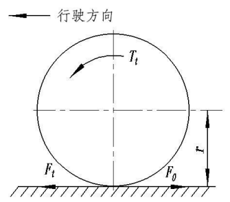
Figure 2. Chassis driving force
3.2.1.2. Travel resistance
During the operation of the harvester, it needs to overcome various resistances, including frictional resistance and inertial resistance generated by the mechanical structure of the chassis during movement: rolling resistance \( {F_{f}} \) , acceleration resistance \( {F_{j}} \) , air resistance \( {F_{w}} \) , and on slopes, it also needs to overcome the downhill force of gravity \( {F_{i}} \) . Thus, the total resistance encountered by the harvester during travel is expressed as:
\( ΣF={F_{f}}+{F_{i}}+{F_{j}}+{F_{w}} \) (2)
Where:
\( {F_{f}} \) - Rolling resistance, N;
\( {F_{j}} \) - Acceleration resistance, N;
\( {F_{i}} \) - Slope resistance, N;
\( {F_{w}} \) - Air resistance, N.
1) Rolling Resistance
When the harvester travels on a flat road surface, there are normal and tangential interaction forces between the drive wheels and the road surface. As shown in Figure 3, the contact area of the tire undergoes deformation.
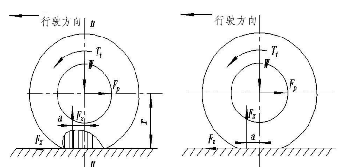
Figure 3. Force diagram of drive wheel rolling on a flat road surface
The normal reaction force \( {F_{z}} \) at the contact area of the tire with the road surface causes a moment due to the delayed track of the tire, shifting the point of force application forward by a distance a. Therefore, a rolling torque \( {T_{f}} \) is generated on the drive wheel:
\( {T_{f}}={F_{z}}\cdot a \) (3)
Where:
\( {T_{f}} \) - Rolling torque on the drive wheel, N·m;
\( {F_{z}} \) - Normal reaction force at the drive wheel-ground interface, N.
Thus, the actual driving force \( {F_{x}} \) that propels the harvester forward on flat ground is the difference between the motor driving force \( {T_{t}} \) and the rolling resistance \( {T_{f}} \) , divided by the radius \( r \) :
\( {F_{x}}=\frac{{T_{t}}-{T_{f}}}{r} \) (4)
2) Slope Resistance
When the harvester travels uphill on a slope, the downhill force of its own weight is the slope resistance encountered by the harvester, as depicted in Figure 4. Specifically:
\( {F_{i}}=Gsin{α} \) (5)
Where:
G - Gravity acting on the harvester, N.
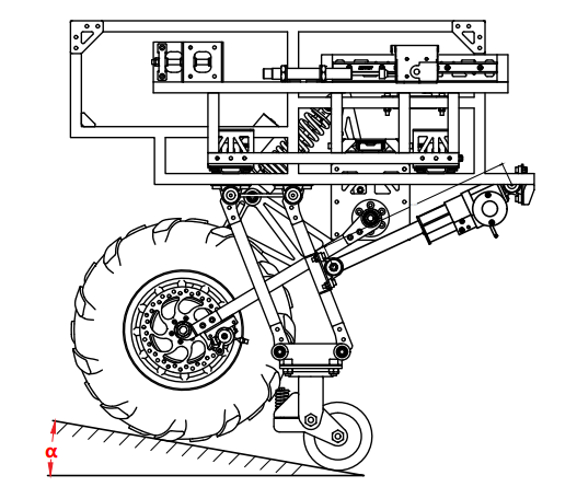
Figure 4. Force state of the harvester chassis traveling on a slope
Since the maximum speed of the harvester is 6km/h and it moves slowly, air resistance and inertial resistance are negligible. Based on the analysis of various resistances, the equilibrium equation for harvester travel is:
\( {F_{t}}={F_{f}}+{F_{i}} \) (6)
Thus,
\( \frac{{T_{t}}}{r}=Gfcos{α}+Gsin{α} \) (7)
The total weight of the vehicle is approximately 70 \( kg \) (including the battery). Due to uneven economic development in Tibetan areas, many regions lack hardened cement roads. Therefore, the calculation adopts the rolling friction coefficient corresponding to dry sandy soil surfaces. The front wheels use toothed tires, and the rear wheels use narrow universal wheels, both calculated based on the rolling friction coefficient between toothed tires and the ground [4].
According to relevant tables, the rolling friction coefficient \( f \) of pneumatic rubber tires on dry sandy soil surfaces is approximately 0.3. For calculation purposes, the slope α is taken as 20°, and the gravitational acceleration \( g \) is taken as 9.8 \( \frac{m}{{s^{2}}} \) . Calculating from equation (7):
\( {T_{f}}=mg(sin{α}+fcos{a})r=70×9.8×(sin{20°}+0.3×cos{20°})×0.2=85.6N·m \)
A single hub motor can output a torque of \( 80N\cdot m \) , and the harvester uses two hub motors in total, thus:
\( {T_{t}}=160N\cdot m \gt {T_{t}}=85.6N\cdot m \)
Based on the above calculations, the harvester has sufficient power to travel in high-altitude mountainous regions.
Table 1. Rolling Friction Coefficient Table
GROUND | \( f \) | \( φ \) | ||
Steel or cast-iron wheel | Pneumatic tire wheel | Steel or cast-iron wheel | Pneumatic tire wheel | |
Dry sand soil Wet sand soil Grassland | 0.3 0.14 | 0.2 0.16 0.08 | 0.2 0.8~1 | 0.3 0.5~0.7 |
Rolling resistance coefficient \( f \) and adhesion coefficient \( φ \)
3.2.2. Infinitely variable wheel track mechanism design
The road conditions in the Tibetan Plateau are complex and varied. To enable the vehicle to adapt to various road widths, we have developed an infinitely variable wheel track mechanism. As shown in Figure 5, the main body of this mechanism is a frame welded from stainless steel pipes. It incorporates two pairs of vertically mounted slides to form the telescopic mechanism, as illustrated in Figure 6. U-shaped sheet metal is welded to the frame, with the slide track installed on each side of the U-shaped sheet metal. One end of the slide is connected to the sheet metal piece through bolts to the wheel leg frame.
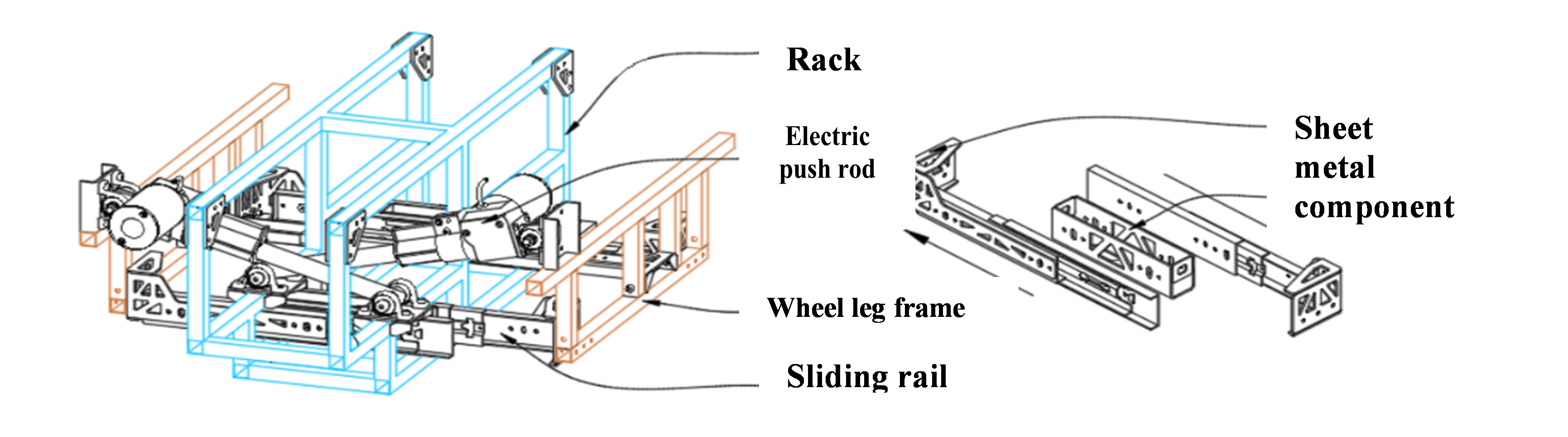
Figure 5. Variable wheel track mechanism Figure 6. Slide rail installation
The simplified diagram of the mechanism motion of the infinitely variable wheel track mechanism is shown in Figure 7. The structure employs a pair of electric actuators, with each actuator hinged to one side of the wheel leg frame via bearing housings, and to the main frame via another bearing housing. This arrangement allows the electric actuators to control the telescopic movement of the wheel leg frame on the slide rail, enabling adjustment of the wheel track within the range of \( 0.46m-0.67m \) , as depicted in Figure 7.
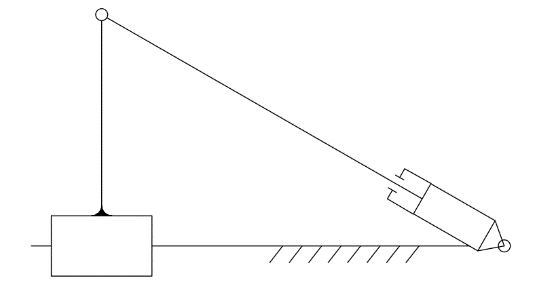
Figure 7. Simplified diagram of the infinitely variable wheel track mechanism (single side)
To ensure that the harvester maintains structural strength while incorporating the infinitely variable wheel track function, we made the following design considerations:
(1) The actuators and the frame form a truss structure. The selected electric actuators possess excellent self-locking capabilities. When both actuators are stationary, they form a truss structure with the central frame and the side wheel leg frame, providing the vehicle with higher strength and ensuring a tight connection between the side wheel leg frame and the central frame, as shown in Figure 8.
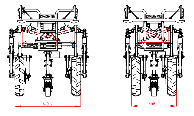
Figure 8. Maximum and minimum wheel tracks and truss structure schematic
(2) The electric actuators and the wheel axles are approximately aligned on the same straight line. When the actuators exert a force \( F \) to extend or retract, the tires on both sides experience frictional force \( {F^{ \prime }} \) from the ground in the opposite direction, as shown in Figure 9. If \( F \) and \( {F^{ \prime }} \) are not aligned on the same straight line, it will cause additional moments on the side wheel frame due to \( F \) and \( {F^{ \prime }} \) . If this moment is too large, it can lead to significant deformation of the side wheel frame relative to the central frame, affecting the harvester’s operation. By installing the actuators and wheel axles approximately on the same straight line, this moment can be reduced, minimizing its impact on the overall strength.
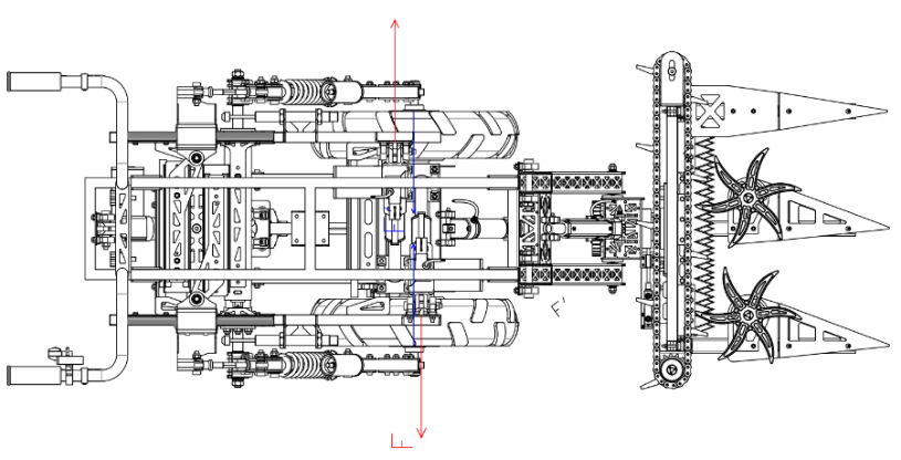
Figure 9. Force diagram on side wheel frame during variable wheel track
3.2.3. Design of tiltable suspension
To ensure the vehicle can travel more stably on slopes or mountainous terrain [5], we have designed a tiltable suspension mechanism that links the left and right wheels. It consists of a multi-link mechanism on the wheel legs and a linkage mechanism in the center of the vehicle body, as illustrated in Figure 10.
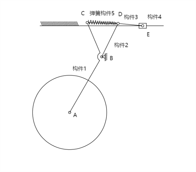
Figure 10. Schematic diagram of the wheel leg mechanism
To clearly explain the working principle of the tiltable suspension, it is divided into the following parts:
3.2.3.1. Composition and movement of the wheel leg mechanism
The wheel leg mechanism consists of a rubber wheel, sliding rail frame 0, link component 1, link component 2, link component 3, slider 4, and spring 5. When both wheels of the harvester are in contact with the ground, the slider 4 cannot move and is considered fixed to the frame. When there is stimulation on the rubber wheel from the ground, the rubber wheel lifts upward, causing link component 1 to rotate clockwise around hinge support B. Since the slider 4 is fixed and cannot slide, spring 5 begins to compress, absorbing the energy generated by the ground stimulation, thus completing the suspension damping process.
3.2.3.2. Composition and movement of the central linkage mechanism
When one side of the harvester’s wheels loses contact with the ground while the other side remains in contact, the slider 4 can move. The support force from the ground on the side in contact with the ground causes link component 1 to rotate clockwise around hinge support B. Because slider 4 can freely slide on the sliding rail, spring 5 is not compressed. Link component 1 and link component 2 rotate clockwise around hinge support B together with link 3, moving the slider 4 to the right along the sliding rail.
As slider 4 moves to the right or downward along the sliding rail, the motion is transmitted to the central linkage mechanism, depicted in schematic form in Figure 11. When slider 4 moves downward along the left sliding rail, the linear distance between slider 4 and slider 4’ changes during rotation. Therefore, sliding rail component 6 slides within its track, rotating counterclockwise around hinge support F. Subsequently, slider 4’ moves upward under the drive of sliding rail component 6.
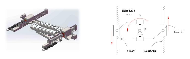
Figure 11. Schematic diagram and mechanism of the central linkage mechanism
Ultimately, slider 4’ moves in the opposite direction to slider 4. The direction of movement of the wheel leg mechanism on the side of slider 4’ will be opposite to that of the side with slider 4, causing the rubber wheel to move downward and make contact with the ground.
3.2.3.3. Function of hydraulic damping pistons on both sides
Although the tiltable suspension allows the harvester to maintain horizontal orientation on slopes, this structure enables free vertical movement of the harvester’s two wheels. When unassisted and with the vehicle slightly tilted, the force situation is illustrated in Figure 12. The vehicle is subjected to its own weight \( G \) and supporting forces \( {F_{N1}} \) and \( {F_{N2}} \) from the ground, causing moments \( {M_{1}} \) and \( {M_{2}} \) around the center of mass. Due to the vehicle’s tilt, gravity no longer passes through the midpoint between the two wheels, resulting in the need for the moments to balance in the plane:
\( {M_{1}}={M_{2}} \)
\( {F_{{N_{1}}}}≠{F_{{N_{2}}}} \) (8)
However, due to the presence of the interconnected linkage mechanism on both sides, the two support forces are always equal:
\( {F_{{N_{1}}}}={F_{{N_{2}}}}=\frac{G}{2} \) (9)
This imbalance in moments in the plane, \( {M_{1}} \lt {M_{2}} \) , causes the vehicle to tilt to the left. Even when operated manually to maintain balance between the left and right sides of the harvester, considerable physical effort is required. To address this issue, we have installed two hydraulic damping pistons at the front ends of sliders 4 and 4’.

Figure 12. Force situation diagram when unassisted on a slope
When the rubber wheels move vertically, slider 4 or 4’ will encounter their corresponding hydraulic damping pistons. Initially, the hydraulic damping pistons attract energy with low reaction force and then absorb energy smoothly with linear deceleration, achieving a smooth deceleration effect. The displacement-force diagram is shown in Figure 13. The deceleration effect of the hydraulic damping pistons is transmitted to the rubber wheels through various mechanisms, causing the height difference of the left and right rubber wheel axles to change at a slower rate, thereby preventing the harvester from tilting and improving its operational performance.
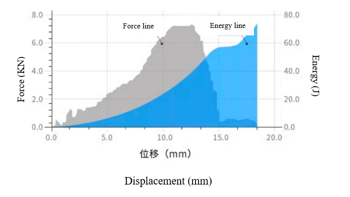
Figure 13. Displacement-force diagram of hydraulic damping pistons
The adjustable gear oil damping device features 10 gear positions with a \( 50mm \) stroke and maximum resistance of \( 160kg \) . Its thrust can be adjusted according to requirements.
Characteristics of Tiltable Suspension:
1) Stability and Shock Absorption Effect
2) Adaptability and Flexibility
3) Function of Linkage Mechanism
4) Wide Applicability
3.2.4. Design of variable ground clearance mechanism
Due to the harvester’s substantial weight and its design for manual operation, it is particularly difficult to control when driving on slopes, especially downhill. Additionally, when the harvester operates on sloped farmland, the front and rear wheel pressures differ, as depicted in Figure 14, potentially causing soil compaction or damage [4, 7].
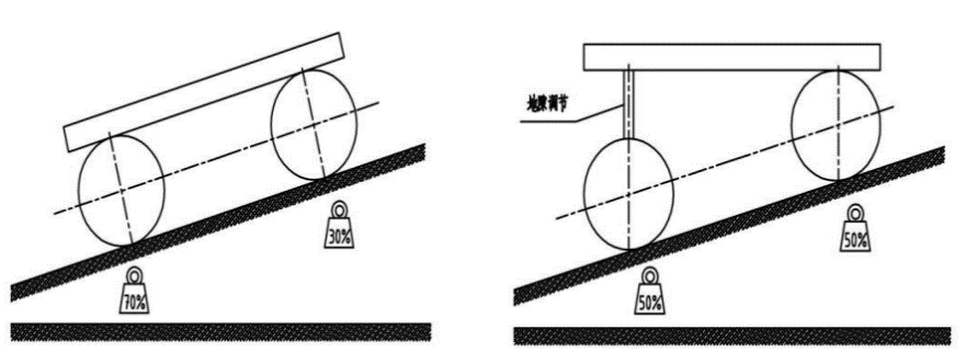
Figure 14. Pressure distribution on front and rear wheels of two harvesters on a slope
To address this issue, we propose a linkage mechanism that allows for the adjustment of rear wheel lift. It utilizes a maximum stroke of \( 100mm \) and a maximum thrust of \( 1000N \) provided by an electric push rod. This mechanism drives the linkage, causing the small wheels to swing around the frame, thereby adjusting the ground clearance. The functional effect is illustrated in Figure 15.
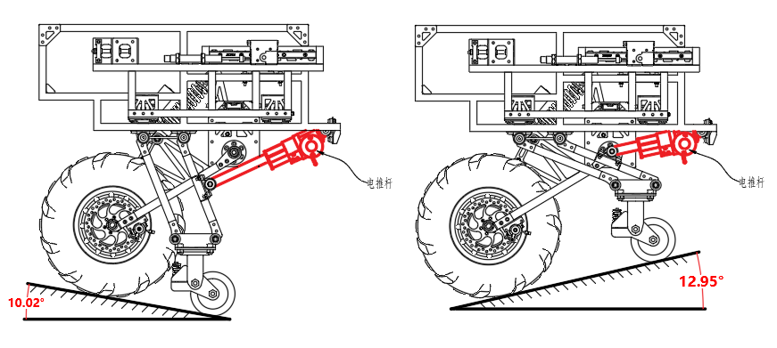
Figure 15. Effectiveness of adjusting ground clearance
The motion diagram of the rear wheel lift mechanism is shown in Figure 16. The small wheels, along with linkages 1, 2, and 3, form a parallelogram structure. Push rod 4 and groove 5 of the electric push rod act on the midpoint C of linkage 3, driving the small wheels to rotate around point A in vertical motion.
Since the rear wheels are equipped with universal wheels, to ensure that the universal wheels rotate perpendicular to the vehicle body when the ground clearance adjustment mechanism moves to any position, the linkages 1, 2, and 3 are designed as parallelogram linkages.
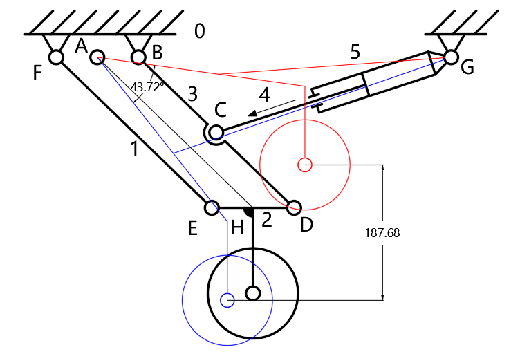
Figure 16. Motion diagram of rear wheel lift mechanism
Next, we verify the operational capacity of the electric push rod. The force situation on the variable ground clearance mechanism on a flat surface is shown in Figure 17. The resultant forces at each hinge point are denoted as \( {F_{a}},{F_{b}}{,F_{c}}{,F_{d}}{,F_{e}},{F_{f}} \) , with the thrust of the electric push rod represented by \( {F_{t}} \) , and the ground support force by \( {F_{N}} \) .
Linkage 1 (AE) and electric push rod 5 (CF) form a two-force member, hence:
\( {F_{a}}={F_{e}} \)
\( {F_{c}}={F_{f}}={F_{t}} \) (10)
Assuming the harvester’s weight distribution is uniform and the load on the three tires is equal, then:
\( {F_{N}}=\frac{G}{3} \) (11)
For component 2 (ED), the equilibrium equations are:
\( {F_{ⅆx}}-{F_{e}}cosα=0 \)
\( {F_{e}}sinα+{F_{ⅆy}}+{F_{N}}=0 \)
\( \frac{1}{2}{L_{ED}}({F_{e}}sinα-{F_{ⅆy}})=0 \) (12)
Where:
\( {L_{ED}} \) : Length of link ED
\( {F_{ⅆx}}{/F_{ⅆy}} \) : Component of force \( {F_{d}} \) along the x-axis/y-axis
\( {F_{ex}}{/F_{ey}} \) : Component of force \( {F_{e}} \) along the x-axis/y-axis
For linkage 3 (BD), the equilibrium equations are:
\( {F_{bx}}+{F_{ⅆx}}-{F_{c}}cos{β}=0 \)
\( {F_{by}}+{F_{ⅆy}}-{F_{c}}sin{β}=0 \)
\( {F_{c}}{L_{BC}}cosβsin{α}-{F_{ⅆx}}{L_{BD}}sin{α}+{F_{c}}{L_{BC}}sinβcos{α}-{F_{ⅆy}}{L_{BD}}cos{α}=0 \) (13)
where:
\( {L_{BC}} \) - Length of linkage BC
\( {L_{BD}} \) - Length of linkage BD
\( {F_{bx}}{/F_{by}} \) : Component of force \( {F_{b}} \) along the x-axis/y-axis
\( {F_{ⅆx}}{/F_{ⅆy}} \) : Component of force \( {F_{d}} \) along the x-axis/y-axis
For the entire system, the equilibrium equations are:
\( {F_{a}}cos{α}+{F_{bx}}-{F_{f}}cos{β}=0 \)
\( {F_{by}}+{F_{N}}-{F_{a}}sin{α}-{F_{f}}sin{β}=0 \)
\( {F_{f}}sin{β{L_{BF}}}-{F_{a}}sin{α{L_{AB}}}-{F_{N}}{L_{B{H^{ \prime }}}}=0 \) (14)
where:
\( {L_{BF}} \) : Length of link BF
\( {L_{B{H^{ \prime }}}} \) : Length of \( {BH^{ \prime }} \) , where \( {H^{ \prime }} \) is the intersection of the perpendicular from point H to BF
\( {F_{bx}}{/F_{by}} \) : Component of force \( {F_{b}} \) along the x-axis/y-axis
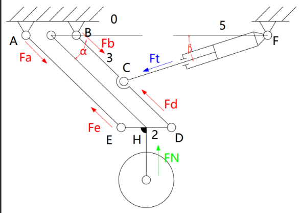
Figure 17. Force analysis diagram of the electric push rod
Here:
\( G=mg=70×9.8=686N \)
\( {L_{ED}}=114mm \)
\( {L_{BC}}=151mm \)
\( {L_{BD}}=300mm \)
\( {L_{BF}}=401mm \)
\( α=13.8°~60.7° \)
\( β=12.4°~25° \)
\( {L_{B{H^{ \prime }}}}=33mm~213mm \)
From equation (11):
\( {F_{N}}=228.7N \)
By combining equations (10), (11), (12), (13), and (14), we write a Matlab program to solve the equilibrium equations. According to Matlab calculations, when \( α=13.8° \) and \( β=25° \) , the maximum required thrust for the electric push rod is determined, with a maximum value of \( {F_{tmax}}={F_{cmax}}=704.2N \lt 1000N \) . Thus, the ground clearance adjustment mechanism operates effectively.
3.3. Design of harvester mechanism
Due to the varied terrain in the Qinghai-Tibet Plateau region, conventional harvesters often encounter blind spots in harvesting crops on hilly terrains, and the harvester’s structure rigidly attached to the chassis can hinder its passage through complex terrains. Therefore, to ensure smooth harvesting under different conditions, we have designed this 3-degree-of-freedom harvester mechanism, as shown in Figure 18. The three-degree-of-freedom harvester mechanism consists of mechanical arms, electric push rods, cutting blades, threshing chains, threshing wheels, crop dividers, welding frames, and other components [7].
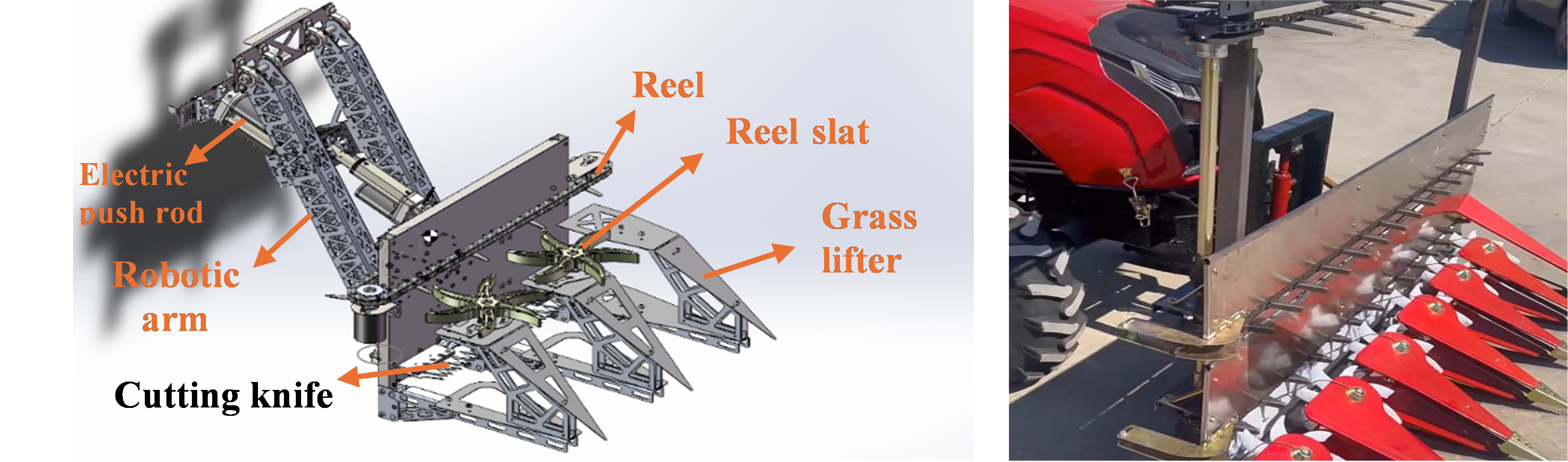
Figure 18. Schematic of the 3-Degree-of-Freedom Harvester Mechanism and Comparison with Conventional Harvester Harvesting Structure
3.3.1. Working principle of the harvester mechanism
3.3.1.1. Working principle of the 3-degree-of-freedom mechanical arm
The three-degree-of-freedom mechanical arm consists of a frame, linkage component 1 (AE), linkage component 2 (FE), electric push rod 1, electric push rod 2, and a rotating mechanism. Its operational diagram is shown in Figure 19.
When electric push rod 1 extends or contracts, the length of BC changes, causing linkage component 1 to swing around hinge point A, with a maximum swing angle of 14.18°. Similarly, when electric push rod 2 extends or contracts, the length of DF changes, causing linkage component 2 to swing around hinge point E, with a maximum swing angle of 19.88°. By appropriately controlling the extension of these two electric push rods, the harvester mechanism can be accurately controlled for lifting and lowering operations. When working on sloped farmland, this mechanism enables the harvesting device to adapt actively to the slope, ensuring smooth harvesting of crops planted on hillsides.
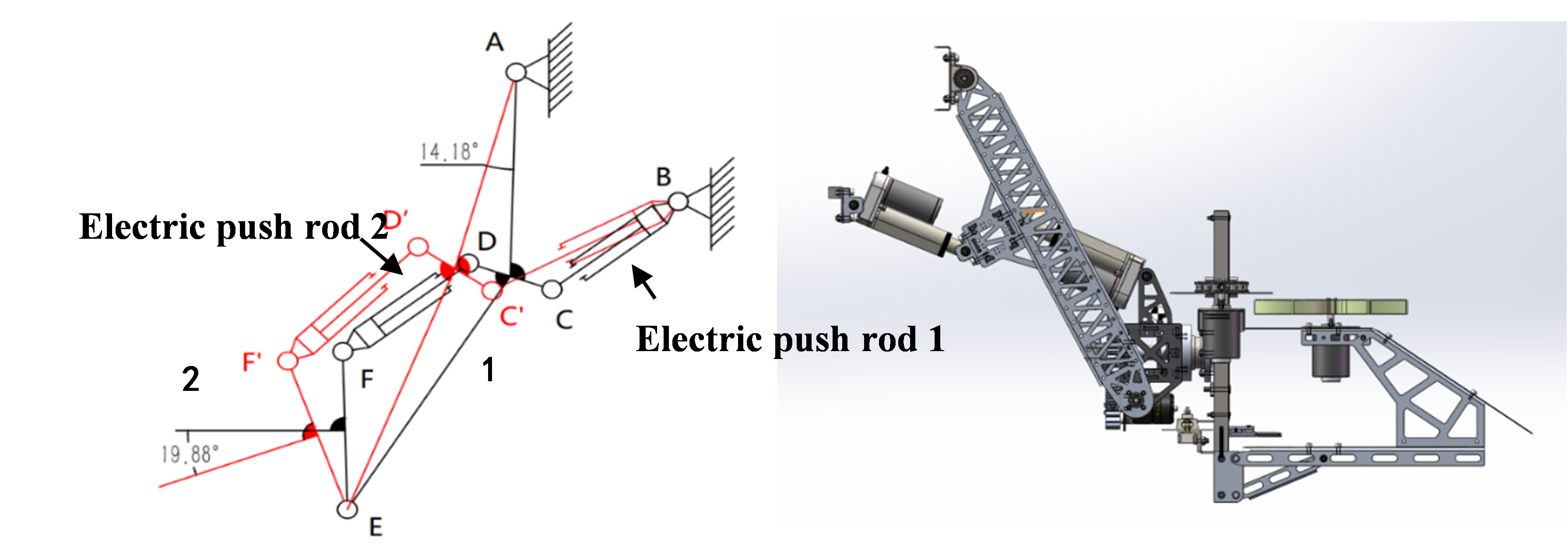
Figure 19. Operational Diagram and Schematic of the 3-Degree-of-Freedom Mechanical Arm
The rotating mechanism is located at the center of linkage component 2, with its structural diagram shown in Figure 20. It consists of a motor, small gear 1, large gear 2, and a main shaft. The motor drives the rotation of small gear 1, which meshes with large gear 2, thereby rotating the large gear. The large gear 2 is connected to the harvesting device via the main shaft. Ultimately, the rotational motion of the motor is transmitted to the harvesting device, enabling it to rotate around the axis. The final movement effect of the rotating mechanism is depicted in Figure 25. When harvesting crops on sloping terrain horizontally, the rotating mechanism allows the harvesting device to rotate within the plane at an angle corresponding to the slope, enhancing the efficiency of the harvester.
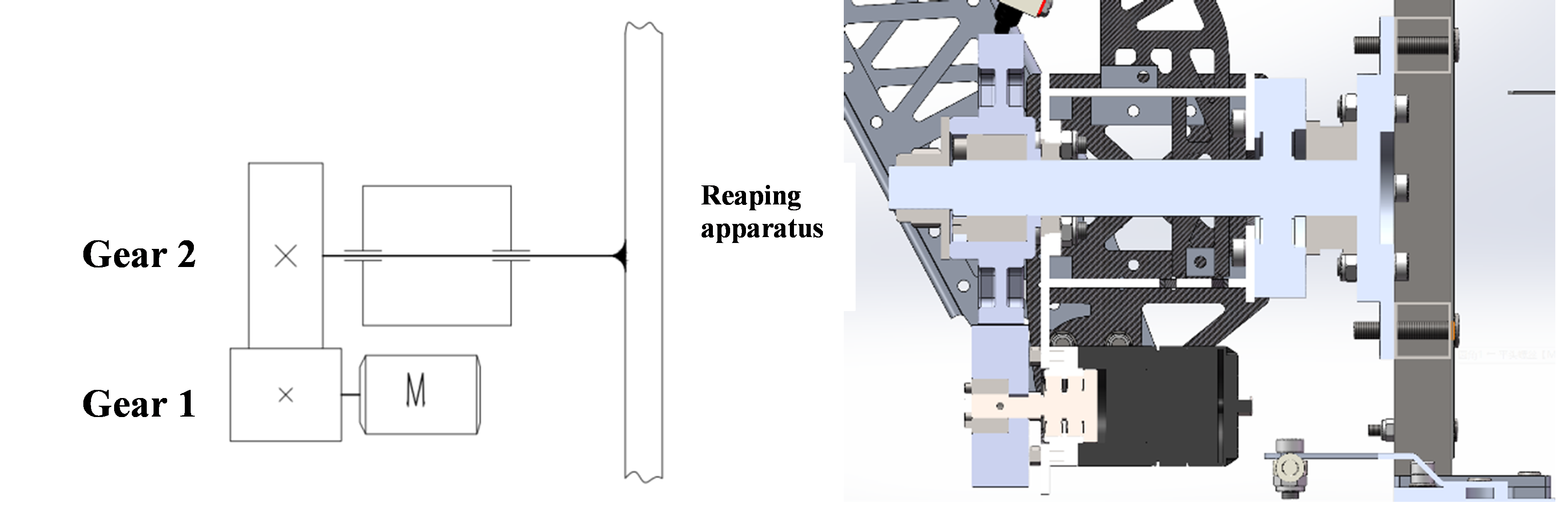
Figure 20. Structural Diagram and Schematic of the Rotating Mechanism
Due to the significant rotational inertia of the harvesting device at the front end of the rotating mechanism, the motor experiences a heavy load during operation. Therefore, to reduce the motor load, in addition to using a single-stage gear to increase torque, we designed the center of mass to be located at the central main shaft position, thereby reducing the rotational inertia of the harvesting device.
3.3.1.2. Working principle of the harvesting device
The harvesting device is composed of a welding frame, crop dividers, threshing wheels, cutting blades, threshing chains, and driving motors [8], as shown in Figure 21. During barley harvesting operations, the triangular crop dividers at the front will align and separate the incoming barley, directing them into the harvesting device through different entrances. Subsequently, the rotating threshing wheels driven by independent motors push the incoming barley towards the cutting blades. The cutting blades consist of a crank-slider mechanism driven by a reduction motor, upper blade, lower blade, and slide groove, as illustrated in Figure 21. The reduction motor’s rotation drives the crank-slider mechanism in a reciprocating linear motion. The upper blade, connected to the output end of the crank-slider mechanism via a triangular sheet metal, moves back and forth within the slide groove. The lower blade is fixed to the frame, resulting in relative movement between the upper and lower blades, thereby cutting the barley stems pushed by the threshing wheels.
The threshing chain moves under the drive of an independent motor, and the threshing paddles mounted on it continuously push the cut barley towards the side of the harvesting device under the combined action of the threshing wheels, completing the entire harvesting process.
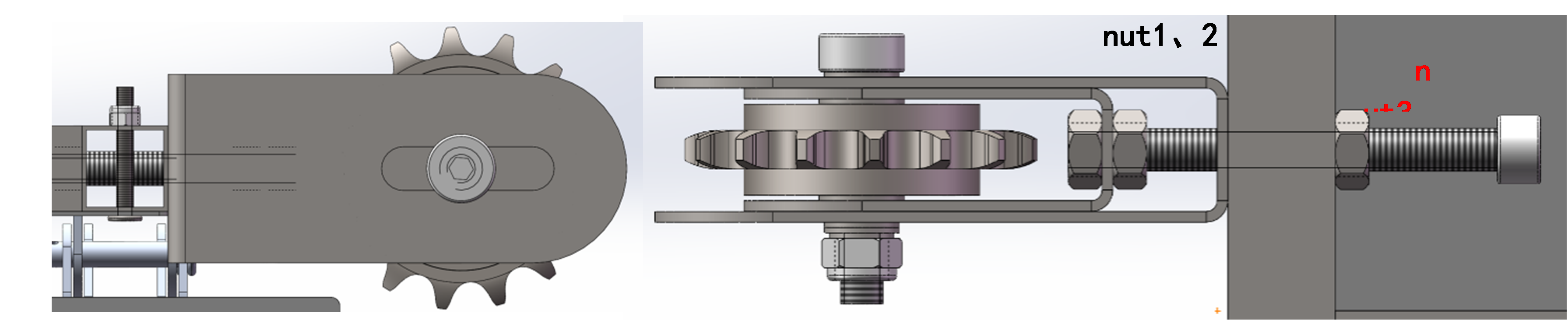
Figure 21. Schematic of the cutting blades
3.3.2. Design of key components of the harvesting mechanism
To achieve a lightweight design without compromising structural strength under high-strength conditions, our team proposed the following solutions:
(1) Selection of Lightweight Materials
While ensuring structural strength requirements are met, we chose materials with lower density whenever possible.
(2) Removal of Non-Essential Material from Parts
Using Ansys, we conducted stress simulations on designed parts and removed materials from sections with minimal stress according to simulation results.
(3) Use of Special Installation Methods
To enhance overall structural strength without increasing weight, we employed mortise and tenon joints on plate components. This method combines bolt loading with mortise and tenon loading, effectively strengthening the structure.
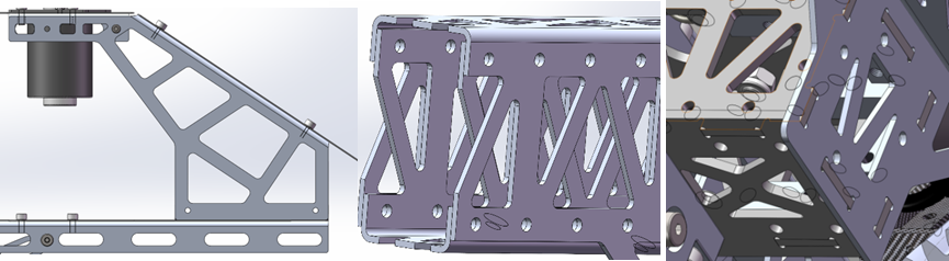
Figure 22. Schematic of removal of non-essential materials, C-shaped sheet metal, and mortise and tenon structure
For the convenient installation and maintenance of the threshing chain, we designed a simple adjustable chain tensioning device, as illustrated in Figure 23. This device consists of nuts 1, 2, and 3, bolts, outer sheet metal, and inner sheet metal, forming a simple screw mechanism. By rotating the bolt, the sprockets can be moved left and right within the groove, adjusting the distance between the two sprockets to tension the chain.
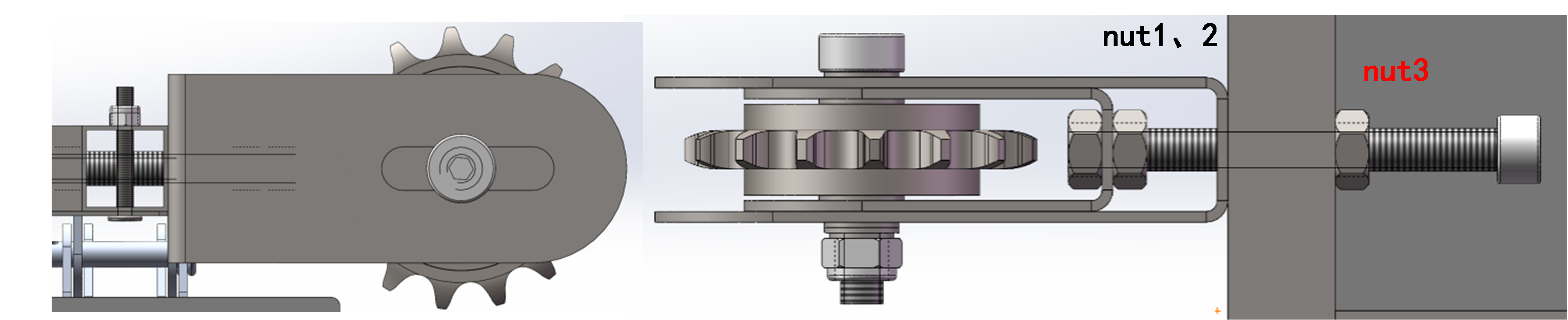
Figure 23. Schematic diagram of sprocket tensioning device structure
3.4. Design of shelf scheme
To enhance the functionality of the harvester, we designed an optional shelf for the harvester, as shown in Figure 24.
This shelf (Figure 11) is primarily composed of sheet metal and thin steel pipes. Three long sheet metals are hinged at both ends to side panel sheet metals using hinges, and four \( 10mm×10mm \) thin steel pipes are inserted into square holes in the side panel sheet metals. Once the positions of the three long sheet metals are determined, they are fixed by welding using argon arc welding. The ends of the sheet metal pieces are designed with protruding small platforms to support the side panels horizontally. Stainless steel wind hooks are installed at the four corners of the shelf to keep the side panels upright. Multiple slots are provided on both long and short sheet metal pieces for users to pass ropes to tie up goods. Additionally, small holes are available for installing slots and other components to store agricultural tools and equipment.
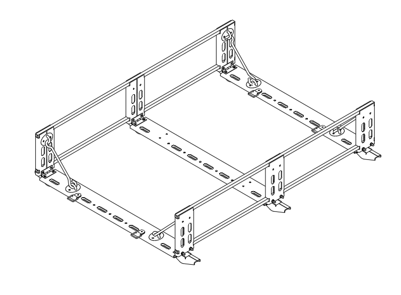
Figure 24. Structural diagram of the shelf
4. Key component verification and optimization design
The high-altitude mountain barley harvester is an integrated system based on mechanical structures, incorporating electrical control. To optimize the structural design and enhance functionalities such as road driving and field operations, the focus is on the optimization and verification of key components. Based on the studies in the preceding chapters, this paper mainly verifies and optimizes the following critical components of the harvester:
(1) Side Wheel-leg Mechanism
(2) Central Frame
(3) Sliders on Both Sides of the Central Linkage Mechanism
(4) Transmission Gears of the 3-DOF Harvesting Arm
4.1. Foundation for auxiliary optimization design
To ensure the optimized structure meets operational requirements, after formulating preliminary optimization plans, three-dimensional models are constructed using SolidWorks software based on design specifications and basic dimensions. These models are then imported into Ansys Workbench for finite element analysis (FEA), including static structural and modal analyses.
The optimization analysis focuses on existing product issues, analyzing and adjusting structures for optimization. Through FEA calculations, local reinforcement of structures is conducted to verify structural reliability [4, 8].
4.2. Analysis and calculation of side wheel-leg mechanism
4.2.1. Calculation of linkage dimensions for wheel-leg mechanism
The diagram in Figure 25 illustrates the pressure angles of various linkages in the wheel-leg mechanism structure. The CD rod is a selected hydraulic damping spring with a length of 220mm, while the DE rod is a selected fisheye bearing rod with a length of 150mm. The large wheel is an 8-inch off-road wheel with an approximate outer diameter of 400mm. The height of the vehicle body from the ground needs to be around 600mm. The fixed hinge B distance from the upper plane is 200mm.
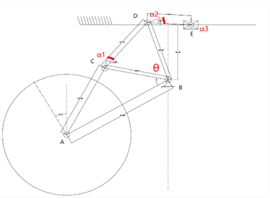
Figure 25. Schematic of Pressure Angles of Various Linkages in the Wheel-leg Structure
To ensure proper transmission of the low-speed linkage mechanism and optimal stress distribution among its components, the pressure angle α must satisfy \( α \lt 5{0^{∘}} \) . To further guarantee correct operation, each angle α is planned to be less than \( 3{0^{°}} \) . Initially, arcs of 60 degrees are drawn with point E as the center at both extremes of slider E’s travel, using a radius of 150 mm along DE, symmetrically about the horizontal line. A circle is then drawn with point B as the center and DB as the radius. The intersection points of these circles with the arcs define the required length of rod DB. Additionally, the length of hydraulic damping spring CD, which is 220 mm, and the rods CB and BC, must all satisfy a maximum pressure angle of less than \( 3{0^{°}} \) . Since BC, CD, and BD form a triangle, the property of triangles dictates that as the spring CD compresses and shortens, its adjacent angles increase. Hence, the initial state pressure angle becomes the maximum pressure angle. Therefore, the angles α for CD relative to BD and CB relative to CD must all be \( ≤3{0^{°}} \) . Considering the pressure angle for BD relative to DE, as well as factors such as mechanism size and ease of fabrication, the lengths of BD and BC are chosen to be 220 mm.
Rods AB, BC, and AC collectively form a component, with rod AB inclined at an angle of \( 3{0^{°}} \) to the horizontal plane. Thus, the lengths of AB and AC can be freely chosen based on expected vehicle dimensions, vehicle height, equivalent stress levels, and ease of fabrication. It is determined that the length of AB is 400 mm, and the length of AC is 275 mm.
4.2.2. Verification of transmission angle and pressure angle in the wheel-leg mechanism
When the harvester’s two wheels are not in contact with the ground and slider E can freely slide, let the rotation angle of the wheel-leg mechanism be \( θ \) . Assuming the ideal length of spring CD remains unchanged, hence \( {α_{1}} \) and \( {α_{2}} \) remain constant. The pressure angle \( {α_{3}} \) between linkage DE and slider E varies with \( θ \) . The relationship can be computed as follows:
\( {α_{3}}=arccos{(}\frac{({L_{BD}}sin{(}θ)-200)}{{L_{DE}}}) \) (15)
This equation is input into Matlab to plot the curve showing its variation, as depicted in Figure 26.
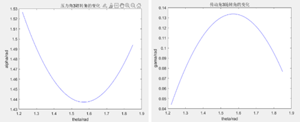
Figure 26. Variation of Pressure Angle (left) and Transmission Angle (right) of Linkage DE with Slider E as \( θ \) changes
When both sides of the harvester’s wheels are in contact with the ground and slider E’s movement is constrained, let the rotation angle of the wheel-leg mechanism be \( θ \) . Since \( {L_{BC}}={L_{BD}}=220mm \) , the pressure angle \( {α_{1}} \) of linkage BC on the spring and the pressure angle \( {α_{2}} \) of the spring on linkage BD satisfy \( {α_{1}}={α_{2}} \) . Assuming the compression amount of the spring is x, then \( {L_{CD}}=220-x \) . Based on geometric relationships, the angles α₁ and α₂ are calculated as:
\( {α_{1}}={α_{2}}=arccos{(}\frac{{L_{CD}}}{2{L_{CB}}})=arccos{(}\frac{{L_{CD}}}{2{L_{BD}}}) \) (16)
The variation of these angles over time is plotted as shown in Figures 27 and 28.
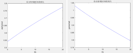
Figure 27. Variation of Pressure Angle and Transmission Angle of Linkage BC on the Spring over Time
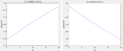
Figure 28. Variation of Pressure Angle and Transmission Angle of Spring on Linkage BD over Time
4.2.3. Dynamics analysis of wheel-leg mechanism
At a certain moment, let the wheel-leg rotate around point B with angular velocity \( {ω_{1}} \) and angular acceleration \( {α_{1}} \) . In the ideal scenario, where the slider moves without friction and the spring undergoes no deformation, the analysis here focuses solely on the dynamic statics of the slider's motion when unrestricted.
Under the assumption, the component ABCD experiences angular acceleration \( {α_{1}} \) . Due to the special shape of this component and the uneven distribution of mass, for simplicity, we neglect the smaller mass parts and concentrate the mass of the wheel system at the axle of the rubber wheel. Let the mass of the wheel system be \( {m_{1}} \) =5kg, and the rotational inertia be \( {J_{1}}={m_{1}}{r^{2}}=8×1{0^{5}}kg.m{m^{2}} \) . The inertial force \( {F_{1}}=0 \) and the inertial moment \( {M_{1}}={J_{1}}{α_{1}} \) .
Rod DE undergoes both translational and rotational motion. Observing the relationship between components, since the angular velocity of slider E is 0, the acceleration of rod DE relative to the ground equals the angular velocity relative to the slider. The angular displacement \( {θ_{2}} \) is calculated as:
\( {θ_{2}}=arccos(\frac{{L_{BD}}sin{{θ_{1}}}-200}{150}) \) (17)
The angular velocity \( {ω_{2}} \) of θ_2 with respect to time is the first derivative \( {ω_{2}}=\frac{ⅆ{θ_{2}}}{ⅆt} \) . The angular acceleration \( {α_{2}} \) is the first derivative of angular velocity \( {ω_{2}} \) with respect to time \( {α_{2}}=\frac{ⅆ{ω_{2}}}{ⅆt} \) .
The translational velocity at point D in the horizontal direction component is:
\( {v_{2}}={ω_{1}}{L_{DB}}cos{{θ_{1}}} \) (18)
The acceleration \( {a_{2}} \) is defined as the first derivative of \( {v_{2}} \) with respect to time: \( {a_{2}}=\frac{ⅆ{v_{2}}}{ⅆt} \) . The rod DE is a rod with a spherical bearing, and its mass is approximately \( {m_{2}}=0.3kg \) . The moment of inertia is given by \( {J_{2}}=\frac{1}{3}{m_{2}}{{L_{BD}}^{2}} \) . From this, we can determine the inertial force \( {F_{2}}={m_{2}}{a_{2}} \) , and the inertial moment \( {M_{2}}={J_{2}}{α_{2}} \) .
Using the above calculations, the results are compiled into a program input for Matlab to simulate and plot, yielding results as shown in Figure 29.
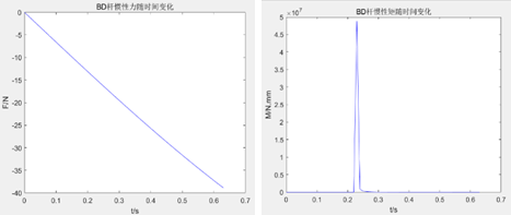
Figure 29. Inertial Force (left) and Inertial Moment (right) of Component ABCD over Time
4.2.4. Finite element analysis of key components in the wheel-leg mechanism
The main shaft of the wheel-leg, a critical component of the harvester, directly impacts the performance and lifespan of the harvester. The main shaft of the wheel-leg is depicted in Figure 30.

Figure 30. Main Shaft of the Wheel-leg Mechanism
The main shaft material is 303 stainless steel, an austenitic stainless steel known for its easy machinability and high surface finish requirements, containing sulfur and selenium. Its mechanical properties are as follows: tensile strength \( {δ_{b}} (MPa) \) ≥ 520 MPa, yield strength at 0.2% offset \( {δ_{0.2}}(MPa) \) ≥ 205 MPa, elongation \( {δ_{5}}(\%) \) ≥ 40%, reduction of area \( ψ(\%) \) ≥ 50%, hardness HB ≤ 187 HB, HRC ≤ 90, HV ≤ 200 HV. These mechanical performance parameters were input into the material database of the analysis software to define the material used in the model.
A static load finite element analysis was conducted on the main shaft of the wheel-leg. Assuming the harvester’s total weight is 80 kg and each rubber wheel receives a support force of \( \frac{G}{2} \) from the ground, based on force analysis of the wheel-leg mechanism, the main shaft also experiences a force of \( \frac{G}{2} \) in the vertical direction. Therefore, a force of 400 N was applied to the main shaft in Ansys, constraints were applied, and the solution was obtained. The results are shown in Figure 31.
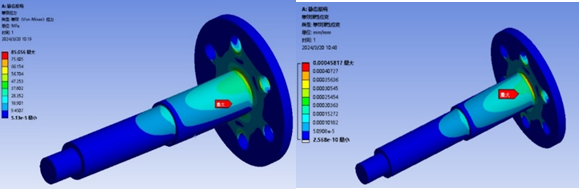
Figure 31. Equivalent Stress (left) and Equivalent Strain (right) of Main Shaft under Static Load Simulation
According to the simulation results, under the action of a 400 N static load, the maximum equivalent stress on the wheel-leg main shaft is located at the root of the shaft corner, with a magnitude of \( 85MPa \) . This value is significantly less than the yield strength of the steel, \( 205MPa \) , indicating that the designed strength of the wheel-leg main shaft fully meets the design requirements. The maximum equivalent strain also occurs at the stress concentration point at the root of the shaft corner, with a maximum equivalent strain value of \( 4.58×{10^{-4}}mm \) .
A fatigue analysis was conducted on the wheel-leg main shaft under constant amplitude loading. A pulsating cyclic load with a maximum value of 800 N was applied, using a fatigue strength factor of 1 and a proportion factor of 2, based on the theory of average stress-life curve. The results are shown in Figure 32.
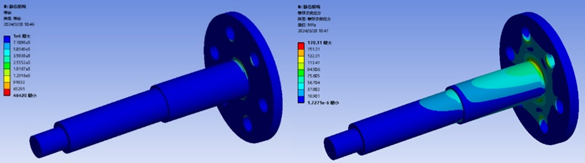
Figure 32. Fatigue Life (left) and Equivalent Alternating Stress (right) of Main Shaft under Fatigue Simulation
According to the simulation results under the above conditions, the majority of the wheel-leg main shaft can withstand over 700,000 cycles without failure. The maximum equivalent alternating stress is \( 170MPa \) , which is lower than the yield strength of the steel, \( 205MPa \) , demonstrating that it meets the operational requirements effectively.
4.3. Finite element analysis of central frame
To prevent resonance issues in the harvester chassis structure and enhance machine performance and longevity, it is crucial to calculate or simulate the vibration characteristics of the chassis structure. A three-dimensional model of the frame was selected for finite element analysis. A new case was established for modal and random vibration analyses. The material properties of the model were defined as 303 stainless steels. Boundary constraints were set at the weld points between the frame and the sliding track adapter sheet metal.
The frequency analysis results for the first five modes of the frame are as follows: 1st mode at 59.176 Hz, 2nd mode at 123.27 Hz, 3rd mode at 145.35 Hz, 4th mode at 149.43 Hz, and 5th mode at 187.92 Hz. Additional results are shown in Figure 33.
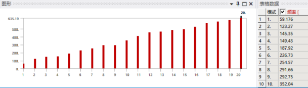
Figure 33. Modal Analysis Results up to 20th Mode of the Frame
Typically, lower mode vibration types have a more significant impact on the mechanical structure’s vibration. From the frequency analysis results, the lowest natural frequency of the frame is 59.176 Hz. Therefore, under normal circumstances, vibrations from the road surface are unlikely to cause resonance and damage to the frame.
4.4. Finite element analysis of sliders on both sides of the central linkage mechanism
The force analysis of the sliders on both sides of the central linkage mechanism is depicted in Figure 34. The rubber wheel shaft experiences a normal reaction force \( {F_{N}} \) from the ground, while the hinge point on the slider receives a spring force F from the fish-eye rod. For simplicity in calculation, vertical force components of F are neglected. The moment balance equation of the structure is listed as follows:
\( {F_{N}}{x_{1}}=F{x_{2}} \) (19)
where \( {x_{1}} \) is the distance from \( {F_{N}} \) to the pivot axis, approximately 346 mm, and \( {x_{2}} \) is the distance from \( F \) to the pivot axis, approximately 269 mm.
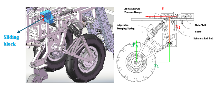
Figure 34. Force Analysis Diagram of the Slider
Assuming \( {F_{N}} \) = 400 N, from equation (19), \( F=514.5N \) is calculated. Static simulations of the sliders were performed in Ansys, where a load of 514.5 N was applied at the hinge, constraints were imposed, and solutions were obtained. The results are shown in Figure 35:
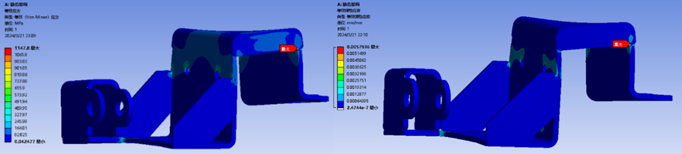
Figure 35. Equivalent Stress (left) and Equivalent Linear Strain (right) of Sliders under Static Load
The material used for the sheet metal of the sliders on both sides of the central linkage mechanism is 304 stainless steels. Its mechanical properties are as follows: tensile strength \( {σ_{b}} (MPa) ≥515 \) , yield strength \( {δ_{0.2}} (MPa) ≥205 \) , elongation \( {δ_{5\%}}≥40 \) , \) hardness ≤201HBW, ≤92HRB, ≤210HV, density at 20°C is 7.93 g/cm³, melting point is between 1398 to 1454°C, and longitudinal modulus of elasticity at 20°C is 193 KN/mm². From the simulation results, it is observed that under the prescribed load, the maximum equivalent stress on the sliders of the central linkage mechanism reaches \( 1147.8MPa \) , and the maximum linear equivalent strain is \( 0.0058mm \) . For the simulation results of equivalent stress, the values are significantly higher than the yield strength of 304 stainless steel. Using probes, it was discovered that the maximum equivalent stress occurs at the sharp corners of the weld joints between the two steel plates, which are stress concentration points. However, in actuality, these weld joints are adequately filled with welding material, eliminating the sharp corner conditions present in the simulation model. Additionally, probing other parts of the component shows that the equivalent stresses are all below \( 164MPa \) , which is less than the yield strength condition \( {δ_{0.2}}=205MPa \) for 304 stainless steels, thereby meeting the normal operational requirements of the part.
Below is the simulation calculation of fatigue strength for the central linkage mechanism's two-side sliders. A maximum cyclic load of 514.5N is applied, using a fatigue strength factor of 1 and a proportionality factor of 2, based on the theory of mean stress correction. The results obtained are shown in Figure 36.
The results indicate that under the specified conditions, excluding stress singularities, the sliders can withstand more than \( {1.4×10^{5}} \) cycles without damage. Moreover, the equivalent alternating stresses are all below \( 262MPa \) , demonstrating that they meet the usage requirements effectively.
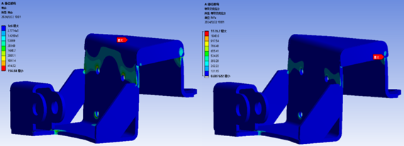
Figure 36. Fatigue Simulation Life of Sliders (Left) and Equivalent Alternating Stress (Right)
4.5. Finite element analysis of three-degree-of-freedom harvester arm transmission gears
According to the drawings, the distance from the center of the harvesting device to the spindle is approximately 20 mm, with a mass of about 6.5 kg. Its moment of inertia is calculated as \( J={J_{0}}+m{R^{2}}=2600kg·{mm^{2}} \) . Assuming an angular acceleration \( α=0.1rad/{s^{2}} \) , the resulting moment of inertia \( T=αJ=260N·mm \) . The gear material is nylon reinforced with fibers, characterized by a tensile strength of \( 44MPa \) , tensile modulus of \( 3500MPa \) , elongation at break of \( 5\% \) , flexural strength of \( 65MPa \) , flexural modulus of \( 2400MPa \) , notch impact strength of \( 4.31KJ/{m^{2}} \) , and unnotched impact strength of \( 19.28KJ/{m^{2}} \) .
Applying the angular acceleration \( α=0.1rad/{s^{2}} \) to the driving gear (small gear) and the torque \( T=260N·mm \) to the driven gear (large gear), with appropriate boundary conditions imposed, simulations were conducted. The simulation results are shown in Figure 37.
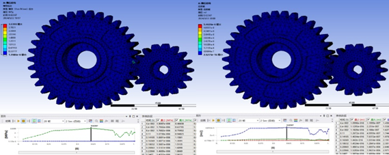
Figure 37. Equivalent Stress (left) and Strain Energy (right) of Transmission Gears under Instantaneous Impact
From the simulation results, it is observed that the maximum equivalent stress on the transmission gears is approximately \( 3MPa \) , and the maximum strain energy is about \( 5.46KJ \) , both of which meet the material’s usage conditions. Therefore, the transmission gears of the harvester mechanism can operate effectively under these conditions.
5. Control scheme design
5.1. Circuit overall design
The circuit system is powered by a 6s lithium battery:
(1) The lithium battery pack provides high-power input of over a kilowatt to the power system, with minimal output fluctuations.
(2) For the control system, a self-made step-down module supplies 5V, integrating input reverse protection, over-voltage protection, and output filtering.
(3) Power system control is achieved via bus communication, ensuring a simple and stable circuit design.
5.2. Hardware design
5.2.1. Self-made step-down module introduction
The module employs a DC-DC step-down circuit. After comparing XL2506, SY8303, and TPS54540DDAR chips, SY8303 was chosen as the main control module due to:
(1) Over-voltage protection, reverse protection, and over-current protection.
(2) High switching frequency and low output ripple.
5.2.2. Self-made main control board module introduction
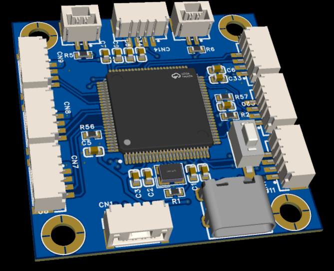

Figure 38. Model and Physical Image of Self-made Main Control Module
Based on the STM32F407VGT6 chip, the self-developed development board features:
(1) Operates at a high main frequency of 168 MHz.
(2) Multiple USART communication ports, capable of connecting to various complex peripherals.
(3) Integrated CAN communication chip.
(4) Integrated USB-to-TTL, enabling direct communication with a host computer via a Type-C interface.
(5) Compact size of 40*40 mm.
The module utilizes the EG2104 chip as the control unit, with IRF3607 high-power MOSFETs for motor drive, ensuring high linearity, voltage tolerance, and power capability.
5.3. Software architecture
(1) Runs on the FreeRTOS system on the self-made STM32F407 control board, structured into FreeRTOS system layer, driver layer, device layer, and application layer.
(2) Decouples the driver layer from the application layer, facilitating quick porting when changing similar platforms.
(3) Completes low-level driver encapsulation, simplifying development processes.
(4) Utilizes the FreeRTOS operating system for efficient multitasking handling.
(5) Shares vehicle status data across tasks, simplifying data storage and management.
6. Results and discussion
Based on the actual conditions and requirements of Tibetan areas, the high-altitude barley harvester designed in this paper primarily features the following innovations:
(1) Flexible harvesting mechanism.
(2) Linkage suspension mechanism.
(3) Adjustable pitch angle design of the vehicle body.
(4) Variable track mechanism.
(5) Multi-functional shelf.
(6) Adjustable armrest.
(7) Hub motors driven by electric vehicle brushless controllers, ensuring high-power stability and reliability.
(8) Utilizes STM32 for CAN communication throughout the vehicle, providing stable, reliable, high-frequency, and anti-interference communication.
(9) Control system includes hardware and software-based brake and power cut-off features, ensuring safety and reliability.
(10) Offers Bluetooth control, handle control, and 2.4G wireless communication, catering to various complex control needs.
(11) All control system circuit boards are self-designed, with component selection based on market demand and cost-effectiveness.
(12) Code development adopts the FreeRTOS system, organized into tasks for easy maintenance and addition of new features.
Additionally, practical prototype vehicles were produced, tested, and subsequently upgraded based on test results.
7. Summary and outlook
This paper addresses the current lack of suitable high-altitude barley harvesting machinery for the Tibetan agricultural market in China. Based on the structure of traditional handheld reapers and driers, and considering the terrain and agronomic needs of regions like Western Sichuan and Qinghai-Tibet Plateau, extensive domestic and international literature was reviewed. This study further investigates and analyzes existing models, identifying their shortcomings, and proposes structural optimizations tailored to the small village landscapes and agricultural conditions of Tibetan regions, thereby developing an advanced, efficient, and intelligent barley reaping and drying machine.
Key conclusions drawn from the research are as follows:
(1) Optimized the overall design scheme of the harvester based on operational requirements, agricultural techniques, and economic factors specific to the operating regions.
(2) Analyzed and iteratively optimized the overall structure of the harvester to enhance stability and performance.
(3) Established dynamic characteristics analysis models for the harvester, evaluating the dynamic properties of each component, including pressure angle, transmission angle, acceleration, and angular acceleration.
(4) Conducted static and fatigue analyses on critical components, modal analysis on the chassis, and transient structural analysis on the gear system, confirming that strength and durability meet operational requirements. Vibration under normal use conditions does not damage the vehicle body, nor does it cause failures due to momentary impacts.
However, new challenges have emerged that require further improvement:
(1) The variable track mechanism experiences complex and substantial forces, significantly affecting the overall structural stiffness. Some parts of the harvester deform considerably during operation, necessitating further structural improvements to enhance reliability.
(2) Significant errors during machining and assembly processes have reduced mechanical reliability.
(3) Interchanging different components of the harvester is cumbersome and time-consuming, with poor interface compatibility. Designing more compatible quick-connect interfaces can enhance the harvester’s versatility.
(4) Optimizing the chassis weight to reduce overall vehicle weight is feasible.
References
[1]. LaBa, D. Z. (2021). Current situation and existing problems of mechanized harvesting of barley. Chinese Science and Technology Journals Database (Full-text version) Natural Science, 2021(10), 345-346.
[2]. Si, Z. B., & Yisima. (2023). Characteristics and development trend of whole process mechanized production of Tibet Hordeum vulgare var. coeleste Linnaeus. Agricultural Technology and Equipment, 2023(2), 91-93.
[3]. Li, X. (2023). Analysis of intelligent agricultural machinery manufacturing and development in hilly areas of China. In Shandong Yishui County Agricultural and Rural Bureau (Ed.), Proceedings of the Conference on Agricultural and Rural Development (pp. 79-86). ISBN: 100
[4]. Hu, Z. Y. (2018). Optimization design and experimental research on chassis structure of variable ground bed plant protection machine (Doctoral dissertation). Hunan Agricultural University.
[5]. Zhang, Z. Y. (2020). Structural design and research of semi-active suspension of inspection robot of belt conveyor (Master’s thesis). Anhui University of Science and Technology.
[6]. Slawsan, J. (2015). System and method of adjusting the chassis height of a machine. US Patent No. 20150102569.
[7]. Gao, M. Y. (2017). Study on the agricultural machinery of powered chassis and body leveling device of hilly mountainous (Doctoral dissertation). Jilin Agricultural University.
[8]. Zhang, S. L. (2020). Design and experiment of the baler for combine harvester of highland barley (Master’s thesis). Gansu Agricultural University.
Cite this article
Xie,R. (2024). Design and research on structure of plateau hand-held cutting and sun drying machine. Advances in Engineering Innovation,8,31-52.
Data availability
The datasets used and/or analyzed during the current study will be available from the authors upon reasonable request.
Disclaimer/Publisher's Note
The statements, opinions and data contained in all publications are solely those of the individual author(s) and contributor(s) and not of EWA Publishing and/or the editor(s). EWA Publishing and/or the editor(s) disclaim responsibility for any injury to people or property resulting from any ideas, methods, instructions or products referred to in the content.
About volume
Journal:Advances in Engineering Innovation
© 2024 by the author(s). Licensee EWA Publishing, Oxford, UK. This article is an open access article distributed under the terms and
conditions of the Creative Commons Attribution (CC BY) license. Authors who
publish this series agree to the following terms:
1. Authors retain copyright and grant the series right of first publication with the work simultaneously licensed under a Creative Commons
Attribution License that allows others to share the work with an acknowledgment of the work's authorship and initial publication in this
series.
2. Authors are able to enter into separate, additional contractual arrangements for the non-exclusive distribution of the series's published
version of the work (e.g., post it to an institutional repository or publish it in a book), with an acknowledgment of its initial
publication in this series.
3. Authors are permitted and encouraged to post their work online (e.g., in institutional repositories or on their website) prior to and
during the submission process, as it can lead to productive exchanges, as well as earlier and greater citation of published work (See
Open access policy for details).
References
[1]. LaBa, D. Z. (2021). Current situation and existing problems of mechanized harvesting of barley. Chinese Science and Technology Journals Database (Full-text version) Natural Science, 2021(10), 345-346.
[2]. Si, Z. B., & Yisima. (2023). Characteristics and development trend of whole process mechanized production of Tibet Hordeum vulgare var. coeleste Linnaeus. Agricultural Technology and Equipment, 2023(2), 91-93.
[3]. Li, X. (2023). Analysis of intelligent agricultural machinery manufacturing and development in hilly areas of China. In Shandong Yishui County Agricultural and Rural Bureau (Ed.), Proceedings of the Conference on Agricultural and Rural Development (pp. 79-86). ISBN: 100
[4]. Hu, Z. Y. (2018). Optimization design and experimental research on chassis structure of variable ground bed plant protection machine (Doctoral dissertation). Hunan Agricultural University.
[5]. Zhang, Z. Y. (2020). Structural design and research of semi-active suspension of inspection robot of belt conveyor (Master’s thesis). Anhui University of Science and Technology.
[6]. Slawsan, J. (2015). System and method of adjusting the chassis height of a machine. US Patent No. 20150102569.
[7]. Gao, M. Y. (2017). Study on the agricultural machinery of powered chassis and body leveling device of hilly mountainous (Doctoral dissertation). Jilin Agricultural University.
[8]. Zhang, S. L. (2020). Design and experiment of the baler for combine harvester of highland barley (Master’s thesis). Gansu Agricultural University.