


In China, the scarcity of available land resources in the southeastern region has become a major constraint on the development of photovoltaic (PV) power plants. Constructing solar PV power plants on water surfaces, thereby creating a floating PV power station in a fishery-solar complementary model, has emerged as an innovative solution[1].Compared to ground-based PV power stations, floating PV power stations have several advantages, including less land occupation, higher power generation efficiency, and improved water quality, thereby achieving comprehensive utilization of resources[2-3]. Currently, the key challenges and difficulties in designing floating PV power stations include: (1) floating platform design; (2) fixed connection design of the floating island; (3) vibration damping design between the floating island and the equipment; (4) layout design of the power station; and (5) cable routing and fire prevention. This paper takes a specific project as an example to deeply discuss and analyze these issues, demonstrating that the design is effective and has significant reference value based on practical engineering verification.
1.Comprehensive design scheme of the floating PV power station
1.1.Main electrical wiring
The project has an installed capacity of 40MWp, using a 1kV DC circuit. Each 8 DC circuits connect to a string inverter, with two inverters connecting to a combiner box, and 18 combiner boxes connecting to a transformer for stepping up voltage. Five transformers connect to a 35kV collection station through a collector line cabinet. The PV module's floating foundation adopts a structure of float tubes and brackets, secured by an anchoring system to adapt to water level changes within a 5m range.
The station employs a single-busbar system with four collector lines, one PT, two metering circuits, one SVG, one grounding transformer, an arc suppression coil set, and one outgoing line. The main wiring diagram is shown in Figure 1.
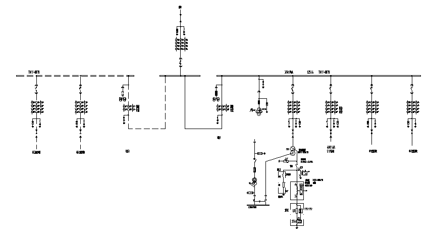
Figure 1. Main Wiring
The internal load voltage for the substation is 0.4kV, utilizing a directly grounded neutral point three-phase four-wire system. The station's power supply employs an integrated power source with a single busbar configuration and is fed by dual power sources. During construction, a feeder line from a nearby 10kV line is brought to an external construction transformer to serve as the construction power source. After construction is completed, the external construction transformer is retained to provide operational power for the substation. Additionally, a grounding transformer is used as a backup transformer to supply auxiliary power, with the backup power source derived from the 35kV busbar within the substation. The main and backup power sources are routed to an automatic transfer switch cabinet for the station's dual power supply system.
1.2.Electrical equipment layout
The switchgear station is placed on a floating platform, and the equipment is housed in prefabricated cabins, including 35kV switchgear cabins, secondary cabins, living cabins, SVG cabins, grounding transformer cabins, and arc suppression coil outdoor equipment. The layout of the electrical equipment is shown in Figure 2.

Figure 2. Electrical Equipment Layout Diagram
1.3.Lightning protection and grounding design
To ensure the safe operation of the power system and PV generation facilities, the switchgear station uses prefabricated cabin structures with lightning protection strips on the roofs. The cabins' metal framework serves as the down conductor. No independent lightning rods are set since there are no exposed outdoor equipment. Overvoltage protection is provided by installing lightning arresters in the 35kV distribution equipment and low-voltage cabinets.
The electrical equipment is placed on a steel floating platform. The steel platform serves as the main grounding grid, with copper cables extending to the water bottom as vertical grounding electrodes, ensuring a complete conductive path. Insulation resistance tests are conducted, and additional grounding electrodes are added if requirements are not met.
1.4.Electrical secondary system design
The project follows a "unattended" principle, with a computer monitoring system ensuring comprehensive control and monitoring. A comprehensive automation system is installed, providing protection, control, communication, and measurement functions for both the PV generation system and the 35kV switchgear station.
2.Design of the floating PV power station
The project comprises a floating island platform system, an anchoring system, and electrical switchgear. A modular steel support pontoon platform supports the modules, and prefabricated electrical equipment cabins are placed on the floating island, connected by prefabricated cables.
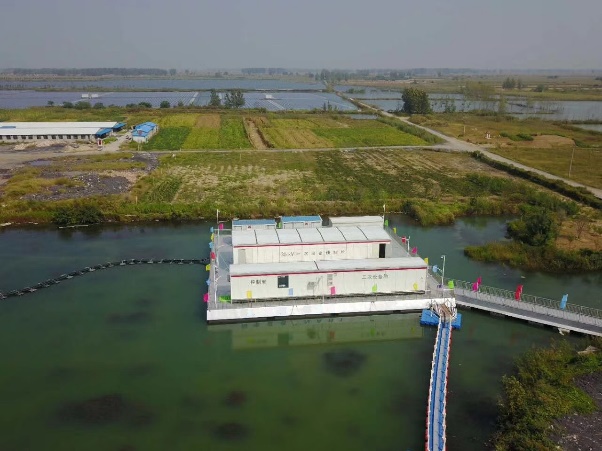
Figure 3. Completed Floating Switch Station on Water
2.1.Floating island platform design
2.1.1.Float device design
The design of the floating device follows the principle of maximizing surface area utilization, while also considering ease of installation and structural reliability of the connections. A cylindrical shape is chosen for the floating device. From the perspective of loss, the cylindrical shape can provide greater buoyancy with a smaller surface area. Regarding installation and fixation, due to the limitations of material usage and self-weight, the walls of the floating device are relatively thin, making the cylindrical shape easier to secure. From a stress perspective, the cylindrical shape distributes stress more evenly. In terms of floating stability, the cylindrical shape offers better stability compared to other shapes.
The safety design of the floating device adheres to the principle of non-sinking. Even in the case of defects in the anti-corrosion measures, the interior of the floating device still has waterproof mechanisms, allowing the platform to continue operating under normal load conditions. Therefore, the anti-corrosion and leak-proof design of the floating device is multi-layered. The outer layer is for anti-corrosion, the middle part is made of steel, and the interior is filled with hydrophobic materials. If the outer anti-corrosion coating is damaged, the steel part can still be used for 5-7 years. If the steel part is damaged, water may enter the floating device, but the hydrophobic materials inside will limit the amount of water entering, preventing the platform from sinking. However, it will increase the risk of using the platform in harsh environments.
Based on the size of the box transformer platform and considering ease of installation, the floating device is designed to be 6 meters in length and 1 meter in diameter. The top of the floating device is equipped with three saddles for connecting to the steel structure platform.
2.1.2.Floating island platform structural design
As the load-bearing platform for water-surface floating power station equipment, the selection and design of the floating island are crucial for the safety of electrical equipment and maintenance personnel. This project adopts a modular steel frame pontoon platform, as shown in Figure 5. The selection criteria include local hydrological conditions, equipment weight, manufacturing cost, and ease of construction and maintenance.
The modular steel frame pontoon platform consists of pontoon devices, a steel structure platform, and other ancillary facilities. The steel structure platform uses a space truss as its foundation, with I-beams for beams and braces, and square steel tubes for columns. The trusses are modular for easy assembly. Load calculations follow the JTJ215 Port Engineering Load Code [4] using the following formula:
\( H={h_{1}}-\frac{({G_{1}}+{G_{2}})}{S} \)
Where H is the draft depth of the platform when fully loaded, h1 is the effective height of the platform, G1 is the weight of the platform, G2 is the total weight of the equipment, and S is the effective area of the platform. After calculations, the appropriate number of pontoons is chosen, and stress checks are conducted based on the platform's weight.
The stress check assumes uniform loading on the pontoon saddles and applies equal loads at the pontoon saddle positions, constrained elastically. Deformation and stress must meet general design requirements, with a stress safety factor of 235/72=3.26.
2.2.Floating Island Platform Anchoring System Analysis
2.2.1.Anchor block weight design
Based on local geological and hydrological data, the water surface elevation is approximately 23 meters. Given the considerable water depth, the floating platform is anchored using a combination of anchors and tension ropes to prevent significant displacement due to wind and waves. The main forces on the tension ropes come from lateral wind and water currents. The single-directional surface area is the sum of the equipment area, steel structure area, and exposed pontoon area. During anchoring, the anchor rope forms a catenary curve. Both anchor chains and steel wire ropes have good flexibility and uniform mass, allowing the anchor rope to be considered a simple catenary line in the design.
The primary force acting on the floating platform is wind. Vertical forces are counterbalanced by buoyancy or gravity, so the resultant environmental force Fenv acts horizontally, transferred to the anchor via the anchor rope. Without anchor drift, the anchor's horizontal holding force Fhold balances Fenv. Thus, the horizontal force F0 at anchor point O equals Fenv. The anchoring force diagram is shown in Figure 4.

Figure 4. Anchoring Force Diagram
Due to the anchor rope's weight, the tension force TA at the exit point A is greater than the tension force TO at the anchor point O. The tension force TA is calculated as follows:
TA=F+GY
where G is the unit length mass load of the anchor rope in water, 0.87 for anchor chains, and 0.83 for steel wire ropes; Y is the vertical distance between points O and A.
Considering a horizontal wind load of approximately 15.15kN and the buoyancy of water, the concrete anchor block volume V is determined based on the following formula from GB50330-2013 Technical Code for Building Slope Engineering [5]:\( γ \)
\( {σ_{0}}={k_{0}}γ \)
\( H={h_{1}}-\frac{({G_{1}}+{G_{2}})}{S} \)where k0 is the coefficient of static earth pressure (0.6 for silt),\( γ \)is the unit weight of backfill soil (19.03kN/m³ from geotechnical tests). To ensure the anchor block does not move, the frictional force of the second anchor block must satisfy Fhorizontal ≤u(Manchor - Fbuoyancy)+V*\( {σ_{0}} \).
The calculation results in V≥0.65m3. The anchor block's side length is 0.86 m, and its mass is 1625 kg. Therefore, 12 concrete anchor blocks, each with a mass of 1625 kg, can be used.
2.2.2.Anchor rope selection
Anchor ropes connect the floating island platform to the anchors, available as anchor chains or steel wire ropes. This project uses steel wire ropes, specifically 6-strand galvanized steel ropes with steel cores and fiber cores. The steel wire ropes are fitted with steel sockets at the connection ends. According to GB/T 20067-2006 Steel Wire Ropes with Large Diameter, the diameter d of the steel wire rope should meet the following formula:
\( d=C\sqrt[]{S} \)
where d is the minimum diameter of the steel wire rope (mm), C is the selection coefficient (0.099 mm/√N), and S is the maximum working static tensile force (N). The required diameter is calculated to be 14mm.
2.3.Prefabricated cabin design
Conventional power station construction on a floating island is challenging, time-consuming, hazardous, and generates significant construction waste that pollutes the lake. Conventional power stations also have poor waterproof and moisture-proof performance, reducing long-term reliability. Modular power stations offer advantages such as short construction cycles, minimal on-site work, small footprint, high safety and reliability, few service interfaces, easy quality control, convenient future expansion, environmental compatibility, and cost savings [7], making them ideal for use in coal mine subsidence areas.
The switch station in this project consists of six modules: switchgear cabin, SVG cabin, transformer connection cabin, grounding transformer cabin, secondary equipment cabin, and living cabin. These modules are interconnected by prefabricated cables to ensure normal operation.
2.3.1.Prefabricated cabin design
The prefabricated cabin, as the carrier of equipment, needs to withstand its weight, equipment weight, external static loads (snow load), external dynamic loads (wind load, transportation, lifting, earthquake), and provide reliable protection for the internal equipment. Therefore, the structural strength calculation and verification of the prefabricated cabin are critical.
The cabin structure uses a steel beam frame structure, with an overall welded frame and a main load-bearing bottom frame made of I-beams and channel steel. The design life of the cabin is no less than 40 years. It meets the requirements for anti-theft, earthquake resistance, and compatibility with road, rail, and sea transportation. The cabin design must ensure compliance with lifting and transportation requirements.
Finite element analysis is used to assess the structural strength of the cabin, evaluating its ability to meet lifting, static load, earthquake, and wind load requirements. The top and side panels are simplified into mass points distributed on the cabin frame, while internal cabinets and terminal racks are simplified into mass blocks. Simulation models for static load, earthquake, and wind load analyses are established.
1) Load Capacity Analysis
The maximum stress under static load is 104.7MPa, much less than the yield strength of the material. The maximum settlement at the top when fixed to the floor is 4.8mm. The light steel structure cabin meets the static load strength requirements. The deformation cloud diagram under static load is shown in Figure 5.
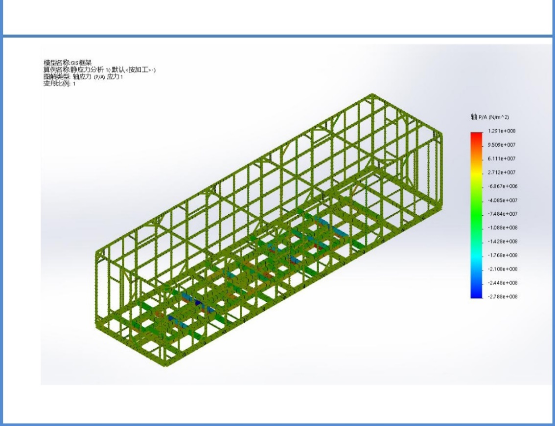
Figure 5. Deformation Cloud Diagram under Static Load
2) Lifting Strength Analysis
Simulations show that the light steel structure cabin meets the lifting strength requirement with a safety factor of 3. Without the safety factor, the maximum stress during lifting is 130.9MPa, below the yield strength of the material. With the safety factor of 3, the maximum stress during lifting is 312.4MPa, and the maximum plastic strain is 0.084%, with minimal plastic deformation that does not affect structural strength. The stress cloud diagram under lifting load is shown in Figure 6.
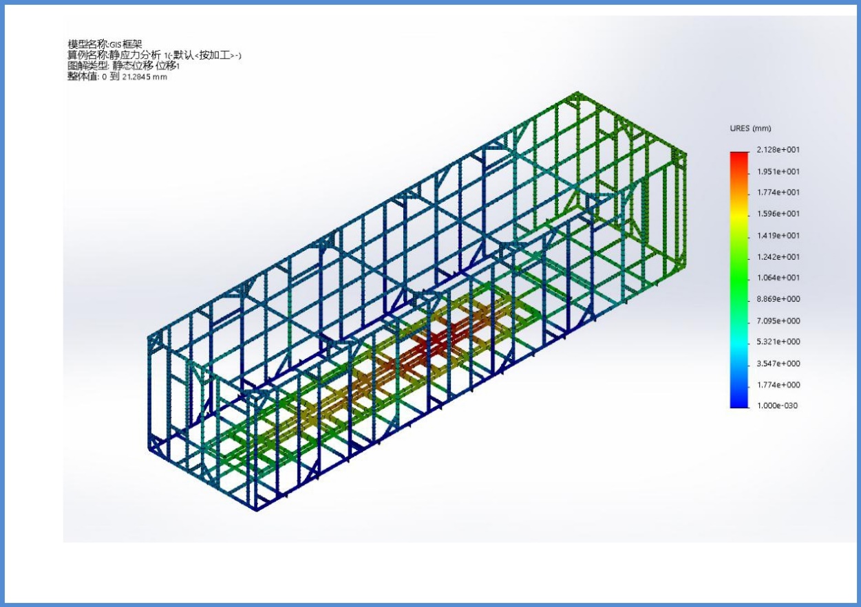
Figure 6. Stress Cloud Diagram under Lifting Load
3) Wind Load Resistance Analysis
Simulating 13-level wind conditions (maximum wind speed of 40m/s and wind pressure of 0.86KPa), the maximum stress on the long side panels is 148.6MPa, and on the top panels is 205.7MPa, both below the yield strength. The deformation cloud diagram under wind load is shown in Figure 7.
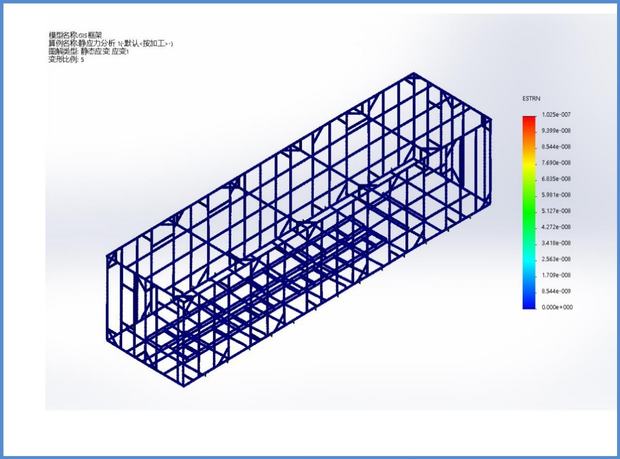
Figure 7. Deformation Cloud Diagram under Wind Load
4) Earthquake Resistance Analysis
Under 9-intensity earthquake simulation, the first-order natural frequency of the cabin is approximately 4.96Hz. With a static pull of 24 tons at the upper end of the side panel, the maximum displacement is 102.2mm, with minor plastic deformation in a limited area, not causing visible deformation. The deformation cloud diagram under earthquake load is shown in Figure 8.
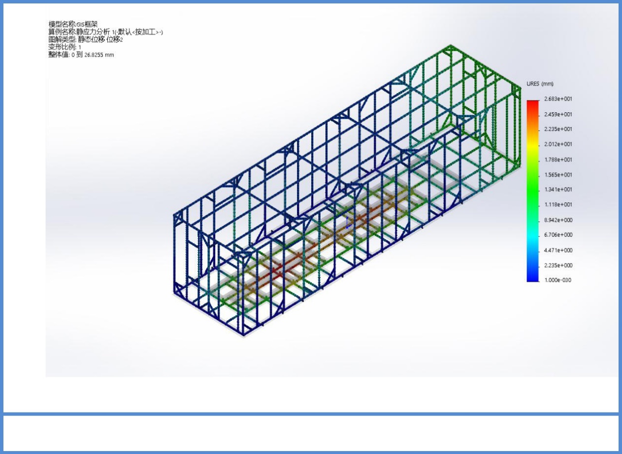
Figure 8. Deformation Cloud Diagram under Earthquake Load
2.3.2.Anti-corrosion design
The outer shell of the prefabricated cabin is designed to avoid dust and water accumulation. The top cover has a drainage slope of at least 5%, and drip edges prevent rainwater backflow. Minimizing exposed fasteners and sealing through-shell holes prevents water ingress and rust.
Prefabricated cabin metal components undergo phosphating anticorrosive treatment before installation to enhance the adhesion of the spray coating. The spraying process involves three layers of anticorrosive paint: the first layer is sprayed with epoxy-rich zinc primer, the second layer is sprayed with epoxy cloud iron intermediate paint rich in zinc powder, and the third layer is sprayed with aliphatic polyurethane anticorrosive topcoat, which boasts excellent weather resistance and durability.
The cabin base frame channel steel undergoes acid pickling and hot-dip galvanizing anticorrosive treatment, followed by heavy-duty anticorrosive treatment with asphalt paint to ensure that the base frame remains rust-free for 50 years. For the cabin protective paint, a super-heavy protection system paint treatment should be applied. The framework and roof are coated with marine paint, which can withstand salt spray for up to 6000 hours, meeting the corrosion protection requirements of the standard GB/T 30790-1998 Corrosion Protection of Paint and Varnish Systems for Steel Structures.
2.3.3.Electrical fire design
Between each prefabricated cabin, they are divided according to fire hazard categories and minimum fire resistance levels, with spacing meeting the requirements of fire regulations. The number of evacuation exits, evacuation width, and evacuation distance of prefabricated cabins all meet the requirements of the "Architectural Design Fire Protection Code". All cabin doors open towards the evacuation direction and are equipped with fire doors. Power cables, control cables, communication cables, and optical cables laid on cable trays are arranged in layers. Fireproof partitions should be installed between the upper and lower layers of power cables, with a fire resistance limit not less than 1 hour. Fireproof coatings, wrapping tapes, or fireproof panels should be applied at the junctions between cabin bodies.
To achieve an "unmanned" operating mode [9], a fire monitoring system is designed for the station, based on the principle of automatic alarm and control supplemented by manual alarm control. It consists of fire alarm controllers, manual control panels, dedicated fire linkage modules, manual sound and light alarms, various fire detectors, and other equipment. The fire alarm controller can display the trend, time, and status of fire occurrence in real time. When a fire occurs, the fire alarm detection device can automatically send a signal to the fire alarm controller, activate sound and light alarm devices to remind evacuees, and perform fire linkage control. The fire monitoring system reserves interfaces with other systems, primarily using switch quantity and communication methods, to transmit important fire signals to the booster station computer monitoring system.
3.Other key technologies
3.1.Vibration reduction between floating islands and equipment
According to local geological and hydrological data, the historical maximum and minimum water level difference on the lake surface is 1.5 meters, so there is a margin of about 2 meters for the fixed anchor points of the floating platform. This causes the floating platform to sway horizontally/vertically within a certain range. If the floating platform is rigidly connected to the equipment, long-term connection may lead to cracking and deformation at welding, bolting, or splicing points.
Special vibration isolation rubber pads are arranged between the floating platform and the equipment cabin. This pad consists of isolators and dampers. When surface waves approach, the floating platform sways accordingly, causing displacement of the cabin equipment relative to the floating platform. The isolators convert the sway of the cabin equipment into displacement relative to the floating platform, and the energy transmitted to the cabin equipment from the water surface is absorbed by the isolators and dampers. This significantly reduces distortion and bending of the cabin equipment, as well as reducing the degree of swinging, thereby reducing damage to the cabin equipment and ensuring its long-term normal operation. The special vibration isolation rubber pads have vertical bearing capacity, deformation performance, reasonable damping characteristics, reset function, and durability, greatly extending the service life of the water-floating power station [10]. The vibration reduction module designed and adopted by this station is shown in Figure 9.
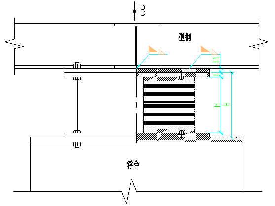
Figure 9. Schematic Diagram of Vibration Reduction Module
3.2.Balanced arrangement of equipment center of gravity
Since the floating platform floats on the water surface, the equipment cabins on the floating platform should not only meet the conventional substation design specifications but also try to align the total equipment center of gravity position with the floating platform center of gravity position to ensure that the equipment is basically horizontal when hoisted onto the floating platform. Subsequently, counterweights are hung to adjust the platform horizontally according to actual conditions, ensuring the long-term safe operation of the floating platform and the equipment inside the cabin.
Before determining the overall center of gravity position of the station, the weight and center of gravity positions of each module need to be confirmed one by one. Due to the different weight levels and center of gravity positions of each equipment cabin, their impact on the overall station's horizontal level varies. According to the priority of the impact level, arranged from the greatest to the least, the sequence is: switchgear cabin > secondary equipment cabin > grounding transformer cabin > SVG connection transformer cabin > living cabin > SVG control cabin. First, the weight and center of gravity of each module are determined, and a model is established based on the actual situation of each module using simulation software, followed by virtual assembly connection. The position parameters of the switchgear cabin are adjusted first to ensure that the center of gravity of the floating platform is in the center position, and then other cabins are added to their design positions. When the center of gravity position deviates, adjusting the position parameters of the switchgear cabin will keep the center of gravity of the floating platform always at the center. The entire layout must ensure that the electrical insulation distance of the equipment meets the specifications. The final positions of each equipment cabin are shown in Table 1, where the equipment codes are as follows: A: switchgear cabin, B: secondary equipment cabin, C: grounding transformer cabin, D: SVG connection transformer cabin, E: living cabin, F: SVG control cabin, G: floating platform.
Table 1. Position of Equipment Cabins
|
Equipment |
Weight (t) |
x-axis (m) |
y-axis (m) |
Z-axis (m) |
|
A |
46.5 |
10.3 |
11.79 |
1.805 |
|
B |
20 |
15.323 |
1.5 |
1.995 |
|
C |
18 |
3.547 |
21.11 |
1.65 |
|
D |
12.5 |
11.059 |
21.115 |
1.95 |
|
E |
11 |
4.75 |
1.5 |
1.534 |
|
F |
8 |
16.809 |
21.25 |
1.5 |
|
G |
116 |
10.122 |
12.144 |
1.783 |
3.3.Cable laying and fire protection
The photovoltaic array area includes four collector lines, which are laid through connecting channels along the active pontoons to the switchgear cabin. Cable laying in the high and low voltage distribution rooms and secondary equipment cabins uses cable trays, and the outgoing lines are laid through connecting channels along the active pontoons to the terminal tower.
Considering the influence of water surface on cable laying, the following measures are taken to avoid adverse factors:
The cables are equipped with carbon steel corrugated tubes to protect against ultraviolet radiation and splashing water, which could compromise cable insulation.
The cable laying adopts an S-shaped layout [11], with the floating tube connections designed as linear connections to prevent mechanical damage to the cables under temporary external forces. When water levels fluctuate, leaving displacement allowance between fixed and non-fixed cable ends in the S-shaped layout ensures the cables are not subjected to tensile damage.
During cable laying, a 14mm2 steel wire rope is laid alongside the cable path to absorb tension and prevent continuous stress on the cables when subjected to prolonged high tension.
The fixed ends of the cables in the S-shaped layout are secured using an anchoring system on the floating tubes to prevent excessive displacement of the cables and ensure uniform stress distribution on the fixing points. Ideally, the distance between two fixed ends should be 20m.
4.Conclusion
The technology of floating offshore switchyards integrates various disciplines and specialties, presenting engineering practicality and complexity. This paper, based on specific engineering examples, analyzes the floating platform system, anchoring system, switchyard, shock absorption between the floating platform and equipment, rational layout of the station, cable laying, and fire prevention measures from a design perspective. It attempts to address existing issues preliminarily, with the hope of providing some guidance to future endeavors. As a novel station construction model, floating offshore stations still require extensive research and practice in durability and reliability to ensure the safety of equipment and personnel.
References
[1]. Xin, S., Li, Z. P., et al. (2018). Application and benefit analysis of the "Fishery-Photovoltaic Complementary" project. Science and Technology Economy Guide.
[2]. Wang, F. Y. (2017). Technical characteristics and applications of floating photovoltaic power stations. Engineering Technology and Application.
[3]. Chen, D. P. (2017). New opportunities, new developments, and new challenges of floating photovoltaic power stations in China. Market Observation.
[4]. JTJ 215-1998. (1998). Port engineering load code [Standard].
[5]. GB 50330-2013. (2013). Technical specification for building slope engineering [Standard].
[6]. GB/T 20067-2006. (2006). Wire ropes -- Coarse diameter [Standard].
[7]. Bai, S. J., Wang, L., et al. (2017). Application of prefabricated substations in the power industry. Switchgear Industry Journal.
[8]. GB/T 30790-1998. (1998). Corrosion protection of steel structures by paint and clear coatings systems [Standard].
[9]. Li, W., & Li, J. (2016). Discussion on maintenance management mode of unmanned substations. Modern Industrial Economy and Informatization.
[10]. Li, X. D., & Ju, H. H. (2007). Review of mechanical properties of seismic isolation rubber bearings. Shanxi Construction.
[11]. Sun, J. (2017). Application technology and solutions of floating photovoltaic power stations. Energy Conservation and Environmental Protection.
[12]. Shang, C. Z. (2017). Analysis of design key points for floating photovoltaic power stations. Electric Power Survey and Design.
Cite this article
Mao,R.;Du,T.;Wei,S.;Bai,Z.;Zhao,Z. (2024). Design and engineering application of 35kV floating photovoltaic power station. Advances in Engineering Innovation,9,6-16.
Data availability
The datasets used and/or analyzed during the current study will be available from the authors upon reasonable request.
Disclaimer/Publisher's Note
The statements, opinions and data contained in all publications are solely those of the individual author(s) and contributor(s) and not of EWA Publishing and/or the editor(s). EWA Publishing and/or the editor(s) disclaim responsibility for any injury to people or property resulting from any ideas, methods, instructions or products referred to in the content.
About volume
Journal:Advances in Engineering Innovation
© 2024 by the author(s). Licensee EWA Publishing, Oxford, UK. This article is an open access article distributed under the terms and
conditions of the Creative Commons Attribution (CC BY) license. Authors who
publish this series agree to the following terms:
1. Authors retain copyright and grant the series right of first publication with the work simultaneously licensed under a Creative Commons
Attribution License that allows others to share the work with an acknowledgment of the work's authorship and initial publication in this
series.
2. Authors are able to enter into separate, additional contractual arrangements for the non-exclusive distribution of the series's published
version of the work (e.g., post it to an institutional repository or publish it in a book), with an acknowledgment of its initial
publication in this series.
3. Authors are permitted and encouraged to post their work online (e.g., in institutional repositories or on their website) prior to and
during the submission process, as it can lead to productive exchanges, as well as earlier and greater citation of published work (See
Open access policy for details).
References
[1]. Xin, S., Li, Z. P., et al. (2018). Application and benefit analysis of the "Fishery-Photovoltaic Complementary" project. Science and Technology Economy Guide.
[2]. Wang, F. Y. (2017). Technical characteristics and applications of floating photovoltaic power stations. Engineering Technology and Application.
[3]. Chen, D. P. (2017). New opportunities, new developments, and new challenges of floating photovoltaic power stations in China. Market Observation.
[4]. JTJ 215-1998. (1998). Port engineering load code [Standard].
[5]. GB 50330-2013. (2013). Technical specification for building slope engineering [Standard].
[6]. GB/T 20067-2006. (2006). Wire ropes -- Coarse diameter [Standard].
[7]. Bai, S. J., Wang, L., et al. (2017). Application of prefabricated substations in the power industry. Switchgear Industry Journal.
[8]. GB/T 30790-1998. (1998). Corrosion protection of steel structures by paint and clear coatings systems [Standard].
[9]. Li, W., & Li, J. (2016). Discussion on maintenance management mode of unmanned substations. Modern Industrial Economy and Informatization.
[10]. Li, X. D., & Ju, H. H. (2007). Review of mechanical properties of seismic isolation rubber bearings. Shanxi Construction.
[11]. Sun, J. (2017). Application technology and solutions of floating photovoltaic power stations. Energy Conservation and Environmental Protection.
[12]. Shang, C. Z. (2017). Analysis of design key points for floating photovoltaic power stations. Electric Power Survey and Design.