


1 Introduction
Superconducting electromagnetic suspension boasts advantages such as high operating speed, large suspension gaps, and high safety factors, making it a promising candidate for ultra-high-speed rail transport [1]. Traditional liquid helium cooling systems are complex in structure, operationally cumbersome, and expensive, with poor cooling uniformity when using cryocoolers. Adopting nitrogen cooling can effectively address these issues. Additionally, nitrogen undergoes a solid-solid phase transition at 35.6K, with a significant latent heat of transition, greatly increasing its heat capacity and enabling the absorption of substantial heat at low temperatures. By integrating nitrogen insulation and closed-loop operation technologies, high-temperature superconducting maglev trains can potentially achieve an operational model of charging and cooling at stations and closed-loop operation away from stations, thus eliminating the need for onboard cryocoolers and power supplies, significantly reducing the train's weight [2].
The Institute of Electrical Engineering of the Chinese Academy of Sciences plans to construct a high-overload electromagnetic suspension test line to provide a low-cost online testing environment for some extreme propulsion experiments [3,4]. In this paper, a transient thermal analysis model of the nitrogen cryogenic system is proposed. This model can calculate the temperature distribution during the cooling process and offline operation, providing reference and guidance for the design and optimization of nitrogen cryogenic systems.
2 Cryogenic system structure
The electromagnetic parameters of the magnet depend on the suspension and propulsion requirements of the electromagnetic suspension system. According to the project requirements, the magnet needs to generate a magnetic field of up to 5.0 T. The parameters of the track coils are shown in Table 1. To provide a stable low-temperature environment required for the long-term operation of the high-temperature superconducting magnet in the onboard cryogenic system for superconducting electromagnetic suspension trains, a cryogenic system capable of withstanding ton-level electromagnetic forces and having good insulation performance is typically required. Considering the project's application scenarios and design requirements, a magnet cryogenic system, as shown in Figure 1, was designed. Its main components include an outer Dewar, nitrogen chamber, cryocooler, binary current leads, aviation plug, various support rods, and inlet/outlet pipes.
Table 1. Track Coil Parameters
Tape |
|
Material |
REBCO/Stainless Steel |
Width |
3 mm |
Thickness |
0.1/0.03 mm |
Winding Pre-tension |
15/15 N |
Magnet |
|
Insulation Method |
Metal Insulation |
Number of Double Pancakes |
4 |
Number of Turns |
2880 |
Length of Straight Section |
205 mm |
Inner Radius of Arc Section |
90 mm |
Required Length of Tape |
3200 m |
Operating Temperature |
20-30 K |
Cryogenic System |
|
Cryocooler Model |
RDK-500B |
Cryocooler Power |
40/80 W @20/30 K |

Figure 1. Schematic Diagram of Magnet Cryogenic System
The nitrogen-cooled cryogenic system operates with refrigeration provided by a cryocooler and insulation maintained by nitrogen. An RKD-500B unit, installed on the Dewar flange (with accompanying compressor F70-H), supplies cooling capacity to the entire magnet system. The cooling power curve is depicted in Figure 2, with approximately 40 W at 20 K and around 80 W at 30 K. Inlet and outlet liquid nitrogen pipes are mounted on the Dewar flange to replenish nitrogen in the nitrogen chamber.
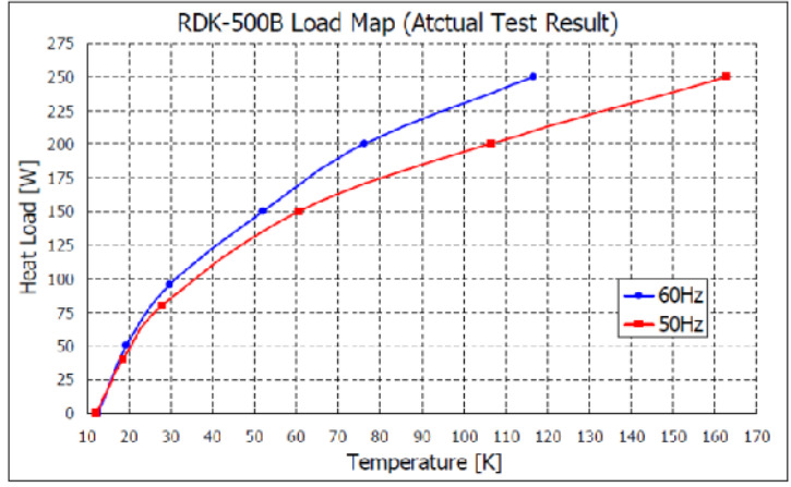
Figure 2. Refrigeration Power Curve
3 Low temperature system cooling simulation
Firstly, to verify whether the cryocooler meets the operational requirements of the prototype, a model of the nitrogen-cooled cryogenic system was established using COMSOL finite element software to simulate the cooling process. The power curve of the cryocooler was imported into COMSOL, assuming no liquid nitrogen input, and the temperature changes of the cold head and coil during the cooling process starting from ambient temperature are shown in Figure 3. After 22 hours of cooling, the temperature stabilizes with the cold head reaching a minimum of 18.5 K and the coil dropping to a minimum of 25.0 K. This meets the design requirements for operating temperatures, demonstrating that the cryocooler can satisfy the prototype's needs.
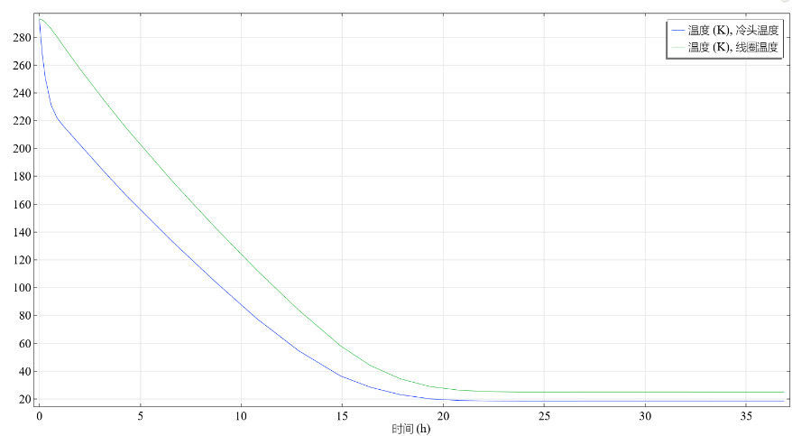
Figure 3. illustrates the average temperature variations of the cold head and coils during the prototype cooling process without liquid nitrogen injection.
Figure 4 shows the steady-state temperature distribution of the prototype after 36 hours of cooling. The temperature distribution is uniform in the nitrogen reservoir and superconducting switch, whereas the double cone support device exhibits temperature gradients due to its connection to the room temperature end. For further improvements during the later stages of construction, efforts are aimed at enhancing the cryogenic system's heat conduction structure. Additionally, a heat sink will be installed on the double cone support device to further enhance the heat conduction efficiency of the cryogenic system and reduce heat leakage.
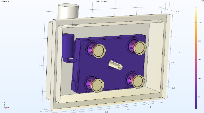
Figure 4. depicts the steady-state temperature distribution of the prototype under conditions without liquid nitrogen injection.
Subsequently, simulations were conducted with pre-injected liquid nitrogen into the nitrogen reservoir, stabilizing the entire system at 77 K. The cryogenic system begins cooling from 77 K onwards. Assuming the nitrogen container maintains a fixed temperature of 77 K, all components inside the container are initially assumed to be at this temperature. The external convection heat transfer condition is set to 5 W/(m2⋅K), with ambient temperature at room temperature. There is always a thermal contact resistance between two contacting surfaces. The thermal contact resistance between nitrogen and its container is set to 0.08 K⋅m2/W, between the heat conduction strap and nitrogen to 0.1 K⋅m2/W, and between the coil and nitrogen to 0.1 K⋅m2/W. The nitrogen container radiates heat at 8 W/m2. The nitrogen undergoes phase change at 63 K with 25.845 KJ/KG and at 35 K with 8 KJ/KG. To avoid additional coupling of electrical modules and enhance computational efficiency, a 2W magnet excitation loss is introduced in the coil as a generalized heat source, thereby avoiding multi-physics coupling calculations [7].
In finite element simulations calculating the temperature rise time of nitrogen, significant increases in heat capacity occur around 35.6 K due to solid-solid phase transitions. Therefore, phase transition studies generally employ two methods: equivalent heat capacity and enthalpy methods. The equivalent heat capacity method defines the latent heat of materials as a large specific heat capacity within the temperature range where phase transitions occur simultaneously. The enthalpy method uses enthalpy as a dependent function, which is then incorporated into the heat transfer differential equation to solve the temperature field. Given the complexity of obtaining an enthalpy function from experimental data, the equivalent heat capacity method is more convenient and effective for phase transition calculations when the enthalpy function is unavailable.
During material phase transitions, latent heat is absorbed or released, making phase transition problems a nonlinear transient heat transfer problem. According to the law of energy conservation, the differential form of the phase change heat transfer equation can be expressed as:
\( \frac{∂}{∂x}(k\frac{∂T}{∂x})+\frac{∂}{∂y}(k\frac{∂T}{∂y})+\frac{∂}{∂z}(k\frac{∂T}{∂z})+q=ρL\frac{∂f_{1}}{∂t}+ρC_{P}\frac{∂T}{∂t} \)
Here, \( \dot{q} \) is the volumetric heat generation rate, \( ρ \) is density, 𝐿 is latent heat, 𝐶𝑝 is specific heat, and 𝑓1 is the phase change rate [5].
Assuming 𝑓1 is linearly distributed within the phase change region, 𝑓1 can be expressed as:
\( f_{1}=\begin{cases}0, T≤T_{s} \\ \frac{T-T_{s}}{T_{l}-T_{s}}, T_{s}≤T≤T_{l} \\ 1, T≥T_{l}\end{cases} \)
Here, 𝑇𝑠 and 𝑇𝑙 are the starting and ending temperatures of the phase change. Simplifying the above equations yields:
\( \frac{∂}{∂x}(k\frac{∂T}{∂x})+\frac{∂}{∂y}(k\frac{∂T}{∂y})+\frac{∂}{∂z}(k\frac{∂T}{∂z})+q=ρ(C_{P}+\frac{L}{T_{l}-T_{s}})\frac{∂T}{∂t} \)
In the equation, represents the sensible heat capacity, defined as:
\( C_{p*e}=\begin{cases}C_{s}, T≤T_{s} \\ \frac{C_{s}-C_{1}}{2}+\frac{L}{T_{l}-T_{s}}, T_{s}≤T≤T_{l} \\ C_{1}, T≥T_{l}\end{cases} \)
Here, 𝐶𝑠 and 𝐶𝑙 denote the solid-state and liquid-state heat capacities of the phase-change material, respectively [6].
Under the condition of pre-injected liquid nitrogen for pre-cooling, the average temperature changes of the cold head and coils during the prototype cooling process are illustrated in Figure 5. After 8 hours of cooling, the prototype's temperatures stabilize, with the cold head reaching a minimum of 16.0 K and the coils dropping to a minimum of 24.0 K. Figure 6 depicts the steady-state temperature distribution of the prototype after 25 hours of cooling, meeting the design requirements for operational temperatures.
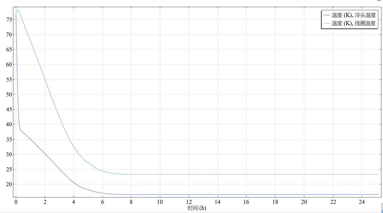
Figure 5. Average temperature variations of the cold head and coils during the prototype cooling process with liquid nitrogen injection.
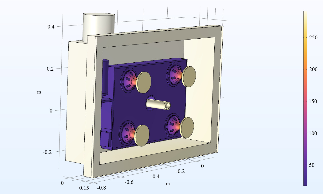
Figure 6. Steady-state temperature distribution of the prototype under conditions with liquid nitrogen injection.
4 Offline operation simulation of the cryogenic system
According to the practical application requirements of the cryogenic nitrogen-cooling system, the magnet may face conditions where it operates offline. Assuming the cryogenic system stabilizes at its lowest temperature with liquid nitrogen injection (as shown in Figure 6) and the magnet is magnetized to the target current for closed-loop operation, the refrigeration unit's cold head is then disconnected to achieve offline operation. Under these conditions, the system's boundary conditions are set similarly to those during the cooling process, but additional considerations are made for the heat generated during coil operation [8,9,10]. During offline operation, the average temperatures of the cold head and coils are depicted in Figure 7. In this scenario, the prototype reaches approximately 36 K after about 1 hour and approximately 45 K after about 2 hours. Figure 8 shows the steady-state temperature distribution of the prototype after 2 hours of offline operation. Simulation assessments confirm that the offline operation of the cryogenic system meets the designed operational duration requirements.
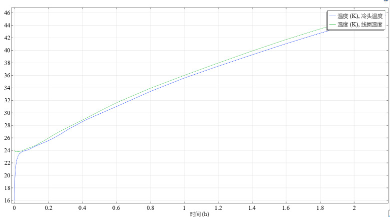
Figure 7. Average temperature variations of the cold head and coils during the prototype operation in offline conditions.
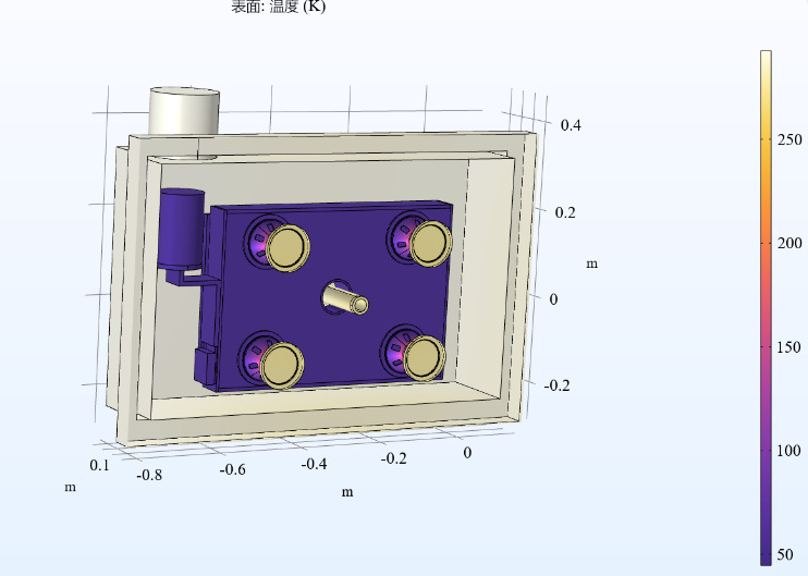
Figure 8. Steady-state temperature distribution of the prototype after 2 hours of offline operation.
5 Conclusion
In this study, we have completed the design and simulation of the nitrogen-cooling system for high-temperature superconducting magnets. Through simulation verification, we successfully lowered the average coil temperature to below 30 K. The study analyzed three operating conditions: refrigeration unit cooling, nitrogen cooling, and offline operation. The magnet operated in a closed loop at 25-40 K, meeting application requirements. The established model serves as a reference and guide for the design and optimization of cryogenic nitrogen-cooling systems."
References
[1]. Liu, S., Wang, L., Wang, L., et al. (2023). Review of electrically levitated trains and onboard superconducting magnets. Journal of Southwest Jiaotong University, 58(01), 734-753.
[2]. Dong, F., Huang, Z., Hao, L., et al. (2019). An on-board 2G HTS magnets system with cooling-power-free and persistent-current operation for ultrahigh speed superconducting maglevs. Scientific Reports, 9(11844). doi: 10.1038/s41598-019-48156-7.
[3]. Liu, S., Wang, L., Chen, Y., et al. (2023). R&D of on-board metal-insulation REBCO superconducting magnet for electrodynamic suspension system. Superconductor Science and Technology, 36(064002). doi: 10.1088/0953-2048/36/6/064002.
[4]. Wang, L., Wang, L., Hu, X., et al. (2023). Modeling and Analysis of Coil-type Electrodynamic Suspension Suitable for Narrow Gauge. IEEE Transactions on Transportation Electrification. doi: 10.1109/TTE.2023.1234567.
[5]. Pan, A., Wang, J., Zhang, X. (2014). Numerical analysis of phase change heat transfer based on equivalent heat capacity method and enthalpy method. Computer Simulation, 31(02), 315-319.
[6]. Ye, H., He, H., Ge, X., et al. (2004). Comparative study of analysis on melting process of phase change materials using enthalpy method and effective heat capacity method. Acta Energiae Solaris Sinica, (04), 488-491.
[7]. Liu, B., Ma, G., Li, S., et al. (2023). Mechanical-thermal coupling model of solid nitrogen cryostat for electrodynamic suspension system. Cryogenics, 134, 103727. doi: 10.1016/j.cryogenics.2023.103727.
[8]. Liu, S., Wang, L., Chen, Y., et al. (2024). Investigation of the effect of non-uniform stress distribution on the transient electromagnetic behavior of a no-insulation REBCO racetrack coil. Physica C: Superconductivity and its Applications, 617, 1354403. doi: 10.1016/j.physc.2024.1354403.
[9]. Liu, S., Wang, L., Chen, Y., et al. (2024). Investigation of the effect of difference in the characteristic resistance of DP coils on the field and losses of MI HTS magnets. Physica C: Superconductivity and its Applications, 622, 1354530. doi: 10.1016/j.physc.2024.1354530.
[10]. Liu, S., Wang, L., Wang, L., et al. (2024). Analysis of Charging Strategy for a Large Conduction-Cooled HTS Magnet under AC conditions. IEEE Transactions on Applied Superconductivity, 34(5), 4601707. doi: 10.1109/TASC.2024.4601707.
Cite this article
Wang,L.;Wang,L.;Xing,M. (2024). Transient thermal analysis model of nitrogen-cooled cryogenic system for superconducting electromagnetic suspension magnet. Advances in Engineering Innovation,9,17-23.
Data availability
The datasets used and/or analyzed during the current study will be available from the authors upon reasonable request.
Disclaimer/Publisher's Note
The statements, opinions and data contained in all publications are solely those of the individual author(s) and contributor(s) and not of EWA Publishing and/or the editor(s). EWA Publishing and/or the editor(s) disclaim responsibility for any injury to people or property resulting from any ideas, methods, instructions or products referred to in the content.
About volume
Journal:Advances in Engineering Innovation
© 2024 by the author(s). Licensee EWA Publishing, Oxford, UK. This article is an open access article distributed under the terms and
conditions of the Creative Commons Attribution (CC BY) license. Authors who
publish this series agree to the following terms:
1. Authors retain copyright and grant the series right of first publication with the work simultaneously licensed under a Creative Commons
Attribution License that allows others to share the work with an acknowledgment of the work's authorship and initial publication in this
series.
2. Authors are able to enter into separate, additional contractual arrangements for the non-exclusive distribution of the series's published
version of the work (e.g., post it to an institutional repository or publish it in a book), with an acknowledgment of its initial
publication in this series.
3. Authors are permitted and encouraged to post their work online (e.g., in institutional repositories or on their website) prior to and
during the submission process, as it can lead to productive exchanges, as well as earlier and greater citation of published work (See
Open access policy for details).
References
[1]. Liu, S., Wang, L., Wang, L., et al. (2023). Review of electrically levitated trains and onboard superconducting magnets. Journal of Southwest Jiaotong University, 58(01), 734-753.
[2]. Dong, F., Huang, Z., Hao, L., et al. (2019). An on-board 2G HTS magnets system with cooling-power-free and persistent-current operation for ultrahigh speed superconducting maglevs. Scientific Reports, 9(11844). doi: 10.1038/s41598-019-48156-7.
[3]. Liu, S., Wang, L., Chen, Y., et al. (2023). R&D of on-board metal-insulation REBCO superconducting magnet for electrodynamic suspension system. Superconductor Science and Technology, 36(064002). doi: 10.1088/0953-2048/36/6/064002.
[4]. Wang, L., Wang, L., Hu, X., et al. (2023). Modeling and Analysis of Coil-type Electrodynamic Suspension Suitable for Narrow Gauge. IEEE Transactions on Transportation Electrification. doi: 10.1109/TTE.2023.1234567.
[5]. Pan, A., Wang, J., Zhang, X. (2014). Numerical analysis of phase change heat transfer based on equivalent heat capacity method and enthalpy method. Computer Simulation, 31(02), 315-319.
[6]. Ye, H., He, H., Ge, X., et al. (2004). Comparative study of analysis on melting process of phase change materials using enthalpy method and effective heat capacity method. Acta Energiae Solaris Sinica, (04), 488-491.
[7]. Liu, B., Ma, G., Li, S., et al. (2023). Mechanical-thermal coupling model of solid nitrogen cryostat for electrodynamic suspension system. Cryogenics, 134, 103727. doi: 10.1016/j.cryogenics.2023.103727.
[8]. Liu, S., Wang, L., Chen, Y., et al. (2024). Investigation of the effect of non-uniform stress distribution on the transient electromagnetic behavior of a no-insulation REBCO racetrack coil. Physica C: Superconductivity and its Applications, 617, 1354403. doi: 10.1016/j.physc.2024.1354403.
[9]. Liu, S., Wang, L., Chen, Y., et al. (2024). Investigation of the effect of difference in the characteristic resistance of DP coils on the field and losses of MI HTS magnets. Physica C: Superconductivity and its Applications, 622, 1354530. doi: 10.1016/j.physc.2024.1354530.
[10]. Liu, S., Wang, L., Wang, L., et al. (2024). Analysis of Charging Strategy for a Large Conduction-Cooled HTS Magnet under AC conditions. IEEE Transactions on Applied Superconductivity, 34(5), 4601707. doi: 10.1109/TASC.2024.4601707.