


1 Introduction
Maglev trains, operating at high speeds, should aim to minimize the weight of the train body and improve the vehicle’s lift-to-weight ratio [1]. Currently, most onboard HTS (High-Temperature Superconducting) magnets based on ReBCO (Rare-earth Barium Copper Oxide) tapes operate in an open-loop mode, requiring onboard refrigerators and power supplies to maintain the current in the onboard superconducting magnets [2]. The superconducting switch (PCS) is a crucial component for the HTS coil to function in the persistent current mode (PCM) [3-5]. Utilizing superconducting magnet closed-loop operation technology can achieve a mode of operation without onboard power supplies, significantly reducing the weight of the train body. Thermal control superconducting switches are simple to control and do not generate magnetic fields, making them a popular direction in the development of superconducting switches.
A thermal control superconducting switch consists of a non-inductively wound superconducting coil and a heater. By heating the switch locally or entirely through the heater, the temperature of the superconducting switch exceeds its critical temperature, causing quenching and achieving the complete disconnection of the switch [6]. In this paper, a two-dimensional axisymmetric model of a superconducting switch using non-copper-plated stainless steel-encapsulated superconducting tape is established. Under the simulated liquid nitrogen conduction cooling environment, the simulation results show that the switch’s disconnection resistance is 4Ω, and the heater’s heating power is less than 1.15W.
2 Design and establishment of the superconducting switch model
2.1 Design of the superconducting switch
The excitation of a superconducting magnet essentially involves charging an RL circuit, so one important parameter of the superconducting switch is the disconnection resistance, which is the resistance of the switch when it is in a normal state. This resistance value directly affects the excitation efficiency of the magnet [7]. On the other hand, increasing the trigger energy of the heater can theoretically achieve a shorter disconnection time, but the cooling capacity of the conduction-cooled superconducting magnet system is limited. Typically, the second stage cold head of the refrigerator has only about 0.5W of power, making the trigger energy of the heater another critical parameter of the superconducting switch. Therefore, to achieve a higher disconnection resistance, the thickness of the metal layer can be reduced, and the length of the tape wound around the switch can be increased. The parameters of the high-temperature superconducting tape encapsulated in non-copper-plated stainless steel selected for the simulation are shown in Table 1.
Table 1. Geometric parameters of the superconducting tape for simulation
Stainless steel |
silver |
Hastelloy |
YBCO |
Ic @Self-field、77K |
Tape width |
lengths |
40um*2 |
1um*2 |
50um |
1um |
195A |
5mm |
3.2m |
2.2 Establishment of the electrothermal coupled finite element model
The superconducting tape and heating tape are alternately wound in reverse directions, which does not generate a magnetic field, thus ignoring the magnetic field effects [8]. The insulated heating tape is tightly wound in parallel with the high-temperature superconducting tape, ensuring that each turn of the superconducting switch coil is uniformly heated. When the Joule heat generated by the heating tape under trigger energy exceeds the cooling capacity conducted by the refrigerator, the temperature of the superconducting tape will rise. When the temperature of the superconducting layer exceeds the bypass temperature, part of the current in the superconducting layer will flow along the metal layer, generating more heat and causing the temperature to rise rapidly beyond its critical temperature, resulting in the complete quenching of the superconducting tape.
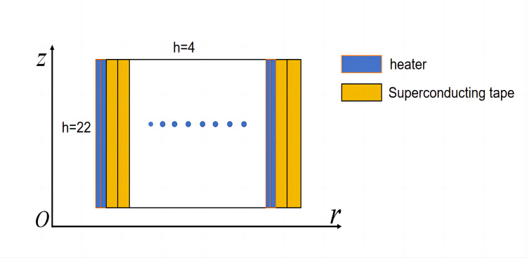
Figure 1. Schematic diagram of the two-dimensional cross-section of the superconducting switch
Using the magnetic field module and the solid heat transfer module of the finite element software COMSOL Multiphysics 6.0, a two-dimensional axisymmetric electrothermal coupled finite element model, as shown in Figure 1, was established to simulate and study the switching time and disconnection resistance under various conditions such as current flow, trigger energy, and cooling environment. On the left side and bottom of the two-dimensional axisymmetric cross-section, the switch coil is in direct contact with the framework, employing the heat flux boundary condition as shown in equation (1). The right side and top surface are in contact with filled paraffin, also using the heat flux boundary condition.
\( n\cdot (k(T)∇T)=h(T-T_{0}) \) (1)
Where h (W/m2·K) is the heat transfer coefficient between the framework and the switch coil, which can be measured experimentally; T0 is the initial temperature of 77K. The cooling of the superconducting switch coil mainly relies on conduction through the framework. Therefore, in the simulation calculations, h is set to 22 on the left side and bottom surface positions, and h is set to 4 on the right side and top surface to represent the difference in cooling capacity between them.
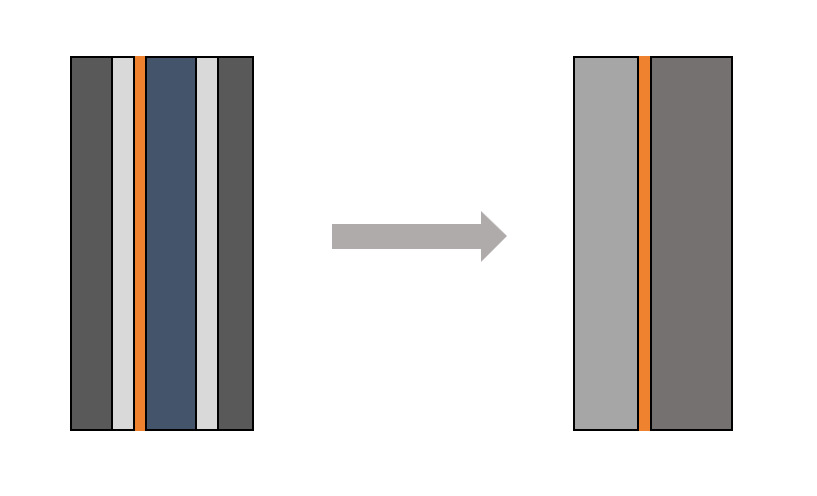
Figure 2. Schematic diagram of the homogenized cross-section of the superconducting tape
YBCO-coated superconducting materials are composite materials with complex structural characteristics such as multilayers and multiple components, among which the aspect ratio of the superconducting layer is extremely high. Therefore, to reduce the computational load and increase convergence, it is necessary to homogenize the model [9]. As shown in Figure 2, the actual superconducting tape can be homogenized into three parts: for the 5mm wide high-temperature superconducting tape, due to the high aspect ratio of the superconducting layer, it can be represented by a straight line. The density and specific heat capacity of the homogenized superconducting layer are averaged based on the mass ratio of each layer of material, as shown in equation (2):
\( ρ_{eq}=\frac{Σρ_{i}\cdot ⅆ_{i}}{d} \) \( C_{eq}(T)=\frac{ΣC_{pi}(T)\cdot ρ_{i}\cdot ⅆ_{i}}{ρ_{eq}\cdot d} \) (2)
Where d is the total thickness of the ReBCO-coated conductor; di is the thickness of the different material layers of the ReBCO-coated conductor; \( ρ_{i} \) and \( C_{pi}(T) \) are the density and specific heat capacity of the i-th layer, respectively. Using the high-temperature superconducting tape parameters shown in Table 1, the homogenized equivalent density \( ρ_{eq} \) on the left is 8734.3 kg/m³ and \( ρ_{eq} \) on the right is 8926 kg/m³, with the equivalent specific heat capacity varying with temperature. The equivalent electrical and thermal conductivity of the homogenized ReBCO-coated conductor in the radial and tangential directions are as shown in equation (3) [10]:
\( σ_{eqr}(T)=\frac{ⅆ}{Σd_{i}∕σ_{i}(T)} \) \( k_{eqr}(T)=\frac{ⅆ}{Σd_{i}∕k_{i}(T)} \)
\( σ_{eqφ}(T)=\frac{Σσ_{i}(T)\cdot ⅆ_{i}}{d} \) \( k_{eqφ}=\frac{Σk_{i}(T)\cdot ⅆ_{i}}{d} \) (3)
Where \( σ_{i}(T) \) and \( k_{i}(T) \) are the electrical and thermal conductivity of the i-th metal layer on the left and right sides of the superconducting layer, respectively, and both vary non-linearly with temperature.
3 Simulation results
The simulation results for a 20-turn high-temperature superconducting coil, with a switch current of 2A and a heating tape power of 1.1W, show the variation of the equivalent metal layer current for each turn of the coil, as illustrated in Figure 3. In the initial triggering phase of the heating tape (0-48s), none of the superconducting tapes quenched, and the current diversion in the equivalent metal layers was almost zero. At around 48.5s, the current in the equivalent metal layers of each turn rapidly increased to the switch current of 2A, and the superconducting switch fully opened within less than 3 seconds. The temperature distribution of the superconducting switch under a switch current of 2A and a heating tape power of 1.15W for the 20-turn high-temperature superconducting coil is shown in Figure 4.
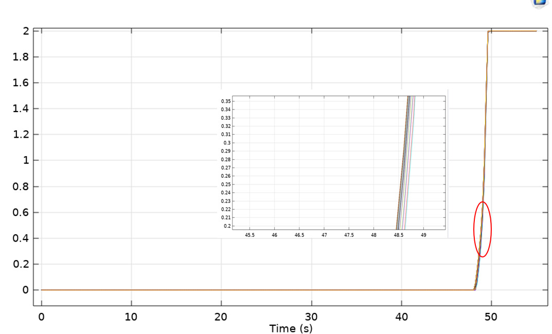
Figure 3. Current in the equivalent metal layer of each turn of the superconducting switch
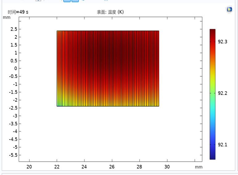
Figure 4. Temperature distribution of the superconducting switch
From Figure 4, it can be seen that the temperature distribution of the superconducting switch is consistent with our observation of the current diversion in the metal layers. From the beginning of heating to the disconnection of the switch, the temperature distribution within the switch cross-section is very uniform. This is because the second-generation high-temperature superconducting tape has a high thermal conductivity in the width direction, as shown in Figure 5, which is obtained under a heating tape power of 1.15W.
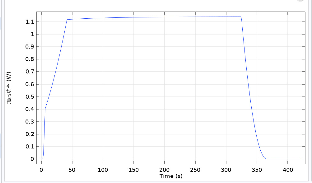
Figure 5. Heater heating power diagram
The simulation yielded the disconnection resistance of the superconducting switch, as shown in Figure 6. The obtained disconnection resistance value is high because we selected superconducting tape encapsulated in non-copper-plated stainless steel, eliminating the copper diversion layer. The resistance during disconnection is mainly determined by the thickness of the stainless steel and the length of the tape.
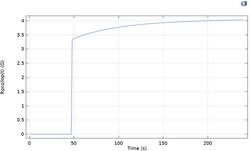
Figure 6. Disconnection resistance diagram of the superconducting switch
4 Conclusion
Through simulation calculations, it is demonstrated that the superconducting switch wound with 5m thin high-temperature superconducting tape encapsulated in non-copper-plated stainless steel achieves a disconnection resistance of nearly 4Ω at a temperature rise of approximately 30K in a simulated liquid nitrogen conduction cooling environment. The simulation results provide useful references for the feasibility of manufacturing pancake-type thermal control superconducting switches. Additionally, several useful conclusions were drawn:
(1) For this special structure of the high-temperature superconducting switch, the current and temperature distribution in each turn of the switch coil is relatively uniform, which can simplify the computational model;
(2) The heating power of the high-temperature superconducting switch is less than 1.2W, and the simulation results meet the application requirements for high-temperature superconducting electromagnetic suspension magnets;
(3) The disconnection time of the high-temperature superconducting switch is mainly determined by the trigger energy of the heating tape and the cooling environment. Further research is needed to determine the cooling boundary conditions that correspond to actual conditions in the calculations.
References
[1]. Liu, S., Wang, L., Wang, L., & others. (2023). A review of electric levitation trains and on-board superconducting magnets. Journal of Southwest Jiaotong University, 58(01), 734-753.
[2]. Michael, P. C., Qu, T., Voccio, J., Bascunan, J., Hahn, S., & Iwasa, Y. (2017). A REBCO Persistent-Current Switch (PCS): Test Results and Switch Heater Performance. IEEE Transactions on Applied Superconductivity, 27(4), 1-5.
[3]. Takahashi, K., & others. (2018). Performance of an HTS Persistent Current System for REBCO Pancake Coil. IEEE Transactions on Applied Superconductivity.
[4]. Geng, J., & others. (2016). HTS Persistent Current Switch Controlled by AC Magnetic Field. IEEE Transactions on Applied Superconductivity, 26(3).
[5]. Nakai, N., Yamano, S., Sakamoto, H., & Mukoyama, S. (2017). Persistent superconducting joint of REBCO tapes for HTS-MRI magnets. Presented at the 13th European Conference on Applied Superconductivity, Geneva, Switzerland, September 17-21.
[6]. Wang, Y. (2011). Fundamentals of superconducting power technology. Beijing: Science Press, 10-24, 90-97.
[7]. Heinrich, A., Muller, J., Hiebl, A., & Numssen, K., & others. (2001). YBCO Thin Films as Active High-Power Switches. IEEE Transactions on Applied Superconductivity, 11(1), 1952-1955.
[8]. Tosaka, T., Kuriyama, T., Yamaji, U., & others. (2004). Development of a Persistent Current Switch for HTS Magnets. IEEE Transactions on Applied Superconductivity, 14(2), 1218-1221.
[9]. Chan, W. K., Masson, P. J., Luongo, C. A., & others. (2009). Influence of Inter-Layer Contact Resistances on Quench Propagation in YBa2Cu3Ox Coated Conductors. IEEE Transactions on Applied Superconductivity, 19(3), 2490-2495.
[10]. Breschi, M., Ribani, P. L., Wang, X., & others. (2007). Theoretical explanation of the non-equipotential quench behavior in Y–Ba–Cu–O coated conductors. Superconductor Science & Technology, 20(4), L9-L11.
Cite this article
Wang,L.;Xing,M.;Wang,L. (2024). Model simulation analysis of superconducting switch applied to high-temperature superconducting electromagnetic suspension magnet. Advances in Engineering Innovation,9,42-46.
Data availability
The datasets used and/or analyzed during the current study will be available from the authors upon reasonable request.
Disclaimer/Publisher's Note
The statements, opinions and data contained in all publications are solely those of the individual author(s) and contributor(s) and not of EWA Publishing and/or the editor(s). EWA Publishing and/or the editor(s) disclaim responsibility for any injury to people or property resulting from any ideas, methods, instructions or products referred to in the content.
About volume
Journal:Advances in Engineering Innovation
© 2024 by the author(s). Licensee EWA Publishing, Oxford, UK. This article is an open access article distributed under the terms and
conditions of the Creative Commons Attribution (CC BY) license. Authors who
publish this series agree to the following terms:
1. Authors retain copyright and grant the series right of first publication with the work simultaneously licensed under a Creative Commons
Attribution License that allows others to share the work with an acknowledgment of the work's authorship and initial publication in this
series.
2. Authors are able to enter into separate, additional contractual arrangements for the non-exclusive distribution of the series's published
version of the work (e.g., post it to an institutional repository or publish it in a book), with an acknowledgment of its initial
publication in this series.
3. Authors are permitted and encouraged to post their work online (e.g., in institutional repositories or on their website) prior to and
during the submission process, as it can lead to productive exchanges, as well as earlier and greater citation of published work (See
Open access policy for details).
References
[1]. Liu, S., Wang, L., Wang, L., & others. (2023). A review of electric levitation trains and on-board superconducting magnets. Journal of Southwest Jiaotong University, 58(01), 734-753.
[2]. Michael, P. C., Qu, T., Voccio, J., Bascunan, J., Hahn, S., & Iwasa, Y. (2017). A REBCO Persistent-Current Switch (PCS): Test Results and Switch Heater Performance. IEEE Transactions on Applied Superconductivity, 27(4), 1-5.
[3]. Takahashi, K., & others. (2018). Performance of an HTS Persistent Current System for REBCO Pancake Coil. IEEE Transactions on Applied Superconductivity.
[4]. Geng, J., & others. (2016). HTS Persistent Current Switch Controlled by AC Magnetic Field. IEEE Transactions on Applied Superconductivity, 26(3).
[5]. Nakai, N., Yamano, S., Sakamoto, H., & Mukoyama, S. (2017). Persistent superconducting joint of REBCO tapes for HTS-MRI magnets. Presented at the 13th European Conference on Applied Superconductivity, Geneva, Switzerland, September 17-21.
[6]. Wang, Y. (2011). Fundamentals of superconducting power technology. Beijing: Science Press, 10-24, 90-97.
[7]. Heinrich, A., Muller, J., Hiebl, A., & Numssen, K., & others. (2001). YBCO Thin Films as Active High-Power Switches. IEEE Transactions on Applied Superconductivity, 11(1), 1952-1955.
[8]. Tosaka, T., Kuriyama, T., Yamaji, U., & others. (2004). Development of a Persistent Current Switch for HTS Magnets. IEEE Transactions on Applied Superconductivity, 14(2), 1218-1221.
[9]. Chan, W. K., Masson, P. J., Luongo, C. A., & others. (2009). Influence of Inter-Layer Contact Resistances on Quench Propagation in YBa2Cu3Ox Coated Conductors. IEEE Transactions on Applied Superconductivity, 19(3), 2490-2495.
[10]. Breschi, M., Ribani, P. L., Wang, X., & others. (2007). Theoretical explanation of the non-equipotential quench behavior in Y–Ba–Cu–O coated conductors. Superconductor Science & Technology, 20(4), L9-L11.