


1 Introduction
Superconducting EDS trains have significant advantages, such as large suspension gaps and high operating speeds, making them a promising mode of transportation [1]. In 2015, Japan’s newly developed L0-type low-temperature superconducting (LTS) EDS train successfully reached a speed of 603 km/h [2]. For superconducting EDS (Electrodynamic Suspension) systems, the core component is the onboard superconducting magnet, which provides traction, suspension, and guidance forces for the vehicle [3].
LTS magnets typically operate at temperatures below 4.2 K to maintain their superconducting state, requiring bulky refrigerators and expensive liquid helium (LHe) to reach operating temperatures. Second-generation HTS tapes, known for their excellent current-carrying capacity and mechanical strength, are widely used in winding HTS magnets. This allows HTS magnets to operate at temperatures ranging from 20 to 40 K, making radiation shielding and the removal of refrigerators possible [4].
The Institute of Electrical Engineering, Chinese Academy of Sciences plans to build a 20-meter-long high-load electromagnetic suspension test line, using metal-insulated (MI) HTS magnets for the onboard magnets [5]. For HTS EDS systems, critical current, magnetic field distribution, and charging delay are key parameters. In this paper, we introduce the electromagnetic design scheme of the onboard HTS magnets and accurately evaluate these parameters through simulations, providing theoretical support for the construction of the test line.
2 General design
The electromagnetic parameters of the onboard HTS magnet depend on the traction and suspension force requirements of the electromagnetic suspension system. According to these requirements, the magnet needs to generate a maximum magnetic field of 5.0 T. To produce the desired magnetic field shape, a racetrack-shaped structure is adopted for the onboard magnet. The designed parameters of the superconducting magnet are shown in Table 1.
Table 1. Superconducting Magnet Parameters
Tape |
|
Manufacturer |
Shanghai Superconductor Technology Co., Ltd. (SST) |
Material |
REBCO/Stainless Steel |
Width |
3 mm |
Thickness |
0.09/0.03 mm |
Winding Preload |
15/15 N |
Magnet |
|
Insulation Method |
Metal Insulation |
Number of Double Pancakes |
4 |
Number of Turns |
2880 |
Inductance |
4.23 H |
Straight Section Length |
205 mm |
Inner Radius of Arc Section |
90 mm |
Required Tape Length |
3200 m |
Operating Current |
170 A |
Operating Temperature |
20~30 K |
3 Critical current of the magnet
The most commonly used method for estimating the critical current of a magnet in engineering is the load line method. This method estimates the magnet’s critical current based on the critical current of the tape at the magnet’s most critical point, where the magnetic field magnitude and angle correspond to the minimum critical current [6].
The full-field angle characteristic method, on the other hand, thoroughly considers the magnitude and angle of the background magnetic field at different positions of the magnet to evaluate its critical current [7]. This method allows for a highly accurate analysis of the magnet’s margin, leading to more precise calculation results.
Using the full-field angle characteristic method, the critical current at various positions of the magnet was calculated, and the most critical point was selected to evaluate the magnet’s critical current. The simulation and evaluation were performed using the critical current field angle characteristic data at 30 K of the SST tape, publicly available from the Robinson Research Institute [8]. After evaluation, the load line and critical line of the magnet are shown in Figure 1, and the estimated critical current of the magnet is approximately 209 A. When measuring the critical current of a superconducting magnet, it is generally determined by observing the end voltage of the magnet to judge whether it has reached the critical current. Therefore, when measuring the critical current of the magnet, the result reflects an overall performance of the magnet, whereas the traditional load line method calculates based on a single most critical point, which may not align with actual measurements. If a certain point slightly exceeds the critical current of the tape, the magnet as a whole (in terms of end voltage) may not have reached quenching. Hence, the load line method usually yields a lower value than actual measurements, meaning the magnet’s critical current Ic >209 A, which far exceeds the operating current of 170 A.
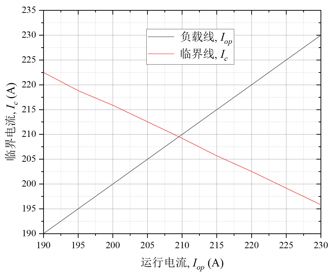
Figure 1. Calculation Results of the Magnet’s Critical Current
(Note: The horizontal axis represents the operating current, and the vertical axis represents the critical current. The red line indicates the critical line, while the other line represents the load line.)
4 Magnetic field distribution calculation
For simplicity, and based on symmetry, a 3D quarter model of the magnet was created in COMSOL software to reduce computation time. As shown in Figure 1.2, COMSOL was used to calculate the magnetic field distribution when the magnet operates at a current Iop=170 A. The maximum magnetic field is 6.51 T, achieving the target value. Additionally, the magnetic field at the center of the magnet reaches approximately 2.06 T.
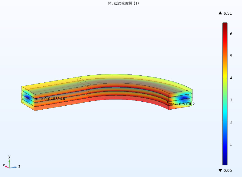
Figure 2. Magnetic Field Generated by the Magnet
5 Evaluation of magnet charging delay
Due to the removal of the inter-turn insulation layer, the MI HTS magnet experiences a delay between the magnetic field and the operating current during the charging process [9]. Therefore, it is necessary to evaluate the magnet’s charging delay and the losses during charging. As shown in Figure 1.3, an equivalent circuit model of the magnet was established [10]. Each double-pancake racetrack coil is considered an RL circuit, and the i-th double-pancake coil satisfies Kirchhoff’s voltage law:
\( \sum_{k=1,k≠i}^{N}\frac{dI_{θ,k}}{dt}M_{ki}+\frac{dI_{θ,i}}{dt}L_{i}+\frac{R_{sc,i}R_{m,i}}{R_{sc,i}+R_{m,i}}I_{θ,i}=I_{r,i}R_{c,i}\ \ \ (1) \)
Where, Iθ,i, Ir,i, Rm,i, Rsc,i, Rc,i, Li and Mki represent the circumferential current, radial current, metal layer resistance, superconducting layer resistance, inter-turn resistance, self-inductance, and mutual inductance between the i-th and k-th double-pancake coils, respectively. Rsc,i and Rc,i can be calculated using the following equations [11, 12]:
\( R_{sc,i}=E_{0}l_{i}\frac{I_{θ,i}^{n-1}}{I_{c,i}^{n}}\ \ \ (2) \)
\( R_{c,i}=\sum_{j=0}^{N_{t}}\frac{ρ_{ct}}{2(a_{1}+πr_{j})w_{0}}\ \ \ (3) \)
where E0 is the electric field constant (1×10⁻⁴ V/m), li is the length of the HTS tape used for winding the i-th double-pancake coil, and Ic,i represents the critical current of the i-th double-pancake coil. ρct is the contact resistivity, which can be calculated through a de-energizing experiment. For estimating the magnet’s charging delay and heating, we used the contact resistivity value (4000 μΩ·cm²) of conventional metal-insulated coils.
When the coil operates below its critical current and critical temperature, the superconducting layer resistance can be assumed to be zero for calculation convenience. The equation can be simplified as:
\( \sum_{k=1,k≠i}^{N}\frac{dI_{θ,k}}{dt}M_{ki}+\frac{dI_{θ,i}}{dt}L_{i}=I_{r,i}R_{c,i}\ \ \ (4) \)
Assuming the magnet is charged to the target current of 170 A at a rate of 0.1 A/s, the magnetic field change during the charging process is estimated as shown in Figure 1.4. From the figure, the charging delay of the magnet (the time for the magnetic field to reach 98% of the target field) is estimated to be less than 20 seconds, which is within the acceptable range. The metal insulation technique significantly reduces the magnet’s charging delay.
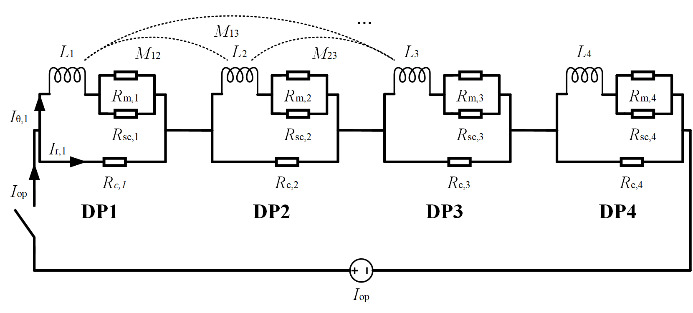
Figure 1.3. Equivalent Circuit Model of the Magnet
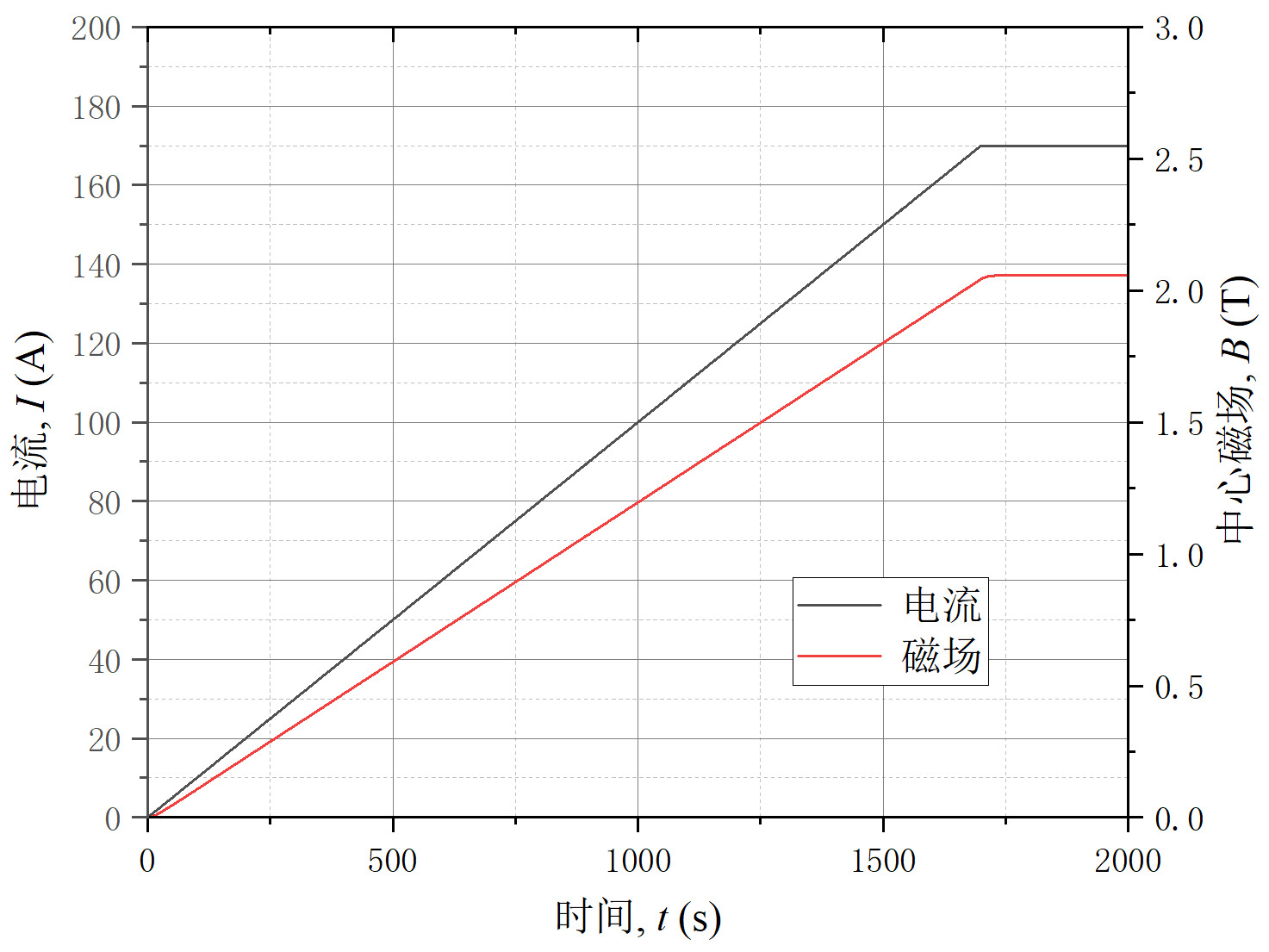
Figure 1.4. Changes in Current and Magnetic Field During Magnet Charging
(Note: The horizontal axis represents time, the left vertical axis represents current, and the right vertical axis represents the central magnetic field. The red line indicates the magnetic field, while the other line represents the current.)
6 Conclusion
In this paper, we completed the electromagnetic design of a high-temperature superconducting electromagnetic suspension magnet. Simulation evaluations show that the designed magnet has a critical current exceeding 209 A at an operating temperature of 30 K. At an operating current of 170 A, the magnet generates a maximum magnetic field of 6.51 T. The theoretical charging delay of the magnet is less than 20 seconds. The designed high-temperature superconducting electromagnetic suspension magnet meets the application requirements.
References
[1]. Deng, Z. G., Liu, Z. X., Li, H. T., & Zhang, W. H. (2022). Development status and prospect of maglev train. Journal of Southwest Jiaotong University, 455-474, 530.
[2]. Klaus, & Neumann. (2015). JR Tokai’s L0 maglev train sets world speed record. Superconductor Week, 29, 1-12.
[3]. Liu, S. X., Wang, L., Wang, L. Z., & Wang, Q. L. (2023). Review of research on electromagnetic suspension trains and onboard superconducting magnets. Journal of Southwest Jiaotong University, 58, 734-753.
[4]. Mizuno, K., Sugino, M., & Ogata, M. (2016). Experimental production and evaluation of racetrack coils for REBCO onboard magnet. Quarterly Report of RTRI, 57, 234-239.
[5]. Liu, S. X., Wang, L., Chen, Y., Wang, L. Z., Zhou, B. Z., Hu, X. N., Cheng, J. S., & Wang, Q. L. (2023). R&D of onboard metal-insulation REBCO superconducting magnet for electrodynamic suspension system. Superconductor Science and Technology, 36, 064002.
[6]. Dong, F. L., Huang, Z., Qiu, D. R., Hao, L. N., Wu, W., & Jin, Z. J. (2019). Design and analysis of a small-scale linear propulsion system for Maglev applications (2)–the HTS no-insulation magnets. IEEE Transactions on Applied Superconductivity, 29, 5200905.
[7]. Zhang, Z. L., Zhou, B. Z., Liu, J. H., Wang, L., & Wang, Q. L. (2022). Engineering-based design and fabrication procedure for mid-temperature REBCO magnets accommodating the strong Ic anisotropy. Superconductivity, 1.
[8]. Wimbush, S. C., & Strickland, N. M. (2017). A public database of high-temperature superconductor critical current data. IEEE Transactions on Applied Superconductivity, 27, 8000105.
[9]. Liu, S. X., Wang, L., Chen, Y., Zhou, B. Z., Wang, L. Z., Ji, X. Y., Hu, X. N., & Wang, Q. L. (2024). Investigation of the effect of non-uniform stress distribution on the transient electromagnetic behavior of a no-insulation REBCO racetrack coil. Physica C, 617, 1354403.
[10]. Hahn, S., Park, D. K., Bascunan, J., & Iwasa, Y. (2011). HTS pancake coils without turn-to-turn insulation. IEEE Transactions on Applied Superconductivity, 21, 1592-1595.
[11]. Rhyner, J. (1993). Magnetic properties and AC losses of superconductors with power-law current-voltage characteristics. Physica C, 212, 292-300.
[12]. Wang, X. D., Hahn, S., Kim, Y., Bascunan, J., Voccio, J., Lee, H., & Iwasa, Y. (2013). Turn-to-turn contact characteristics for an equivalent circuit model of no-insulation REBCO pancake coil. Superconductor Science and Technology, 26, 035012.
Cite this article
Wang,L.;Liu,S.;Wang,L.;Xing,M. (2024). Electromagnetic design of high-temperature superconducting electrodynamic suspension magnets. Advances in Engineering Innovation,9,57-61.
Data availability
The datasets used and/or analyzed during the current study will be available from the authors upon reasonable request.
Disclaimer/Publisher's Note
The statements, opinions and data contained in all publications are solely those of the individual author(s) and contributor(s) and not of EWA Publishing and/or the editor(s). EWA Publishing and/or the editor(s) disclaim responsibility for any injury to people or property resulting from any ideas, methods, instructions or products referred to in the content.
About volume
Journal:Advances in Engineering Innovation
© 2024 by the author(s). Licensee EWA Publishing, Oxford, UK. This article is an open access article distributed under the terms and
conditions of the Creative Commons Attribution (CC BY) license. Authors who
publish this series agree to the following terms:
1. Authors retain copyright and grant the series right of first publication with the work simultaneously licensed under a Creative Commons
Attribution License that allows others to share the work with an acknowledgment of the work's authorship and initial publication in this
series.
2. Authors are able to enter into separate, additional contractual arrangements for the non-exclusive distribution of the series's published
version of the work (e.g., post it to an institutional repository or publish it in a book), with an acknowledgment of its initial
publication in this series.
3. Authors are permitted and encouraged to post their work online (e.g., in institutional repositories or on their website) prior to and
during the submission process, as it can lead to productive exchanges, as well as earlier and greater citation of published work (See
Open access policy for details).
References
[1]. Deng, Z. G., Liu, Z. X., Li, H. T., & Zhang, W. H. (2022). Development status and prospect of maglev train. Journal of Southwest Jiaotong University, 455-474, 530.
[2]. Klaus, & Neumann. (2015). JR Tokai’s L0 maglev train sets world speed record. Superconductor Week, 29, 1-12.
[3]. Liu, S. X., Wang, L., Wang, L. Z., & Wang, Q. L. (2023). Review of research on electromagnetic suspension trains and onboard superconducting magnets. Journal of Southwest Jiaotong University, 58, 734-753.
[4]. Mizuno, K., Sugino, M., & Ogata, M. (2016). Experimental production and evaluation of racetrack coils for REBCO onboard magnet. Quarterly Report of RTRI, 57, 234-239.
[5]. Liu, S. X., Wang, L., Chen, Y., Wang, L. Z., Zhou, B. Z., Hu, X. N., Cheng, J. S., & Wang, Q. L. (2023). R&D of onboard metal-insulation REBCO superconducting magnet for electrodynamic suspension system. Superconductor Science and Technology, 36, 064002.
[6]. Dong, F. L., Huang, Z., Qiu, D. R., Hao, L. N., Wu, W., & Jin, Z. J. (2019). Design and analysis of a small-scale linear propulsion system for Maglev applications (2)–the HTS no-insulation magnets. IEEE Transactions on Applied Superconductivity, 29, 5200905.
[7]. Zhang, Z. L., Zhou, B. Z., Liu, J. H., Wang, L., & Wang, Q. L. (2022). Engineering-based design and fabrication procedure for mid-temperature REBCO magnets accommodating the strong Ic anisotropy. Superconductivity, 1.
[8]. Wimbush, S. C., & Strickland, N. M. (2017). A public database of high-temperature superconductor critical current data. IEEE Transactions on Applied Superconductivity, 27, 8000105.
[9]. Liu, S. X., Wang, L., Chen, Y., Zhou, B. Z., Wang, L. Z., Ji, X. Y., Hu, X. N., & Wang, Q. L. (2024). Investigation of the effect of non-uniform stress distribution on the transient electromagnetic behavior of a no-insulation REBCO racetrack coil. Physica C, 617, 1354403.
[10]. Hahn, S., Park, D. K., Bascunan, J., & Iwasa, Y. (2011). HTS pancake coils without turn-to-turn insulation. IEEE Transactions on Applied Superconductivity, 21, 1592-1595.
[11]. Rhyner, J. (1993). Magnetic properties and AC losses of superconductors with power-law current-voltage characteristics. Physica C, 212, 292-300.
[12]. Wang, X. D., Hahn, S., Kim, Y., Bascunan, J., Voccio, J., Lee, H., & Iwasa, Y. (2013). Turn-to-turn contact characteristics for an equivalent circuit model of no-insulation REBCO pancake coil. Superconductor Science and Technology, 26, 035012.