


1 Introduction
Traditional structural design methods in the construction industry often rely on 2D drawings and manual calculations. These methods are not only inefficient but also prone to errors. With the continuous growth in building scale and increasing complexity of structural forms, traditional methods struggle to meet the demands of modern architectural structural design. The emergence of Building Information Modeling (BIM) technology has brought revolutionary changes to structural design. BIM integrates design information from various disciplines, including architecture, structure, and MEP (mechanical, electrical, and plumbing), into a unified model, enabling interdisciplinary collaboration and information sharing. Additionally, BIM technology facilitates structural analysis, clash detection, and design optimization, significantly enhancing the intelligence level of structural design in architecture.
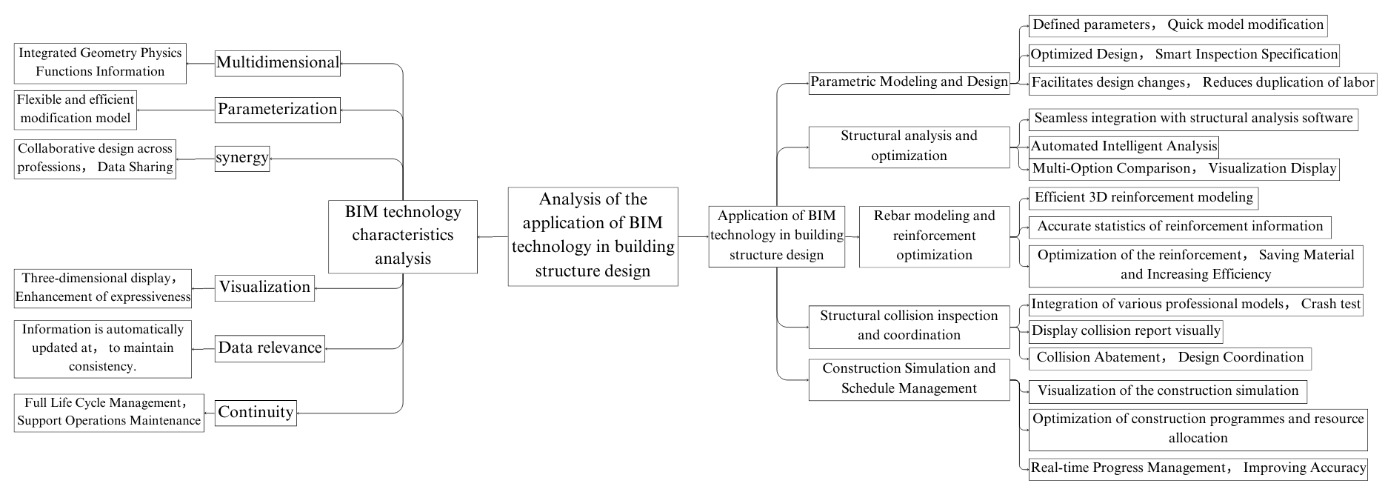
Figure 1. Application Process of BIM Technology in Structural Design
2 Characteristics of BIM technology
BIM (Building Information Modeling) technology, as the core of building information models, has significant characteristics such as multidimensionality, parameterization, collaboration, and visualization. Firstly, BIM technology is based on a 3D model that integrates the geometric, physical, and functional information of a building, achieving the organic unification of multidimensional data and providing a digital platform for managing the entire lifecycle of a building. Secondly, BIM technology uses parametric modeling, defining the parameters of building components and their interrelationships, which makes model modification and updating more flexible and efficient, greatly improving design efficiency and quality. Thirdly, BIM technology emphasizes collaborative design and data sharing between various disciplines. By exchanging and sharing information on a unified platform, design errors and conflicts are reduced, and the collaboration efficiency of all project participants is improved [1]. At the same time, BIM technology presents various building information through intuitive 3D visualization, enhancing the expressiveness and readability of design solutions, facilitating understanding and communication among all parties involved. Finally, BIM technology also features data correlation and continuity. The information within the model is interrelated, and when one part changes, the relevant information is automatically updated, ensuring data consistency and accuracy. Furthermore, the BIM model can be continuously enriched and perfected throughout the building's lifecycle, providing reliable data support for the operations and maintenance phase.
3 Application of BIM technology in structural design
3.1 Parametric modeling and design
In BIM technology, parametric modeling and design refers to the creation of intelligent 3D models by defining the parameters of building components and their interrelationships, thereby achieving efficient, flexible, and optimized design. During the parametric modeling process, designers can quickly modify and update the model by adjusting the parameters, without needing to redraw or rebuild the model. For example, when designing a rectangular steel column, parameters such as section size, length, and material can be defined. If the section size needs to be modified, the corresponding parameter value can simply be changed, and the model will automatically update, along with the relevant drawings and documents. This parametric design approach significantly increases design efficiency and reduces repetitive work [2]. At the same time, parametric modeling can also achieve optimization and intelligence in design. By establishing reasonable parameter relationships and rules, the system can automatically check if the design meets the code requirements and provide optimization suggestions. For instance, when designing a steel structure, parameters such as span, load, and material can be set, and the system can automatically calculate the optimal section size and arrangement, as shown in the following table:
Table 1. Steel Structure Design Parameters
Span (m) |
Load (kN/m) |
Material |
Optimal Section (mm) |
Weight (kg/m) |
6 |
20 |
Q345 |
H300×300×10×15 |
106.94 |
8 |
20 |
Q345 |
H400×400×13×21 |
193.81 |
10 |
20 |
Q345 |
H500×500×16×26 |
310.27 |
Through parametric design, different design schemes can be quickly compared for economic and safety considerations, allowing the selection of the most optimal design. Furthermore, parametric modeling also facilitates design changes and optimizations. In practical engineering projects, design changes are often encountered. If traditional 2D design methods are used, a large number of drawings and documents need to be revised, resulting in a huge workload. However, with parametric modeling, only the relevant parameters need to be adjusted, and the model and documents will automatically update, significantly reducing the workload and risk of errors.
3.2 Structural analysis and optimization
In building structural design, BIM technology demonstrates its powerful advantages and potential in structural analysis and optimization. By seamlessly integrating the BIM model with structural analysis software, the automation and intelligence of structural design can be achieved. Designers can create structural models in BIM software, defining parametric information such as material properties, section sizes, and load conditions [3]. Next, the BIM model is imported into structural analysis software, where the software can automatically identify the structural components, connections, and load information in the model, generating a finite element analysis model. Designers can perform various types of structural analysis under different working conditions, such as static analysis, dynamic analysis, and stability analysis. For example, in the structural analysis of a certain high-rise building using the BIM model, the following results were obtained:
Table 2. Structural Analysis of a High-Rise Building Using BIM Model
Working Condition |
Maximum Displacement (mm) |
Inter-story Drift Angle |
Shear Force (kN) |
Overturning Moment (kN·m) |
Wind Load |
128.6 |
1/1523 |
8523 |
538200 |
Earthquake Load |
96.8 |
1/2019 |
12367 |
792600 |
According to the analysis results, designers can evaluate the safety and comfort of the structure and carry out structural optimization. For example, adjustments to the structural layout, component sections, and material selection can be made to improve the structure's lateral force resistance and cost-effectiveness. The optimized structural model can be imported back into BIM software for parametric modifications and updates. Through repeated iterations and optimizations of the BIM model and structural analysis software, the optimal structural design solution can be obtained [4, 5]. Additionally, BIM technology allows for the comparison of multiple design options and visual presentations. By conducting a comprehensive evaluation of factors such as structural performance, cost, and construction difficulty, the best design solution can be selected. For example, for the high-rise building mentioned above, the designer proposed three optimization schemes:
Table 3. Design Schemes for a High-Rise Building
Scheme |
Maximum Displacement (mm) |
Inter-story Drift Angle |
Steel Usage (t) |
Concrete Usage (m³) |
Cost (10,000 Yuan) |
Scheme 1 |
118.2 |
1/1658 |
2682 |
12360 |
4523 |
Scheme 2 |
106.5 |
1/1843 |
2527 |
13108 |
4336 |
Scheme 3 |
95.4 |
1/2056 |
2438 |
13425 |
4285 |
Through BIM's visual display and multi-scheme comparison, designers can intuitively present the pros and cons of each scheme to the owner and other professionals, promoting communication and decision-making. Ultimately, after a comprehensive evaluation, Scheme 3 was selected as the optimal design solution.
3.3 Reinforcement modeling and Rebar optimization
Traditional reinforcement design and drafting work is cumbersome, time-consuming, and prone to errors. However, the use of BIM technology can significantly improve work efficiency and accuracy. First, after completing the parametric modeling of structural components, designers can use the reinforcement modeling tools in BIM software to directly create 3D rebar models within the components based on design specifications and engineering requirements. The software can automatically recognize the geometric information and loading characteristics of the components, generating reinforcement layouts that meet the required standards. For example, for a beam with an 8-meter span and a 0.6-meter height, a reinforcement ratio of 1.2%, concrete strength grade of C30, and steel grade HRB400, the BIM software can automatically generate the following reinforcement layout: four longitudinal tension steel bars with a diameter of 20mm, two longitudinal stirrups with a diameter of 12mm, and hoop reinforcement with a diameter of 8mm and a spacing of 100mm for double-leg stirrups. Designers can visually inspect the rebar layout through the 3D view to check its rationality and make necessary adjustments and optimizations. At the same time, BIM software can automatically handle details such as the extension, anchorage, and lap of rebar, ensuring the reliability of the rebar connections and compliance with construction requirements. After completing the reinforcement modeling, BIM software can automatically generate detailed rebar statistical tables and cutting lists, including specifications, quantities, lengths, and weights of the rebar. This greatly reduces the workload and error rate. For example, for a 20-story frame structure residential building, BIM software can calculate that the total weight of longitudinal tension rebar in the beams is 120 tons, the total weight of stirrups is 35 tons, the total weight of longitudinal rebar in the columns is 280 tons, the total weight of stirrups is 60 tons, the total weight of vertical rebar in the walls is 75 tons, and the total weight of horizontal rebar is 25 tons. These precise data provide a reliable basis for project cost estimation and material procurement. Furthermore, reinforcement optimization based on the BIM model is also an important application. By exchanging data with structural analysis software, the rebar layout information can be compared and optimized with structural calculation results. Weak areas and redundant zones in the rebar layout can be identified, and parameters such as rebar diameter, spacing, and arrangement can be adjusted to achieve material savings and efficiency. For example, adjusting the spacing of hoop reinforcement in a beam from 100mm to 150mm can reduce the use of stirrups by 20% without significantly affecting the shear capacity of the beam. Similarly, under the condition that the minimum rebar ratio is met, reducing the diameter of the tensile rebar in a slab from 12mm to 10mm can reduce the rebar usage by 15%, with little effect on the slab's bending capacity. Through such detailed reinforcement optimization, materials can be saved to the maximum extent, and economic benefits can be increased while ensuring the structural safety and functionality.
3.4 Structural clash detection and coordination
In traditional design processes, design drawings from different disciplines are often separate, making it difficult to comprehensively consider spatial relationships and interface issues between disciplines. This can lead to clashes and conflicts in the design. However, by using BIM technology, the designs of different disciplines can be visually checked and coordinated within the 3D model, allowing clashes to be detected and resolved early, thus avoiding design changes and rework. First, the models of various disciplines such as architecture, structure, and MEP (mechanical, electrical, and plumbing) are integrated within the BIM software to form a complete 3D building information model. Then, using the clash detection tool within the BIM software, automated clash detection is performed on the model. The software can automatically identify geometric collisions and spatial interferences in the model based on predefined rules and tolerances, and generate detailed clash reports. These reports include the type of collision, location, component information, etc., and visually display the clashes in the 3D model using different color markers. For example, in the BIM model of a large commercial complex project, the clash detection revealed the following issues:
Table 4. BIM Model Clash Detection Report for a Large Commercial Complex Project
Collision Type |
Number of Collisions |
Typical Locations |
Beam and Duct |
128 |
Underground garage, main podium |
Column and Drainage Pipe |
56 |
Tower stairwells, restrooms |
Wall and Cable Tray |
92 |
Office areas, public corridors |
Floor Slab and Air Conditioning Duct |
76 |
Tower standard floors, podium dining areas |
Based on the results of the clash detection, designers can specifically address clashes and coordinate designs. For example, for the clash between beams and ducts, the layout or height of the ducts can be adjusted to bypass the beam area; for the clash between columns and drainage pipes, the direction or positioning of the drainage pipes can be modified to avoid the column; for the clash between walls and cable trays, the installation height of the cable trays or the reserved openings can be adjusted to offset the wall; for the clash between floor slabs and air conditioning ducts, the layout floor height or direction of the ducts can be altered to avoid the floor slab. During the clash resolution and design coordination process, BIM software can provide real-time visual feedback, allowing designers to intuitively view the effects of the adjustments and communicate and confirm with the other disciplines. After multiple rounds of clash detection and coordination, the clash issues in the aforementioned project were effectively resolved, and the pass rate of the clash detection reached over 98%. This not only improved the design quality and construction efficiency but also reduced design changes and on-site rework, laying a solid foundation for the smooth implementation of the project. Below is a comparison of the number of clashes before and after optimization:
Table 5. BIM Model Clash Detection Optimization for a Large Commercial Complex Project
Collision Type |
Number of Collisions Before Optimization |
Number of Collisions After Optimization |
Reduction Rate |
Beam and Duct |
128 |
5 |
96.1% |
Column and Drainage Pipe |
56 |
2 |
96.4% |
Wall and Cable Tray |
92 |
3 |
96.7% |
Floor Slab and Air Conditioning Duct |
76 |
1 |
98.7% |
It can be seen that through the use of BIM technology for clash detection and coordination, the design clash issues across disciplines have been significantly improved, with the number of clashes reduced by an average of over 97%. This fully demonstrates the significant value and application prospects of BIM technology in building design.
3.5 Construction simulation and schedule management
Traditional construction management primarily relies on 2D drawings and written descriptions, making it difficult to intuitively reflect the dynamic changes of the construction process and key milestones. This often leads to delays in progress and resource wastage. However, by using BIM technology, visualized construction simulations and schedule management can be performed based on a 3D model, significantly improving construction efficiency and quality. First, based on the construction organization design and schedule plan, a construction schedule model is created in BIM software. Building components are linked to construction tasks, and attributes such as task duration, sequence, and resource requirements are defined. Then, using the construction simulation tools in BIM software, the construction process is dynamically simulated and visually displayed. The software can automatically generate realistic construction animations based on the set construction sequence and time parameters, providing a clear representation of the entire construction process. Designers can observe each phase of construction through the animation, including site layout, material stacking, mechanical equipment, temporary facilities, safety protection, and more, enabling timely identification of issues and risks in the construction process, and optimizing construction plans and resource allocation. For example, by simulating and analyzing the tower crane’s position and lifting radius, the tower crane layout can be optimized, reducing blind spots and interferences during lifting. Simulating the erection and dismantling of scaffolding can optimize the scaffolding plan, reducing safety hazards and material wastage. Simulating the dynamic layout of the construction site can optimize site management, reducing cross-operations and downtime. At the same time, BIM-based construction schedule management greatly enhances the efficiency and accuracy of schedule control. By linking with the construction schedule model, the completion status of various tasks and resource usage can be monitored in real time, and intuitive progress control charts, such as Gantt charts and S-curves, can be generated. Managers can promptly understand the progress, detect deviations and anomalies, and take corrective actions as needed. For instance, if the actual progress of a critical task is behind the planned schedule, the sequence of subsequent tasks can be adjusted, or additional resources can be allocated to catch up. Similarly, if the actual consumption of a particular material exceeds the budget, cost-saving measures can be taken by optimizing the design or controlling on-site wastage. Through BIM technology’s construction simulation and schedule management, the construction process can be visualized, controlled, and refined, ultimately improving construction management levels and project outcomes.
4 Conclusion
In conclusion, the application of BIM technology in architectural structural design comprehensively demonstrates its significant value and broad prospects in revolutionizing design processes, improving design efficiency, optimizing design schemes, ensuring construction quality, and enhancing management levels. This is evident in various aspects such as parametric modeling, structural analysis and optimization, rebar modeling and reinforcement, clash detection and coordination, and construction simulation and schedule management. With the continuous development and improvement of BIM technology, and its deep integration with emerging technologies such as cloud computing, big data, the Internet of Things, and artificial intelligence, its application in architectural structural design—and in the construction industry as a whole—will undoubtedly become more profound and widespread. This will drive the industry toward further advancements in digitalization, intelligence, collaboration, and refinement.
References
[1]. Zhao, Y., & Huang, S. (2024). Research on the application of BIM technology in building engineering structural design. Urban Construction Theory Research (Electronic Edition), (06), 51-53.
[2]. Zong, Y., & Yang, L. (2024). The application of BIM technology in modern building engineering structural design. Engineering Technology Research, (04), 225-227.
[3]. Gao, Q. (2024). Research on building structural design methods based on BIM technology. Engineering Technology Research, (01), 188-190.
[4]. Fang, J. (2023). Exploration of BIM technology in building structural design. China Residential Facilities, (11), 160-162.
[5]. Jiang, J., & Wang, B. (2023). An analysis of the application of BIM technology in building structural design. Urban Construction Theory Research (Electronic Edition), (15), 79-81.
Cite this article
Ma,L.;Huo,Y.;Zhang,Y.;Cheng,W. (2024). Analysis of BIM technology applications in structural design. Advances in Engineering Innovation,14,55-59.
Data availability
The datasets used and/or analyzed during the current study will be available from the authors upon reasonable request.
Disclaimer/Publisher's Note
The statements, opinions and data contained in all publications are solely those of the individual author(s) and contributor(s) and not of EWA Publishing and/or the editor(s). EWA Publishing and/or the editor(s) disclaim responsibility for any injury to people or property resulting from any ideas, methods, instructions or products referred to in the content.
About volume
Journal:Advances in Engineering Innovation
© 2024 by the author(s). Licensee EWA Publishing, Oxford, UK. This article is an open access article distributed under the terms and
conditions of the Creative Commons Attribution (CC BY) license. Authors who
publish this series agree to the following terms:
1. Authors retain copyright and grant the series right of first publication with the work simultaneously licensed under a Creative Commons
Attribution License that allows others to share the work with an acknowledgment of the work's authorship and initial publication in this
series.
2. Authors are able to enter into separate, additional contractual arrangements for the non-exclusive distribution of the series's published
version of the work (e.g., post it to an institutional repository or publish it in a book), with an acknowledgment of its initial
publication in this series.
3. Authors are permitted and encouraged to post their work online (e.g., in institutional repositories or on their website) prior to and
during the submission process, as it can lead to productive exchanges, as well as earlier and greater citation of published work (See
Open access policy for details).
References
[1]. Zhao, Y., & Huang, S. (2024). Research on the application of BIM technology in building engineering structural design. Urban Construction Theory Research (Electronic Edition), (06), 51-53.
[2]. Zong, Y., & Yang, L. (2024). The application of BIM technology in modern building engineering structural design. Engineering Technology Research, (04), 225-227.
[3]. Gao, Q. (2024). Research on building structural design methods based on BIM technology. Engineering Technology Research, (01), 188-190.
[4]. Fang, J. (2023). Exploration of BIM technology in building structural design. China Residential Facilities, (11), 160-162.
[5]. Jiang, J., & Wang, B. (2023). An analysis of the application of BIM technology in building structural design. Urban Construction Theory Research (Electronic Edition), (15), 79-81.