


1. Introduction
The MacPherson suspension system typically consists of a shock absorber, coil spring, stabilizer bar, lower control arm, and steering knuckle. Due to its high space utilization, excellent handling performance, and effective shock absorption, it is widely used in the front-wheel suspension of automobiles. As an elastic component, the coil spring plays a crucial role in supporting the vehicle's weight and absorbing road impacts. During operation, the spring undergoes repeated compression and rebound, enduring cyclic alternating loads, with fatigue fracture being the most common failure mode [1-2].
In a full-vehicle accelerated corrosion test conducted by an automotive company, the front coil spring fractured at approximately 0.8 turns from the lower end after 57 test cycles, as shown in Figure 1. However, this coil spring had successfully passed the vehicle structural durability test and a 200,000-cycle test at frequencies of 1-6 Hz on a test rig without failure, meeting the required fatigue life standards. To investigate the cause of the failure during the corrosion test, a comprehensive failure analysis was performed, including chemical composition assessment, hardness testing, macro and micro fracture morphology examination, metallographic structure evaluation, and shot peening process inspection.
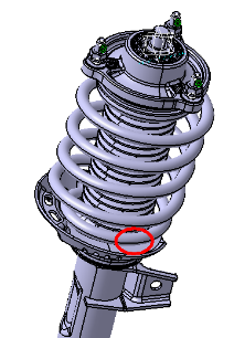
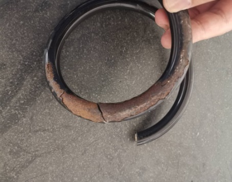
Figure 1. Fractured Coil Spring
2. Coil spring manufacturing process
The coil spring is made of alloy spring steel 55CrSi, with a wire diameter of Φ13.4 mm. The manufacturing process involves cold coiling, tempering, hot pre-setting, shot peening, cold pre-setting, pre-treatment, and powder coating. The required microstructure is tempered troostite, with a hardness specification of 52-56 HRC, and the decarburization layer depth must not exceed 1% of the wire diameter.
3. Failure cause analysis
3.1. Chemical composition inspection
The chemical composition analysis of the failed coil spring confirmed that it met the technical specifications for 55CrSi material, as shown in Table 1.
Table 1. Chemical Composition Analysis of the Front Coil Spring (Mass Fraction, %)
Element | C | Si | Mn | Cr | P | S |
Technical Requirement | 0.5~0.6 | 1.2~1.6 | 0.5~0.8 | 0.5~0.8 | ≤0.03 | ≤0.03 |
Measured | 0.53 | 1.35 | 0.72 | 0.69 | 0.07 | 0.01 |
3.2. Surface hardness inspection
The coil spring in question was manufactured using a cold coiling process, and its hardness was tested using a Rockwell hardness tester (HR-150A) on a cross-section taken from the fracture surface. The measured hardness values were HRC 54.2, 54.7, 56.3, 57.0, 54.6, 55.9, 57.5, 55.3, 57.4, 54.8, with an average hardness of HRC 55.8. Some localized areas of the cross-section reached HRC 57 or above, indicating excessive hardness.
3.3. Metallographic examination
A sample from the fracture surface was cut and polished following the ASTM E 3-01 standard for metallographic analysis. The microstructure was confirmed to be tempered troostite, which met the required metallurgical specifications, as shown in Figure 2.
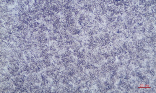
Figure 2. Metallographic Structure (500×)
The decarburization layer depth was measured according to the JIS G0558 standard for steel decarburization measurement. The results confirmed that there was no surface decarburization, as shown in Figure 3.
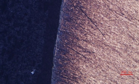
Figure 3. Surface Decarburization Depth (100×)
3.4. Shot peening residual stress analysis
Shot peening is a common surface treatment process used to enhance the mechanical properties of metal materials. This process involves high-pressure air propelling steel shot at the metal surface to induce plastic deformation and introduce a compressive residual stress layer, which helps counteract tensile stresses caused by external loads. This is particularly beneficial for improving fatigue resistance under cyclic loading, such as that experienced by automotive coil springs [3].
After removing the surface coating, the X-ray diffraction method was used to measure the residual stress of the coil spring. Measurements were taken from the surface to a depth of 0.3 mm, with increments of 0.05 mm, as shown in Figure 4. The surface compressive residual stress was measured at 667 MPa, with the maximum residual stress observed at 104 μm below the surface. The shot peening stress distribution was within the normal range.
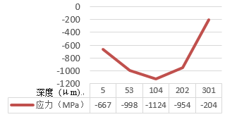
Figure 4. Residual Stress vs. Depth Results
3.5. Fracture surface analysis
3.5.1. Macroscopic examination
The coil spring fractured at 180° along the contact surface between the first coil and the lower spring seat. In this region, the coating had peeled off, and severe corrosion and rust formation were observed. As shown in Figure 5, the failure zone was divided into three distinct regions: Region A (Contact Area with the Spring Seat): Exhibited a metallic luster, indicating long-term dynamic wear at the contact interface. Region B (Crack Propagation Zone): Displayed reddish-brown rust, which spread radially along the wire diameter due to corrosion testing. The propagation direction suggested that the fatigue crack originated from the lower surface of the coil spring. Region C (Final Fracture Zone): Located at the inner and outer sides of the spring coil, this area was shiny and smooth, characteristic of an instantaneous overload fracture. Based on these observations, the primary failure mechanism was identified as stress corrosion fatigue fracture caused by coating damage.
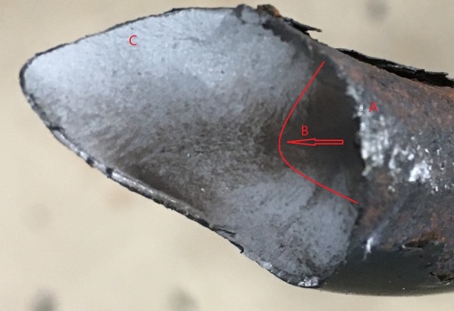
Figure 5. Macroscopic Image of the Fractured Coil Spring
3.5.2. Microscopic fracture analysis
The fracture surface was cleaned to remove rust, and a ZEISS Sigma300 field emission scanning electron microscope (SEM) was used for microscopic analysis:
(1) Crack Initiation Zone: Due to severe rusting, the precise morphology of the crack origin was not clearly visible (Figure 6).
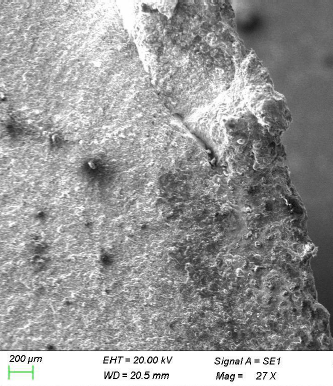
Figure 6. Crack Initiation Zone
(2) Initial Crack Zone: A small amount of intergranular cracking was observed, as indicated by the arrows in Figure 7. This was identified as the original fatigue crack initiation site.
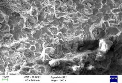
Figure 7. Initial Crack Zone
(3) Crack Propagation Zone: Exhibited ductile dimple features, as shown in Figure 8, indicating that the crack propagation was accompanied by localized plastic deformation. This high-strain zone confirmed that the fracture mechanism was fatigue failure.
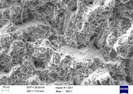
Figure 8. Dimple Features in the Crack Propagation Zone
3.5.3. EDS spectrum analysis
Energy-dispersive spectroscopy (EDS) was performed on the crack initiation area. Spectral analysis of points A and B, as shown in Figure 9, revealed that the primary component was iron oxide (Fe₂O₃). Additionally, the presence of Mg, K, Ca, and Cl elements suggested contamination from multi-component salts commonly used in corrosion testing.
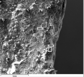
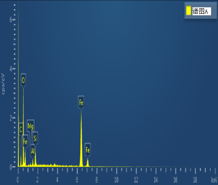
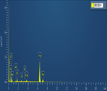
(a) Crack Source Area (b) Spectrum A (c) Spectrum B
Figure 9. EDS Analysis Results
In summary, microscopic analysis revealed the presence of intergranular cracking at the crack initiation site, indicating that during the vehicle accelerated corrosion test, wear between the spring and the damper seat led to coating damage [6]. This exposed the spring to saltwater corrosion, which penetrated the grain boundaries, weakening the intergranular bonding and forming crack initiation sites [5]. Under cyclic loading, these cracks continued to propagate, eventually resulting in fatigue fracture.
4. Force analysis and design optimization of coil spring
4.1. Force analysis
Figure 10 illustrates the force analysis of the MacPherson suspension system, which can be simplified into three forces: W, FC and FA. FA represents the constraint force exerted by the vehicle body on the upper mount of the damper. W is the reaction force from the ground acting on the tire (excluding the unsprung mass). FC is the constraint force from the lower control arm. Based on the planar force equilibrium theory, the magnitude and direction of FA can be calculated using W and FC, as shown in Figure 10(b). FA can be further decomposed into: FAy: the force along the spring’s axis. FAx: the force perpendicular to the shock absorber’s axis, as shown in Figure 10(c).
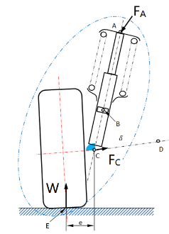
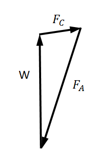
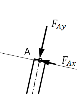
(a) (b) (c)
Figure 10. Force Analysis of the MacPherson Suspension Strut
The force FAx represents the lateral force acting on the shock absorber assembly, which can be further distributed among the lateral forces on the piston rod, acting at the seal and piston, and the lateral force on the coil spring (Flat).
Under static conditions, using the known external force Flat and the spring’s lateral stiffness Klat, the relative displacement between the spring and the spring seat can be estimated using Hooke’s Law, as shown in Equations (1) and (2).
\( ∆x=\frac{{F_{lat}}}{{K_{lat}}} \) (1)
\( {K_{lat}}=\frac{Rξ}{ξ-1+\frac{\frac{1}{λ}}{\frac{1}{2}+\frac{G}{E}}\sqrt[]{(\frac{1}{2}+\frac{G}{E})(\frac{G}{E}+\frac{1-ξ}{ξ})tan{[λξ\sqrt[]{(\frac{1}{2}+\frac{G}{E})(\frac{G}{E}+\frac{1-ξ}{ξ})}]}}} \) (2)
Where:
represents the vertical compression ratio of the spring.
represents the slenderness ratio of the spring.
H₀ is the free height of the spring.
S is the vertical deformation of the spring.
D is the mean coil diameter of the spring.
E is the elastic modulus of the spring material.
G is the shear modulus of the spring material.
4.2. CAE simulation of spring end coil under wheel hop conditions
As the coil spring deforms under varying loads, its helix shape shifts, causing relative motion between the spring and the spring seat. To analyze this behavior, a CAE simulation was conducted using HyperMesh software with an ABAQUS solver. Under full-load conditions, a 3.5G vertical wheel-hop load was applied at the wheel center and tire contact point. The CAE simulation results indicated that at extreme compression, the lower end coil of the spring exhibited potential for dynamic contact and wear against the spring seat [6], as shown in Figure 11.
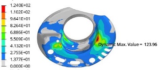
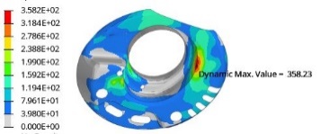
Figure 11. CAE Simulation Results of Spring End Coil Contact
In conclusion, due to lateral load effects, there exists slight relative displacement between the coil spring and the damper spring seat. During wheel hop conditions, the spring compression and rebound induce coil twisting deformation, leading to friction with the spring seat. Additionally, in wheel center hop conditions, the lower end coil dynamically contacts the spring seat, exacerbating potential wear. To mitigate lateral forces on the damper, the MacPherson coil spring in this study adopted: Variable diameter and tapered cross-section design for the spring. Angled support surfaces for the spring seat. Given these observations, the recommended solutions include: Enhancing coating wear resistance. Incorporating rubber pads or protective sleeves.
4.3. Design optimization
The coil spring coating process utilizes electrostatic powder spraying, where the powder is uniformly adsorbed onto the spring surface via electrostatic forces, followed by a curing process.
The designed coating thickness is 60–80 μm.
Solution 1: Adjust the tempering hardness from 52–56 HRC to 52–55 HRC. Increase the coating thickness on the end coil from 60–80 μm to 80–100 μm.
Solution 2: Add a rubber protective sleeve on the spring end coil (or alternatively, place a rubber pad on the lower spring seat). The sleeve would cover approximately 270° of the end coil to prevent direct hard-contact wear.
Solution 3: Implement a dual-layer powder coating: Inner layer: Metal powder-based coating. Total coating thickness: 150–200 μm.
|
|
|
Solution 1 | Solution 2 | Solution 3 |
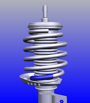
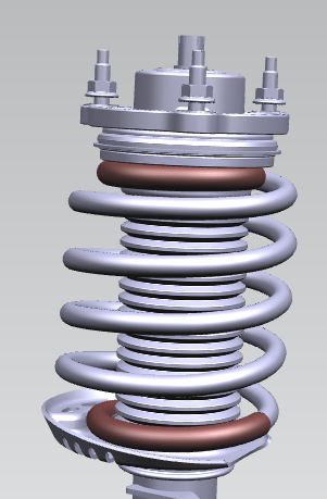
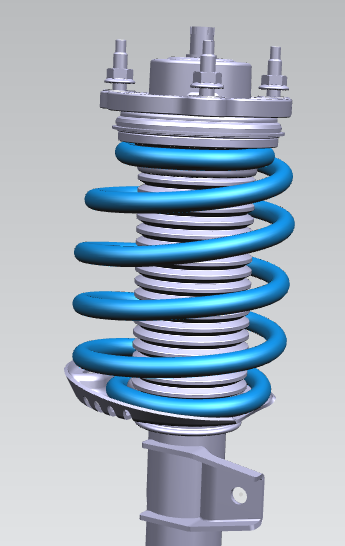
Figure 12. Proposed Design Optimization Solutions
5. Failure reproduction and validation
To validate the optimization proposals outlined in Section 3.3, two sample sets were manufactured for each proposed solution, along with an additional control group using the original design. The samples were subjected to the following tests for comparative analysis, as summarized in Table 2:
Coating wear test: Conducted using a 1/4 vehicle suspension setup, with cyclic loading in the 1–6 Hz range. The test was stopped when the coating damage on the lower end coil exceeded 3 mm.
Salt spray test: Performed according to ASTM B117, with a 20-cycle exposure.
Cyclic fatigue test: Conducted under dry conditions until the spring completed 500,000 cycles or fractured.
Findings from the Tests:
The original design failed to meet the 500,000-cycle fatigue requirement when exposed to intermediate salt spray testing. The fracture occurred at 160° on the lower end coil, with a failure location and mode consistent with full-vehicle corrosion testing. This validated the feasibility of using bench testing for component development and verification.
Effects of design modifications:
Reducing the surface tempering hardness moderately extended the spring’s service life.
Dual-layer powder coating improved coating wear resistance, but localized peeling led to eventual coating failure and substrate corrosion.
Rubber protective sleeves helped mitigate dynamic wear between the coil and the spring seat, but had drawbacks:
Water accumulation within the sleeve could cause corrosion. Debris entrapment between the sleeve and the spring could accelerate coating wear. Enclosed sleeves posed the highest corrosion risk. Open, C-shaped, or perforated sleeves were recommended for better drainage and ventilation.
6. Conclusion
This study analyzed the failure mode of the front coil spring in a full-vehicle corrosion test, covering material properties, hardness, residual stress, microstructure, EDS analysis, and fracture surface examination. By integrating force analysis, it identified a consistent design issue in MacPherson suspension systems, where the shock absorber assembly is subjected to lateral forces. Optimization strategies and bench testing methodologies were proposed to address these issues.
The recommended optimization measures can be implemented in future suspension system development. These solutions provide a systematic approach to reducing coating wear at the spring-seat interface, helping to prevent stress corrosion failure in post-market applications.
Table 2. Comparison of Test Results for Different Design Solutions
No. | Spring Parameters | Wear Test Cycles (Lower End Coil Coating Damage >3mm) | Salt Spray Test | Dry Fatigue Failure Cycles |
Original Design | Hardness: 54–57 HRC Coating Thickness: 60–80 μm | 42,375 cycles / 37,658 cycles | Rust observed at wear location | 426,572 cycles / 430,351 cycles |
Solution 1 | Hardness: 55.5–56 HRC Coating Thickness: 80–100 μm | 46,585 cycles / 47,235 cycles | Rust observed at wear location | 514,844 cycles / 516,920 cycles |
Solution 2 | Hardness: 54–56 HRC Coating Thickness: 60–80 μm | Protective sleeve remained intact after 60,000 cycles | No visible rust | 534,256 cycles / 526,920 cycles |
Solution 3 | Hardness: 54–55 HRC Coating Thickness: 150–200 μm | 54,595 cycles / 55,980 cycles | Rust observed at wear location | 522,350 cycles / 526,257 cycles |
References
[1]. Zhang, Q., Chen, K., Fu, Y., Wang, C., Chen, D., Mei, H., Liu, Z., Dai, Y., & Cong, D. (2021). Study on fracture failure behavior of vehicle suspension coil springs. Equipment Environmental Engineering, 18(8), 100-106.
[2]. Wang, J., Xue, S., Sun, X., & Feng, G. (2020). Optimization study on lateral force of MacPherson suspension dampers based on ADAMS. Automotive Practical Technology(11), 70-71, 76.
[3]. Liang, Y. (2010). Application of stress shot peening in post-treatment of coil springs. Shanghai Automobile(2), 40-41.
[4]. Gao, Y., Yue, K., & Yue, Q. (2023). Study on lateral stiffness of cylindrical coil springs based on computed height correction method. National Defense Traffic Engineering and Technology, 21(6), 15-18, 4.
[5]. Dong, Z., Yang, J., Fan, F., & Wang, L. (2024). Study on stress corrosion performance of high-strength alloy steel. Materials Development and Application, 39(3), 56-60.
[6]. Chao, Y., Zhi, C., & Cai, J. (2018). Analysis and improvement of fracture issues in automotive coil spring end coils. Automotive Practical Technology(11), 55-57.
Cite this article
Li,X.;Zhu,X.;Xu,G.;Cheng,X. (2025). Failure analysis and optimization of coil spring fracture in MacPherson suspension system. Advances in Engineering Innovation,16(1),69-75.
Data availability
The datasets used and/or analyzed during the current study will be available from the authors upon reasonable request.
Disclaimer/Publisher's Note
The statements, opinions and data contained in all publications are solely those of the individual author(s) and contributor(s) and not of EWA Publishing and/or the editor(s). EWA Publishing and/or the editor(s) disclaim responsibility for any injury to people or property resulting from any ideas, methods, instructions or products referred to in the content.
About volume
Journal:Advances in Engineering Innovation
© 2024 by the author(s). Licensee EWA Publishing, Oxford, UK. This article is an open access article distributed under the terms and
conditions of the Creative Commons Attribution (CC BY) license. Authors who
publish this series agree to the following terms:
1. Authors retain copyright and grant the series right of first publication with the work simultaneously licensed under a Creative Commons
Attribution License that allows others to share the work with an acknowledgment of the work's authorship and initial publication in this
series.
2. Authors are able to enter into separate, additional contractual arrangements for the non-exclusive distribution of the series's published
version of the work (e.g., post it to an institutional repository or publish it in a book), with an acknowledgment of its initial
publication in this series.
3. Authors are permitted and encouraged to post their work online (e.g., in institutional repositories or on their website) prior to and
during the submission process, as it can lead to productive exchanges, as well as earlier and greater citation of published work (See
Open access policy for details).
References
[1]. Zhang, Q., Chen, K., Fu, Y., Wang, C., Chen, D., Mei, H., Liu, Z., Dai, Y., & Cong, D. (2021). Study on fracture failure behavior of vehicle suspension coil springs. Equipment Environmental Engineering, 18(8), 100-106.
[2]. Wang, J., Xue, S., Sun, X., & Feng, G. (2020). Optimization study on lateral force of MacPherson suspension dampers based on ADAMS. Automotive Practical Technology(11), 70-71, 76.
[3]. Liang, Y. (2010). Application of stress shot peening in post-treatment of coil springs. Shanghai Automobile(2), 40-41.
[4]. Gao, Y., Yue, K., & Yue, Q. (2023). Study on lateral stiffness of cylindrical coil springs based on computed height correction method. National Defense Traffic Engineering and Technology, 21(6), 15-18, 4.
[5]. Dong, Z., Yang, J., Fan, F., & Wang, L. (2024). Study on stress corrosion performance of high-strength alloy steel. Materials Development and Application, 39(3), 56-60.
[6]. Chao, Y., Zhi, C., & Cai, J. (2018). Analysis and improvement of fracture issues in automotive coil spring end coils. Automotive Practical Technology(11), 55-57.