


1. Introduction
With the accelerated pace of modern urbanization, the importance of living space to human society has become increasingly prominent [1-2]. To better accommodate people's needs in production and daily life, super high-rise buildings have been constructed across China at an unprecedented rate. The promotion of intelligent construction machine steel truss platform technology has effectively addressed the challenges posed by the significant height of super high-rise buildings and the limited construction space. There have been numerous domestic studies on the design and application of intelligent construction machine steel truss platforms. Wang [3] and his colleagues introduced the design and composition of low-position jacking formwork, establishing a comprehensive construction management system, including formwork operation management, maintenance, and process control, to ensure the safety and efficiency of core tube construction. Yu [4] and his team, taking the Tianjin Goldin 117 Tower project as an example, comprehensively elaborated on the construction technology system of a new modular jacking formwork. This system is characterized by its high supporting column height, vertical workflow for the full-process construction of steel plate shear walls, and strong wind resistance. Additionally, the designed jacking formwork’s anti-lateral displacement device demonstrated excellent stability and a high level of safety. As the height of the core tube increases, the wind load on the jacking formwork also rises accordingly. The anti-lateral displacement device designed for this system provides valuable references for improving the jacking formwork’s lateral resistance. Wang [5] and his research team, using the Fuzhou Shimao International Center as a case study, explained the design and composition of the steel platform, the modular layout process, and the relevant node designs. Through static load testing and finite element analysis, they conducted an in-depth study of the mechanical properties of the jacking formwork steel truss platform and proposed improvements for spatially assembled jacking formwork. The design of key jacking formwork systems and the distribution of columns within the core tube section directly impact the convenience and cost-effectiveness of the formwork construction technology. The research findings of Kaiqiang Wang and his team provide valuable design experience for future developments in the field.
After extensive development and application, jacking formwork construction technology has demonstrated high structural safety, economic efficiency, and advanced construction techniques, presenting broad market application prospects [6-7]. However, challenges such as high costs, design complexity, and stress concentration at the connection points between the jacking support system and the steel truss platform remain critical areas for breakthrough and further research [8]. This study takes a super high-rise project in Xi’an as its engineering background and conducts a numerical analysis of the intelligent construction machine steel truss platform during three key phases: construction, jacking, and self-climbing. The analysis results meet the required standards, effectively addressing the issues of slow construction progress and low safety in super high-rise building construction.
The study "Decision Support Model Using the AdaBoost Algorithm to Select Formwork Systems in High-Rise Building Construction" investigates a 335m super high-rise building by monitoring structural deformation during the construction phase and performing numerical simulations. The deformation comparison results indicate that finite element analysis values are largely consistent with field-measured data. Using a validated finite element model, the study further analyzes structural deformations under different real-world construction conditions, including varying concrete construction quality, different construction suspension periods, and different relative humidity (RH) conditions.
The study "Wind-Induced Responses and Dynamic Characteristics of a Super-Tall Building Under a Typhoon Event" conducted structural health monitoring of key components in a public housing project in Singapore. The research suggests that structural health monitoring has the potential to become a core tool in civil engineering. Proper monitoring strategies can assess long-term structural behavior, schedule maintenance, and ensure structural safety. Although civil structure monitoring is a rapidly developing field, there is still a scarcity of literature on the long-term monitoring of complex high-rise structures and related research.
From the research of numerous scholars, it can be observed that there have been extensive studies on the force-bearing performance of integrated steel platform formwork systems for super high-rise buildings, with a primary focus on climbing formwork systems and jacking formwork systems. Numerical simulations and structural monitoring methods have been used for an in-depth analysis of the actual structural forces. However, research on the jacking formwork steel platform system remains relatively limited. Most studies propose improvements and optimizations, mainly by modifying the cross-sectional characteristics of structural components or improving the overall structural form to enhance stiffness and stability.
The study "Research on the Application of Hydraulic Climbing Formwork in the Construction of a High-Rise Hotel Project in Macau" highlights the widespread use of formwork steel platform technology in large-scale complex engineering projects. To better understand the force-bearing state of formwork during construction and ensure high safety standards throughout the process, the study emphasizes the necessity of further investigating the actual force performance of formwork structures under real construction conditions. This is particularly important for ensuring structural safety under lateral forces during the construction of super high-rise buildings.
Other studies, such as "Design and Construction of Large-Stroke Jacking Formwork for a Super High-Rise Core Tube", "Mechanical Performance Research and On-Site Monitoring of Large-Span Steel Grid Structure Integral Jacking Construction", "Monitoring and Stability Analysis of Hydraulic Climbing Formwork in Super High-Rise Buildings", and "Application and Practice of Stress-Strain Monitoring Technology in Large-Scale Steel Truss Hydraulic Lifting Construction", have employed simulation analysis and on-site monitoring techniques to analyze the force-bearing performance of formwork structures during construction. However, most of these studies focus on self-climbing formwork systems and other jacking formwork systems, with limited research specifically addressing the force-bearing performance of jacking formwork steel platform systems using such methods.
Considering the current state of research, some domestic scholars have conducted relevant studies on intelligent construction machine steel truss platforms. However, most of these studies focus on proposing measures to enhance overall stiffness or strength based on research findings. In the force-bearing analysis of intelligent construction machine steel truss platforms, a common issue observed is excessive stress concentration at the connection between the jacking support system and the steel truss system. However, existing studies have not provided direct solutions to this issue, highlighting the need for further research into the force-bearing performance of such formwork systems.
This paper conducts an in-depth analysis of intelligent construction machine steel truss platforms from four perspectives: strength, deformation, structural design, and technology, using real engineering projects as a reference. The findings aim to provide valuable insights for the design of jacking formwork steel truss platforms in similar engineering applications.
2. Project overview
2.1. Core tube design characteristics
The design of the intelligent construction machine steel truss platform system should be closely aligned with the construction sequence and technical requirements of concrete, reinforcement, and formwork engineering. These requirements serve as the core guiding principles for the design process. It is essential to thoroughly understand the specific project overview and the construction characteristics and needs of concrete, reinforcement, and formwork engineering. The design should follow a structured sequence (see Figure 1): first, the main columns and column truss structural layers; second, the steel truss layer; and finally, the steel truss platform layer [9].
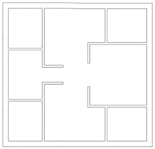
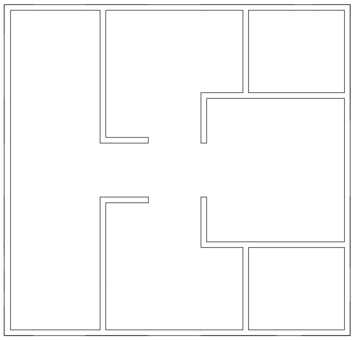
(a) Three-story floor plan (b) Top floor plan
Figure 1. Core tube section change diagram
2.2. Construction requirements
The maximum height of the concrete structure is 267m, posing significant challenges for vertical transportation of materials and personnel, resulting in a high dependence on tower cranes. The efficiency of vertical transportation directly determines the construction speed. Given the tight construction schedule, the reverse planning method based on the total project timeline provided by the owner reveals that the average construction time per core tube floor is only 3 to 5 days [10]. Additionally, at the 32nd floor, wind loads become considerably significant.
Since the tower cranes primarily serve the steel structure construction, the formwork must be self-lifting to reduce reliance on tower cranes. The formwork system should prioritize ease of installation and dismantling [7], while also adapting to variable floor heights and wall thicknesses [11-12]. The system should have strong adaptability to changes in floor plan geometry, requiring minimal or no modifications when encountering variations. Furthermore, it must possess sufficient strength, rigidity, and stability to ensure that the concrete achieves the required appearance and quality after forming [13]. The system should also provide adequate load-bearing platforms for storing various materials and tools, with sufficient stiffness to withstand high-altitude wind loads and other lateral forces encountered during construction. Additionally, it must be capable of providing a working surface spanning four floors, ensuring both technical and scheduling requirements are met [10].
During reinforcement engineering, the formwork system should allow sufficient working space for reinforcement operations and should not obstruct the tying of longitudinal and transverse reinforcement bars [14-15]. When vertical reinforcement bars are extended to a certain height, standard stirrups can only be tied by threading them from the top of the extended vertical reinforcement. Therefore, the truss layer must include a temporary storage platform for stirrups. Furthermore, the hanging brackets should be designed with adequate clearance relative to the shear walls, allowing for positional adjustments as the walls contract over time.
3. Design of the steel truss platform
3.1. Design of steel truss beams
The steel truss consists of two primary trusses and eight secondary trusses. The primary trusses are supported at the top of the main columns, with a beam height of 2500 mm. The standard and non-standard truss sections are connected using double-sided high-strength bolts. The secondary trusses have a beam height of 1700 mm. During the fabrication of the primary trusses, additional vertical web members are added to pre-fabricate the connection nodes between the secondary and primary trusses (see Figure 2). On-site, the secondary trusses are connected to the primary trusses using high-strength bolts [10] (see Figure 3). The web members of both the primary and secondary trusses are connected through welding.
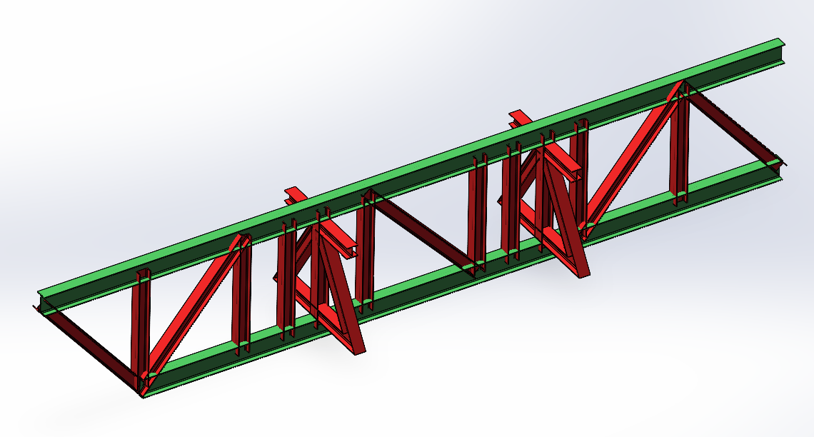
Figure 2. Pre-made primary and secondary truss beam sections
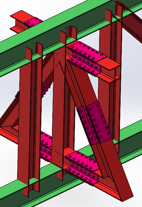
Figure 3. Primary and secondary truss connection node diagram
3.2. Internal design of the steel truss layer
Considering that maintenance personnel frequently need access to the steel truss layer for inspections and repairs, and that workers require space for rebar tying and formwork installation, an internal passage is designed within the truss layer. To create this passage, 3 mm thick corrugated steel plates are welded onto the upper flange of the cantilever beams around the core tube walls, forming a safe and accessible pathway, as shown in the diagrams below (see Figure 4-5).
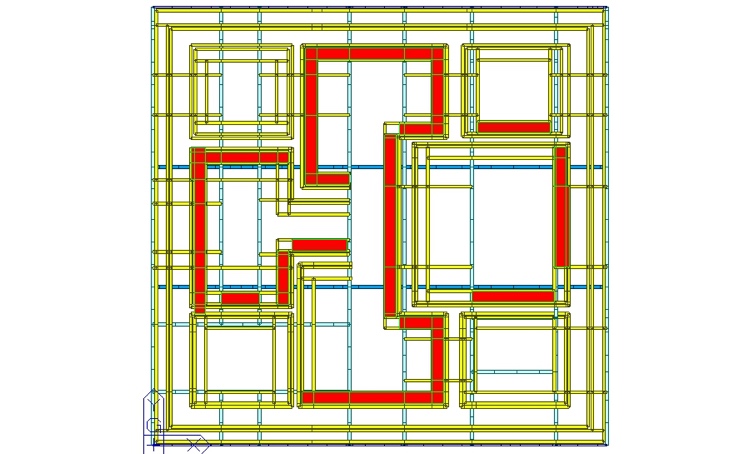
Figure 4. Floor plan of the internal aisle of the steel truss layer (red area)
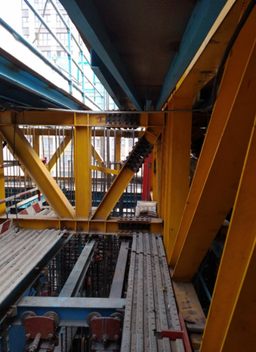
Figure 5. Internal aisle of the steel truss layer
3.3. Top design of the steel truss platform
The upper structure of the steel truss platform consists of 4 mm thick checkered steel plates forming the platform surface, along with auxiliary maintenance facilities [16]. The platform plates, made of checkered steel, are connected to the upper flange of the secondary trusses via channel steel.
Channel steel serves as the load-bearing framework for the platform plates. Its layout primarily considers clearance requirements for openings. In this project, the spacing of the channel steel framework is 500 mm, with some sections reduced to 400 mm near openings, where local reinforcements have been applied, as illustrated below (see Figure 6).
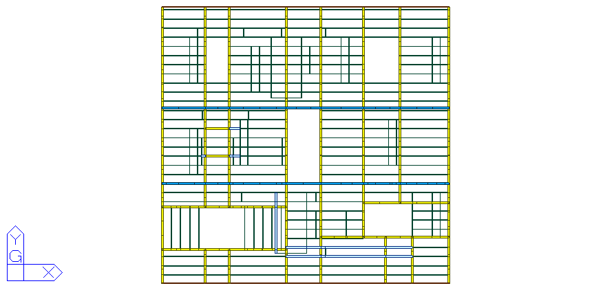
Figure 6. Top design plan of the steel truss platform
4. Numerical analysis of the steel truss platform
4.1. Basic characteristics of the model
The intelligent construction machine steel truss platform consists of two primary trusses, each 2.5 m in height and 28.3 m in length, and 18 secondary trusses of varying lengths, each 1.7 m in height. All components are made of Q345-grade H-shaped steel. The overall model rendering is shown in Figure 7. The cross-section dimensions of the primary truss upper chord members are 350 mm × 200 mm × 8 mm × 12 mm (height × width × web thickness × flange thickness, same format below). All other truss members have a cross-section of 200 mm × 200 mm × 8 mm × 12 mm (see Table 1).
Table 1. Model material specifications
Component | Name | Cross-Section Dimensions |
Primary Truss | Upper Chord | H 350 mm × 200 mm × 8 mm × 12 mm |
Web Member | H 200 mm × 200 mm × 8 mm × 12 mm | |
Secondary Truss | Upper Chord | H 200 mm × 200 mm × 8 mm × 12 mm |
Web Member | H 200 mm × 200 mm × 8 mm × 12 mm | |
Column | Outer Tube | 470 mm × 470 mm × 20 mm |
Inner Tube | 400 mm × 400 mm × 20 mm | |
Column Truss | Upper Chord | 300 mm × 150 mm × 20 mm |
Web Member | O 133 mm × 12 mm | |
Cantilever Beam & Formwork Beam | Cantilever Beam & Formwork Beam | H 250 mm × 175 mm × 7 mm × 11 mm |
Platform Channel Steel | Platform Channel Steel | [ 120 mm × 53 mm × 5.5 mm |
Truss Support | Truss Support | □ 260 mm × 240 mm × 20 mm |
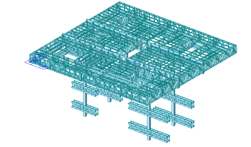
Figure 7. The overall effect drawing of the steel truss platform model of the jacking formwork
4.2. Determination of loads and boundary conditions
According to actual site conditions and relevant codes and standards [17], the structural analysis of the intelligent construction machine steel truss platform primarily considers dead loads, live loads, and wind loads.
4.2.1. Dead loads
Dead loads mainly include the self-weight of the structure, as well as the weight of formwork, cantilever brackets, and the concrete distributor.
• The self-weight of the lightweight steel formwork is applied as a line load of 3.1 kN/m on the formwork cantilever beams.
• The cantilever brackets are calculated with a line load of 4.0 kN/m, and two brackets are set, each bearing 2.0 kN/m.
• The concrete distributor weighs 22.4 t (with a 1.5 safety factor) and is applied as a point load.
• Two storage areas are included, each weighing 3.5 t.
• Three gas cylinder storage boxes are included, each weighing 1.9 t, and are applied as surface loads over their respective placement areas.
4.2.2. Live loads
The steel truss platform is divided into primary stacking areas and secondary stacking areas, as shown in Figure 8.
• The primary stacking areas are used for storing standard-sized reinforcement bars, steel components, toolboxes, electrical cabinets, acetylene-oxygen welding equipment, and fire safety cabinets.
• The secondary stacking areas mainly accommodate smaller steel components or a limited amount of rebar.
• The cantilever bracket walkway panels must account for both worker movement and temporary storage of short-length reinforcement bars.
For ease of calculation and practical application, based on design specifications and relevant standards [17], the loads in the primary and secondary stacking areas are applied as surface loads, considering the uneven distribution of equivalent live loads on the platform. During the jacking and self-climbing phases, all reinforcement materials must be removed from the steel truss platform, and only essential operating personnel are permitted to remain on-site for inspections and operation. The live load design conditions for the platform area are shown in Table 2.
Table 2. Live load distribution
Work Phase | Primary Stacking Area Load (kN/m²) | Secondary Stacking Area Load (kN/m²) | Cantilever Walkway Load (kN/m²) | |
Construction Phase | 7 | 2 | 3 | |
Jacking Phase | 1 | 1 | 1 | |
Self-Climbing Phase | 1 | 1 | 1 | |
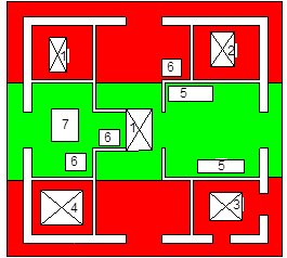
The red area represents the secondary stacking area, and the green area represents the primary stacking area.
Legend:
1. Cutting Opening
2. Stairway Emergency Exit
3. Vertical Elevator
4. Tower Crane Position
5. Storage Area
6. Gas Cylinder Storage Area
7. Concrete Distributor Installation Area
Figure 8. Platform stacking layout drawing
4.2.3. Wind load
This project consists of 58 floors above ground, with a maximum structural height of 268.85 m. The jacking formwork reaches a maximum height of 256 m. The design service life is based on a 10-year return period. The terrain roughness category is classified as Type C, and the wind load is calculated according to the provisions in [18]. The wind load calculation formula is:
\( {w_{k}}={β_{z}}{μ_{s}}{ω_{1}} \) (1)
\( {w_{1}}=1/2ρv_{1}^{2} \) (2)
where:
• \( {w_{k}} \) — Standard wind load value (kN/m²)
• \( {β_{z}} \) — Wind vibration coefficient at height zzz
• \( {μ_{s}} \) — Wind shape coefficient (considering wind shielding effects)
• \( {w_{1}} \) — Calculated wind pressure (kN/m²)
• \( {v_{1}} \) — Calculated wind speed (m/s)
• \( ρ \) — Local air density (for simplification, the standard air density is taken as 1.25 kg/m³)
According to Clause 4.2.5 of reference [18], the wind vibration coefficient may be selected between 1.0 and 1.3. Given that the jacking formwork reaches up to 256 m, the impact of wind load on the structure is significant (see Table 3). For conservative calculations, a wind vibration coefficient of 1.3 is used.
Table 3. Wind load calculation table
Work Phase | Calculated Wind Speed (m/s) | Calculated Wind Pressure (kN/m²) |
Construction Phase | 36.0 | 0.810 |
Jacking Phase | 20.0 | 0.250 |
Self-Climbing Phase | 20.0 | 0.250 |
The cross-section of the steel truss platform is rectangular, as shown in Figure 9. Based on the shape coefficient values provided in [17], the wind shape coefficient \( {μ_{s}} \) is determined as follows:
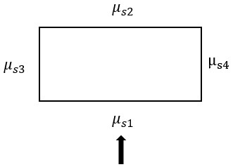
Figure 9. Cross-sectional shape of a steel truss platform
• Windward side: μs1=0.80
• Leeward side: \( {μ_{s2}} \) = -(0.48+0.03 \( \frac{H}{L} \) )=-(0.48+0.03×256/28.2) =-0.752
• Side surfaces are not considered.
By substituting the above variables into the wind load standard value formula, the wind load standard values at different heights are obtained (Table 4):
Table 4. Wind load distribution table
Work Phase | Wind Direction | Wind Load Standard Value (kN/m²) |
Construction Phase | Windward Side | 0.842 |
Leeward Side | 0.792 | |
Jacking Phase | Windward Side | 0.260 |
Leeward Side | 0.240 | |
Self-Climbing Phase | Windward Side | 0.260 |
Leeward Side | 0.240 |
Based on the basic wind pressure for a 10-year return period in the project region and the analysis principles of Midas-Gen software, the wind load standard values are applied in pressure load form to the platform enclosure and cantilever bracket outer panels [19-21]. For conservative calculations, wind permeability of the enclosures is ignored. Wind load on the truss chords and web members is applied in the form of beam element wind pressure (see Figure 10).
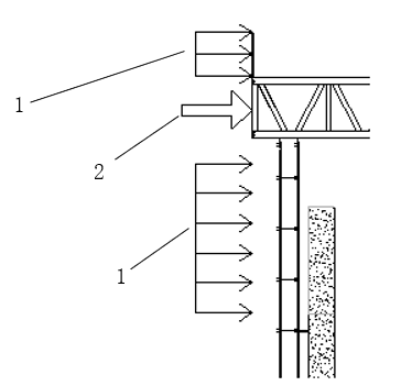
1. Pressure load form, 2. Beam element wind pressure form
Figure 10. Wind load loading assumption
4.2.4. Boundary conditions
During its service life, the steel truss platform undergoes three working phases, with varying boundary conditions at each stage [22].
1) Construction Phase
In the construction phase, the lower chord of the main beam of the steel platform is assumed to be rigidly connected to both the inner and outer columns, as well as the upper chord of the column truss. The ends of the column truss are assumed to be pinned with horizontal constraints, while its connection with the outer column is assumed to be rigid, as shown in Figure 11(a).
2) Jacking Phase
During the jacking phase, the maximum jacking length of the columns is considered as the study condition. The boundary conditions remain the same as those in the construction phase, as shown in Figure 11(a).
3) Self-Climbing Phase
In the self-climbing phase, the top end of the truss support legs is assumed to be rigidly connected to the lower chord of the steel platform main beam, while the bottom end of the truss support legs is assumed to be pinned with horizontal constraints, as shown in Figure 11(b).
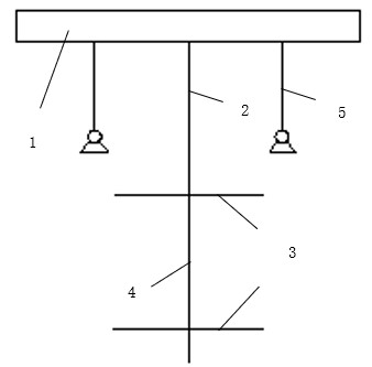
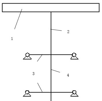
(a) Construction Phase & Jacking Phase (b) Self-Climbing Phase
1. Steel platform, 2. Inner support columns, 3. Main truss, 4. Outer support columns, 5. Truss support legs
Figure 11. Schematic diagram of boundary conditions for each working condition stage
4.3. Load effect combination
In the numerical analysis of the intelligent construction machine steel truss platform [22], the most unfavorable load combination is selected as the design effect value. During its service life, the structure undergoes three phases: the construction phase, jacking phase, and self-climbing phase. Each phase has different structural forms and boundary conditions, necessitating a comprehensive mechanical performance analysis. The ultimate limit state and serviceability limit state of the structure must be examined separately for each phase. Based on reference [18], various load combinations are considered, as detailed in Table 5.
Table 5. Load combination form
Work Phase | Code | Load Combination | Examined State |
Construction Phase | A1 | 1.0 D+1.0 L+1.0 W | Serviceability Limit State |
B2 | 1.3 D+1.5 L+0.6×1.5 W | Ultimate Limit State | |
C3 | 1.3 D+0.7×1.5 L+1.5 W | ||
D4 | 1.35 D+0.7×1.5 L+0.6×1.5 W | ||
Jacking Phase | A1 | 1.0 D+1.0 L+1.0 W | Serviceability Limit State |
B2 | 1.3 D+1.5 L+0.6×1.5 W | Ultimate Limit State | |
C3 | 1.3 D+0.7×1.5 L+1.5 W | ||
D4 | 1.35 D+0.7×1.5 L+0.6×1.5 W | ||
Self-Climbing Phase | A1 | 1.0 D+1.0 L+1.0 W | Serviceability Limit State |
B2 | 1.3 D+1.5 L+0.6×1.5 W | Ultimate Limit State | |
C3 | 1.3 D+0.7×1.5 L+1.5 W | ||
D4 | 1.35 D+0.7×1.5 L+0.6×1.5 W |
4.4. Analysis of the construction phase
4.4.1. Verification of analysis results
To examine the distribution of high-stress components in the structure, the Midas software's de-emphasis function was used to hide elements with a stress ratio lower than 0.65. As shown in Figure 12, components with a stress ratio exceeding 0.65 are mainly concentrated around the connection points between the primary truss and the columns, particularly in the web members and lower chord members. The highest stress ratio occurs in the diagonal web member near the connection node between the southeast column and the primary truss beam, with a maximum value of 0.881. From the stress ratio histogram of the overall structure in Figure 13, it is observed that most structural components have a stress ratio below 0.65, while only a few components exceed 0.65 but remain below 0.9, indicating that the overall structure is relatively safe.
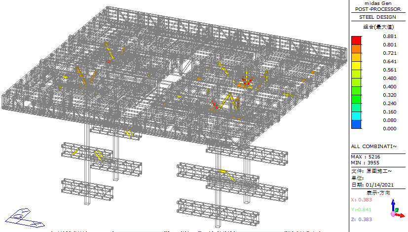
Figure 12. Simplified diagram of overall structural stress ratio during construction
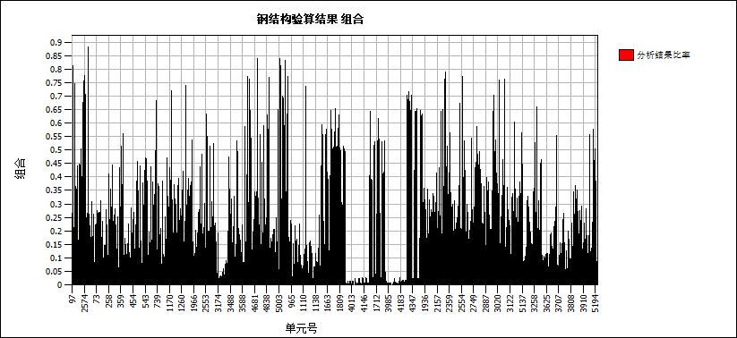
Figure 13. Histogram of overall structural stress ratio during construction
4.4.2. Deformation analysis
During the construction phase, the vertical deformation (Z-direction) of the entire structure was examined. The maximum vertical displacement was found to be 77 mm, occurring at the furthest cantilever end of the secondary truss, as shown in Figure 14. At the connection between the column truss and the column, the maximum vertical displacement recorded was 9 mm, as shown in Figure 15. For horizontal displacement, as shown in Figure 16 and 17, the X-direction displacement is more prominent. The maximum horizontal displacement at the top of the columns is 13 mm.
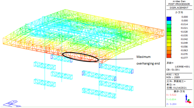
Figure 14. Schematic diagram of the overall vertical (Z-direction) displacement of the structure during the construction phase
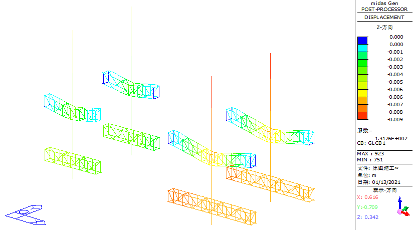
Figure 15. Schematic diagram of vertical (Z-direction) displacement of column truss during construction
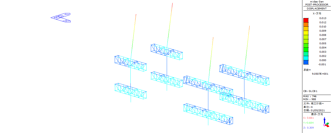
Figure 16. XZ plane displacement diagram of jacking system structure during construction

Figure 17. Schematic diagram of the XY plane displacement of the jacking system structure during the construction phase
During on-site investigations, it was observed that in the construction phase, due to rebar tying operations, steel reinforcement bundles were unevenly stacked on the platform top. To ensure structural safety under uneven loading conditions, a numerical analysis was conducted to verify the structural reliability under these conditions.
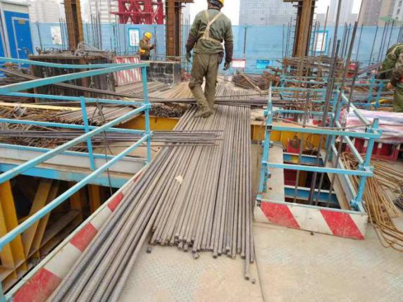
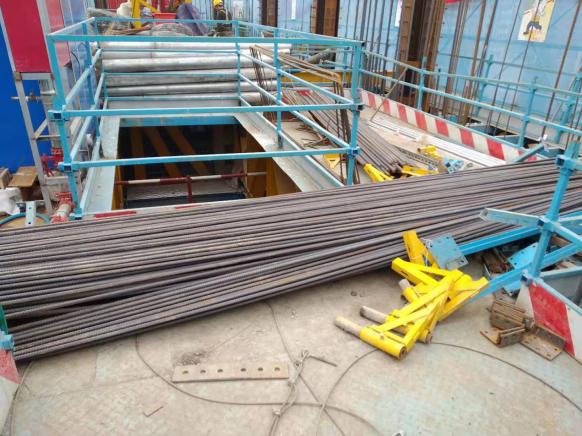
Figure 18. The situation of stacking steel bars at the edge of the opening
According to the functional zoning of the platform, 17 steel stacking surfaces were selected at the platform's top openings and edge areas. Each stacking surface is rectangular, with dimensions of 4.5 m (length) × 0.9 m (width), and can hold up to 3 t of steel reinforcement. The spatial distribution of the stacking areas is illustrated in Figure 19.
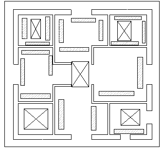
Figure 19. Schematic diagram of the distribution of steel bars
To examine the distribution of high-stress components in the structure, the Midas software's de-emphasis function was again used to hide elements with a stress ratio lower than 0.65. As shown in Figure 20, elements with stress ratios exceeding 0.65 are mainly concentrated in the web members and lower chord members near the connection points between the primary truss and the columns, as well as in the chord and web members at the connection between the column and column truss. The maximum stress ratio is observed in the diagonal web member near the connection point between the column and the primary truss, with a peak value of 0.931. From Figure 21, which presents the histogram of the overall structural stress ratio, it is evident that most structural components have a stress ratio below 0.65, with a small number of components exceeding 0.65 but remaining below 0.95, indicating that the overall structure remains relatively safe.
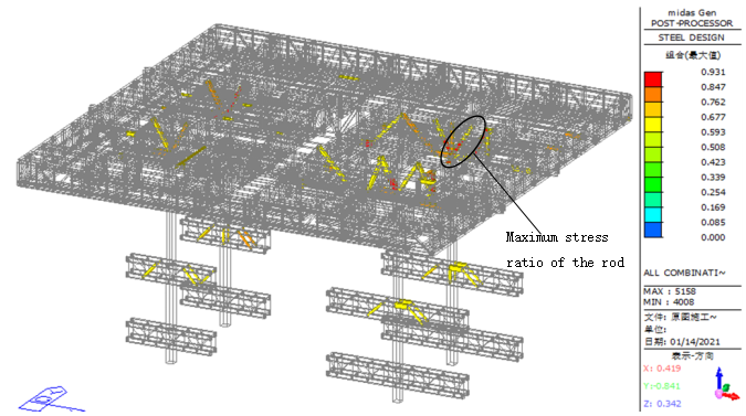
Figure 20. Simplified diagram of the overall stress ratio of the structure after adding steel reinforcement during the construction phase
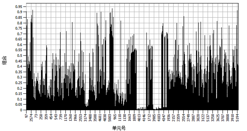
Figure 21. Histogram of the overall stress ratio of the structure after adding steel reinforcement during the construction phase
When steel reinforcement is loaded onto weak areas such as edge openings of the steel truss platform, the maximum vertical displacement occurs at the cantilever end of the secondary truss on the southeast side, reaching 81 mm, as shown in Figure 22. At the connection between the column truss and the column, the maximum vertical displacement remains 9 mm, as shown in Figure 23. For horizontal displacement, the maximum X-direction displacement at the column top is 14 mm, as shown in Figure 24 and 25.
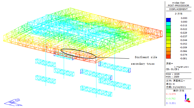
Figure 22. Schematic diagram of the vertical displacement of the structure after adding steel reinforcement during the construction phase
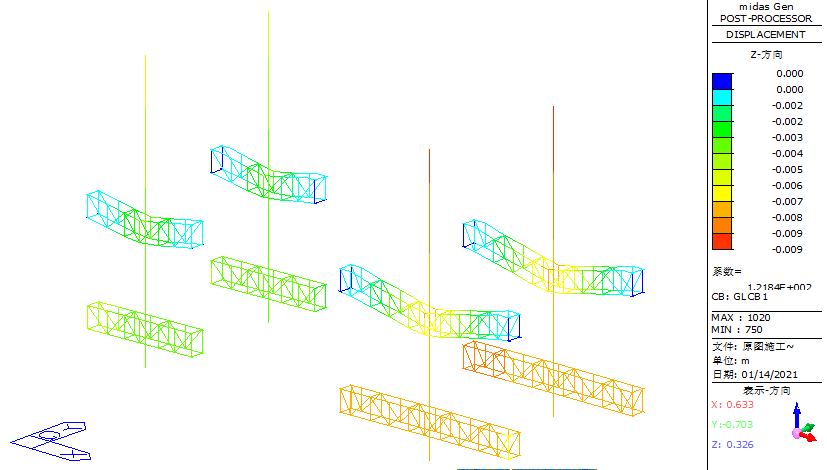
Figure 23. Schematic diagram of the vertical displacement of the jacking system after adding steel reinforcement during the construction phase
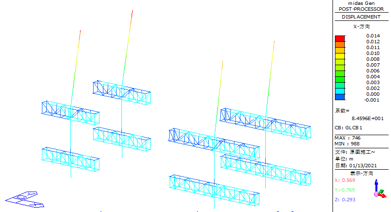
Figure 24. Schematic diagram of XZ plane displacement of jacking system structure after adding steel reinforcement during construction
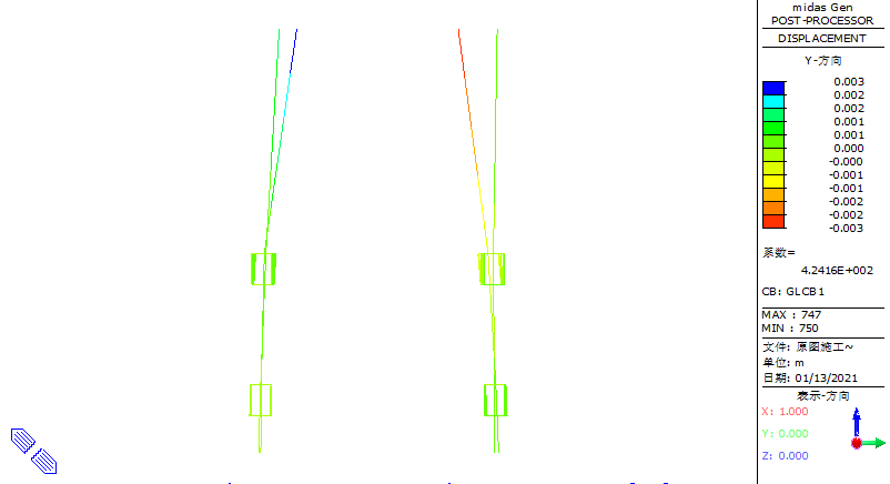
Figure 25. Schematic diagram of the XY plane displacement of the jacking system structure after adding steel reinforcement during the construction phase
4.5. Analysis of the jacking phase
4.5.1. Verification of analysis results
Using the same method as previously described, components with a stress ratio below 0.65 were hidden to highlight high-stress regions, as shown in Figure 26. During the jacking phase, components with stress ratios exceeding 0.65 are primarily concentrated near the diagonal web members and chord members at the connection points between the columns and the primary trusses. The maximum stress ratio recorded is 0.773. From the histogram of the overall structural stress ratio in Figure 27, it is observed that over 90% of the components in the steel truss platform have a stress ratio below 0.65. A small number of components exceed 0.8 but do not exceed 0.85, indicating a high level of structural safety.
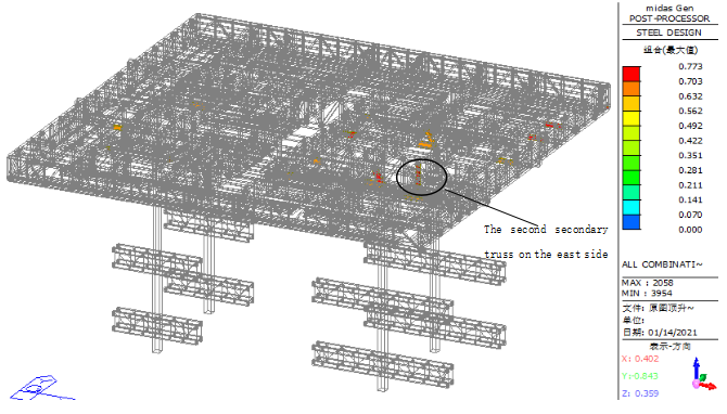
Figure 26. Simplified diagram of the overall stress ratio of the structure during the jacking phase
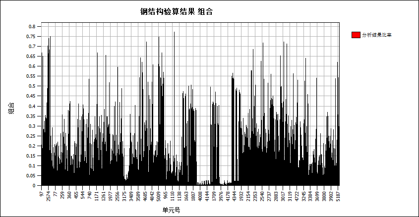
Figure 27. Histogram of the overall stress ratio of the structure during the jacking phase
4.5.2. Deformation analysis
During the jacking phase, the maximum vertical displacement of the steel truss platform is recorded as 67 mm, occurring at the mid-span region of the edge-sealing truss on the south side, as shown in Figure 28.
The maximum vertical displacement at the connection between the column truss and the column is 6 mm, occurring at the southeast column-to-column truss connection, as shown in Figure 29.
For horizontal displacement, as shown in Figure 30 and 31, the X-direction displacement is prominent, with the maximum horizontal displacement at the top of the columns recorded as 12 mm.
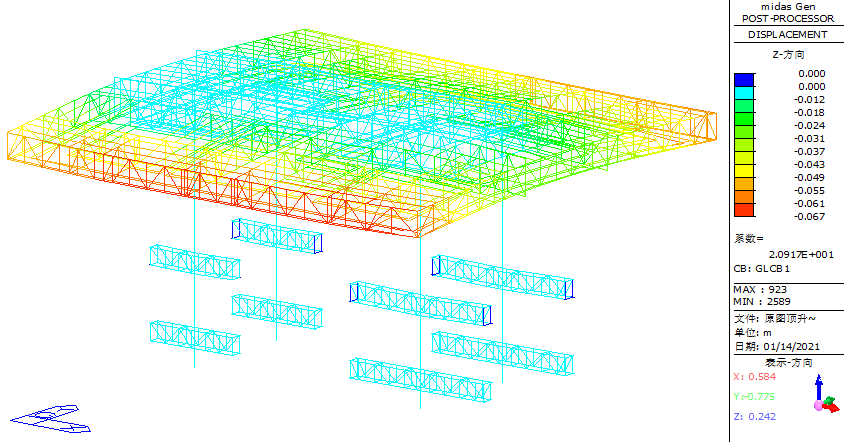
Figure 28. Vertical displacement diagram of the structure during the jacking phase
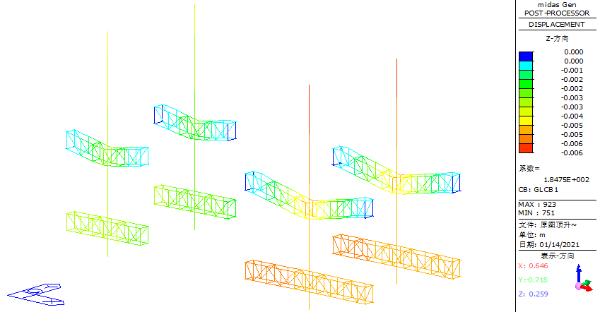
Figure 29. Schematic diagram of the vertical displacement of the structure at the jacking stage
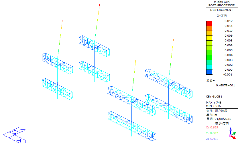
Figure 30. XZ plane displacement diagram of the jacking system structure in the jacking stage
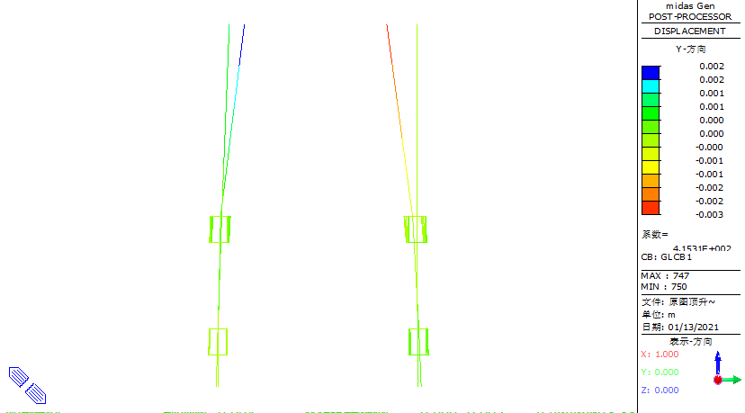
Figure 31. Schematic diagram of the XY plane displacement of the structure during the jacking phase
4.6. Analysis of the self-climbing phase
4.6.1. Verification of analysis results
As shown in Figure 32, the maximum stress ratio in the steel truss platform (considering strength verification, shear verification, and stability verification) is 0.774, occurring at the connection between the formwork beam and the secondary truss. Additionally, during the self-climbing phase, it is observed that the stress ratios of the components near the connection nodes between the columns and the lower chord members of the primary trusses are lower than 0.65, compared to the construction and jacking phases. From the histogram of the overall structural stress ratio in Figure 33, it is evident that most structural components have a stress ratio below 0.5, with only a few components exceeding 0.5 but remaining below 0.8. This indicates a large safety margin for the structure.
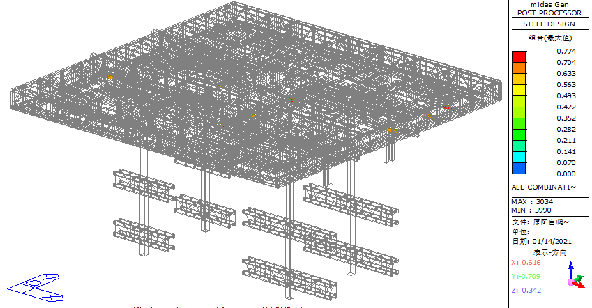
Figure 32. Simplified diagram of the overall stress ratio of the structure during the self-climbing phase
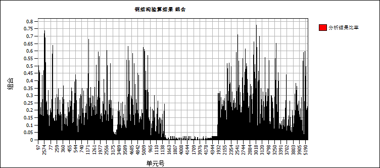
Figure 33. Histogram of the overall stress ratio of the structure in the self-climbing phase
4.6.2. Deformation analysis
During the self-climbing phase, the vertical deformation (Z-direction) of the structure was analyzed. The maximum vertical displacement recorded is 57 mm, occurring at the furthest cantilever end of the secondary truss, as shown in Figure 34.
For horizontal displacement, it is observed that Y-direction displacement is prominent, as shown in Figure 35 and 36. The maximum horizontal displacement at the base of the column is 38 mm.
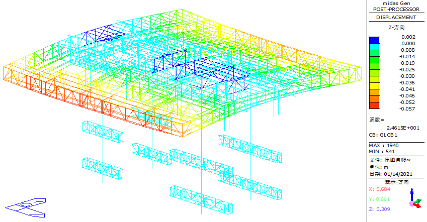
Figure 34. Schematic diagram of the overall vertical (Z-direction) displacement of the structure during the self-climbing phase
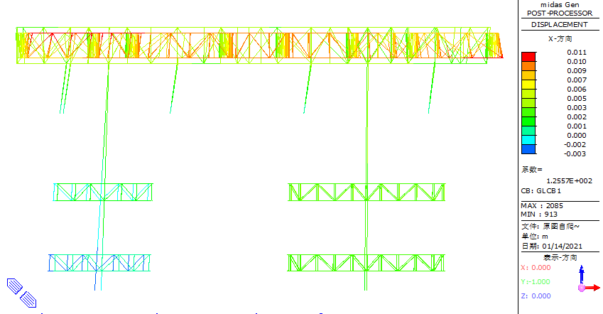
Figure 35. Schematic diagram of the XZ plane displacement of the jacking system structure in the self-climbing phase
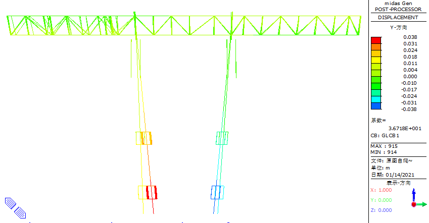
Figure 36. Schematic diagram of the XY plane displacement of the jacking system structure in the self-climbing phase
5. Conclusion
(1) Strength Analysis: During the construction phase, the maximum stress ratio of the components in the steel truss platform was 0.931, while most components had a stress ratio below 0.65, meeting the design standards for steel structures. Components with stress ratios exceeding 0.65 were primarily located in the web members of the primary truss and column truss web members. To improve axial tension and axial compression bearing capacity, the cross-sectional area of these high-stress web members should be increased.
(2) Deformation Analysis: According to the numerical analysis results, the maximum deformation phase of the intelligent construction machine steel truss platform occurs during the construction phase. The largest vertical displacement was recorded at the furthest cantilever end of the secondary truss beam on the southeast side, with a maximum vertical displacement of 81 mm. At the cantilever root, the vertical displacement was 27 mm, resulting in a cantilever deflection value of:
81mm-27mm=54mm<2L/250=9937mm×2/250=79.496mm
The mid-span vertical displacement of the primary truss was 19 mm, while the column top vertical displacement was 7 mm, leading to a deflection value of:
19mm-7mm=12 mm<15498mm/400=38.745mm
The maximum horizontal displacement at the top of the column was 13 mm, satisfying the condition:
3mm<7200 mm/150=48 mm
These values confirm that the structure complies with steel structure design standards.
(3) Structural Configuration: Under different working conditions, due to multiple vertical connection nodes in the trusses, significant shear interactions occur between trusses and between trusses and columns, resulting in high-stress ratios at connection nodes. It is recommended to enhance the strength of components at primary and secondary truss connections and at truss beam-to-column joints. Specifically, the chord or web members at the primary-secondary truss connections should be made of high-strength steel or have an increased cross-sectional area. Additionally, connecting members should be added at truss beam-to-column joints to reduce the shear effect of columns on truss chords.
(4) Technical Considerations: From the self-climbing phase analysis, if all four main columns climb simultaneously during the service period of the jacking formwork steel truss platform, the maximum stress ratio in the web members near the joints of the truss legs and the lower chord of the secondary truss exceeds 0.774, and the maximum horizontal displacement at the base of the main columns reaches 38 mm. After self-climbing operations, it is necessary to immediately adjust the position of the main columns. Therefore, simultaneous self-climbing of all four main columns is not allowed during the service period of the jacking formwork, as it may cause stress concentration issues in the steel truss platform.
Based on the analysis in these four key aspects, it is concluded that the intelligent construction machine steel truss platform meets the design standards for steel structure strength and stiffness, demonstrating overall safety and reliability. This study provides valuable insights for similar engineering projects. However, due to high stress and deformation observed at the primary-secondary truss connections and at truss beam-to-column joints, further improvements in structural configuration and technical aspects are necessary to optimize the intelligent construction machine steel truss platform.
Funding project
Shaanxi Provincial Key Research and Development Program (2023JBGS-17)
References
[1]. Dong, S. (2010). The development and prospect of China's spatial structure. Journal of Building Structures, 31(6), 38-51.
[2]. Saito, M., Li, X., Xu, H., et al. (2019). The development and prospect of spatial structure-the past, present and future of spatial structure design. World Architecture(3), 127.
[3]. Wang, J., Zhong, X., Zhao, J., et al. (2016). Application of low-position jacking formwork system for super high-rise buildings. Building Technology, 47(6), 537-540.
[4]. Yu, D., Hou, Y., Ai, X., et al. (2015). The key technology of the design of the new anti-side displacement modular low-rise steel platform formwork system of Tianjin Gaoyin 117 Building. Construction Technology, 44(23), 1-6.
[5]. Wang, K., Guo, Y., Wu, Y., et al. (2012). Design and test research of prefabricated space steel truss platform for modular low-position steel platform formwork system. Construction Technology, 41(15), 1-6+21.
[6]. Karshenas, S. (1997). Strength variability of conventional slab formwork systems. Journal of Construction Engineering and Management, 123(3), 324-330.
[7]. Sai, G. M., & Aravindan, A. (2020). A comparative study on newly emerging type of formwork systems with conventional type of form work systems. Materials Today: Proceedings, 33(prepublish), 736-740.
[8]. Xiao, C., Wang, C., & Huang, X. (2013). Development and prospect of research on high-rise building structure of China Academy of Building Research. Building Science, 29(11), 11-21.
[9]. Zeng, F., Mu, Z., & Zhang, J. (2016). Design and construction of a large-stroke jacking formwork for a super high-rise core tube. Steel Structure, 31(10), 84-87+92.
[10]. Zeng, F., Mu, Z., & Zhang, J. (2017). Construction technology of large-stroke jacking formwork for the core tube of a super high-rise building. Steel Structure, 32(9), 110-114+46.
[11]. Shaffer, M. (2017). Developing robotic formwork: enhancing formwork mobility and variability through mechanization. Construction Robotics, 1(1-4), 77-83.
[12]. Shin, Y., Kim, D. W., Yang, S. W., et al. (2008). Decision support model using the AdaBoost algorithm to select formwork systems in high-rise building construction. In Proceeding of the 25th International Symposium on Automation and Robotics in Construction (pp. 26-29).
[13]. Shin, Y., Kim, T., Cho, H., et al. (2012). A formwork method selection model based on boosted decision trees in tall building construction. Automation in Construction, 23, 47-54.
[14]. Xu, L. S. (2019). Citic Tower Construction Key Technology. International Journal of High-Rise Buildings, 8(3), 185-192.
[15]. Liu, P., Cheng, Y., & Zhu, Y. S. (2016). The structural design of "China Zun" Tower, Beijing. International Journal of High-Rise Buildings, 5(3), 213-220.
[16]. Bai, X., Ma, H., Yao, C., et al. (2013). Design and modal analysis of jacking formwork system for super high-rise buildings. Industrial Construction, 43(5), 14-17+51.
[17]. Ministry of Housing and Urban-Rural Development of the People's Republic of China. (2012). Load code for the design of building structures. GB 50009-2012. [S]. Beijing: China Construction Industry Press.
[18]. Ministry of Housing and Urban-Rural Development of the People's Republic of China. (2019). Technical standards for integral climbing steel platform formwork. JGJ 459-2019. [S]. Beijing: China Construction Industry Press.
[19]. Irwin, P. A. (2009). Wind engineering challenges of the new generation of super-tall buildings. Journal of Wind Engineering & Industrial Aerodynamics, 97(7-8), 328-334.
[20]. Li, Q., Zhi, L., & Duan, Y. (2010). Full-scale measurements and analysis of wind induced response of Taipei 101 Tower. Journal of Building Structures, 31(3), 24-31.
[21]. Li, Y., Fu, Y., & Li, C. (2018). Study on wind resistance performance of super high-rise building structure. Journal of Building Science and Engineering, 35(2), 63-70.
[22]. Li, Q., Zhou, K., He, Y., et al. (2016). Construction monitoring and simulation study on Ping’an Financial Center in Shenzhen. Journal of Architecture and Civil Engineering, 33(3), 9-18.
Cite this article
Zhang,Z.;Zeng,F.;Liu,J.;Guo,H.;Niu,Y.;Du,G.;Liu,X. (2025). Design and force analysis of steel truss of intelligent construction machine for super high-rise buildings. Advances in Engineering Innovation,16(2),1-24.
Data availability
The datasets used and/or analyzed during the current study will be available from the authors upon reasonable request.
Disclaimer/Publisher's Note
The statements, opinions and data contained in all publications are solely those of the individual author(s) and contributor(s) and not of EWA Publishing and/or the editor(s). EWA Publishing and/or the editor(s) disclaim responsibility for any injury to people or property resulting from any ideas, methods, instructions or products referred to in the content.
About volume
Journal:Advances in Engineering Innovation
© 2024 by the author(s). Licensee EWA Publishing, Oxford, UK. This article is an open access article distributed under the terms and
conditions of the Creative Commons Attribution (CC BY) license. Authors who
publish this series agree to the following terms:
1. Authors retain copyright and grant the series right of first publication with the work simultaneously licensed under a Creative Commons
Attribution License that allows others to share the work with an acknowledgment of the work's authorship and initial publication in this
series.
2. Authors are able to enter into separate, additional contractual arrangements for the non-exclusive distribution of the series's published
version of the work (e.g., post it to an institutional repository or publish it in a book), with an acknowledgment of its initial
publication in this series.
3. Authors are permitted and encouraged to post their work online (e.g., in institutional repositories or on their website) prior to and
during the submission process, as it can lead to productive exchanges, as well as earlier and greater citation of published work (See
Open access policy for details).
References
[1]. Dong, S. (2010). The development and prospect of China's spatial structure. Journal of Building Structures, 31(6), 38-51.
[2]. Saito, M., Li, X., Xu, H., et al. (2019). The development and prospect of spatial structure-the past, present and future of spatial structure design. World Architecture(3), 127.
[3]. Wang, J., Zhong, X., Zhao, J., et al. (2016). Application of low-position jacking formwork system for super high-rise buildings. Building Technology, 47(6), 537-540.
[4]. Yu, D., Hou, Y., Ai, X., et al. (2015). The key technology of the design of the new anti-side displacement modular low-rise steel platform formwork system of Tianjin Gaoyin 117 Building. Construction Technology, 44(23), 1-6.
[5]. Wang, K., Guo, Y., Wu, Y., et al. (2012). Design and test research of prefabricated space steel truss platform for modular low-position steel platform formwork system. Construction Technology, 41(15), 1-6+21.
[6]. Karshenas, S. (1997). Strength variability of conventional slab formwork systems. Journal of Construction Engineering and Management, 123(3), 324-330.
[7]. Sai, G. M., & Aravindan, A. (2020). A comparative study on newly emerging type of formwork systems with conventional type of form work systems. Materials Today: Proceedings, 33(prepublish), 736-740.
[8]. Xiao, C., Wang, C., & Huang, X. (2013). Development and prospect of research on high-rise building structure of China Academy of Building Research. Building Science, 29(11), 11-21.
[9]. Zeng, F., Mu, Z., & Zhang, J. (2016). Design and construction of a large-stroke jacking formwork for a super high-rise core tube. Steel Structure, 31(10), 84-87+92.
[10]. Zeng, F., Mu, Z., & Zhang, J. (2017). Construction technology of large-stroke jacking formwork for the core tube of a super high-rise building. Steel Structure, 32(9), 110-114+46.
[11]. Shaffer, M. (2017). Developing robotic formwork: enhancing formwork mobility and variability through mechanization. Construction Robotics, 1(1-4), 77-83.
[12]. Shin, Y., Kim, D. W., Yang, S. W., et al. (2008). Decision support model using the AdaBoost algorithm to select formwork systems in high-rise building construction. In Proceeding of the 25th International Symposium on Automation and Robotics in Construction (pp. 26-29).
[13]. Shin, Y., Kim, T., Cho, H., et al. (2012). A formwork method selection model based on boosted decision trees in tall building construction. Automation in Construction, 23, 47-54.
[14]. Xu, L. S. (2019). Citic Tower Construction Key Technology. International Journal of High-Rise Buildings, 8(3), 185-192.
[15]. Liu, P., Cheng, Y., & Zhu, Y. S. (2016). The structural design of "China Zun" Tower, Beijing. International Journal of High-Rise Buildings, 5(3), 213-220.
[16]. Bai, X., Ma, H., Yao, C., et al. (2013). Design and modal analysis of jacking formwork system for super high-rise buildings. Industrial Construction, 43(5), 14-17+51.
[17]. Ministry of Housing and Urban-Rural Development of the People's Republic of China. (2012). Load code for the design of building structures. GB 50009-2012. [S]. Beijing: China Construction Industry Press.
[18]. Ministry of Housing and Urban-Rural Development of the People's Republic of China. (2019). Technical standards for integral climbing steel platform formwork. JGJ 459-2019. [S]. Beijing: China Construction Industry Press.
[19]. Irwin, P. A. (2009). Wind engineering challenges of the new generation of super-tall buildings. Journal of Wind Engineering & Industrial Aerodynamics, 97(7-8), 328-334.
[20]. Li, Q., Zhi, L., & Duan, Y. (2010). Full-scale measurements and analysis of wind induced response of Taipei 101 Tower. Journal of Building Structures, 31(3), 24-31.
[21]. Li, Y., Fu, Y., & Li, C. (2018). Study on wind resistance performance of super high-rise building structure. Journal of Building Science and Engineering, 35(2), 63-70.
[22]. Li, Q., Zhou, K., He, Y., et al. (2016). Construction monitoring and simulation study on Ping’an Financial Center in Shenzhen. Journal of Architecture and Civil Engineering, 33(3), 9-18.