


1 Introduction
In today’s rapidly advancing technological landscape, metal materials hold a crucial position across various fields. From aircraft structures in aerospace to high-rise buildings and bridges in civil engineering, from automotive components to internal parts of electronic devices, the performance and reliability of metals directly impact the functionality and safety of entire systems [1]. In these applications, metal workpieces experience strain under various loads. Accurate measurement of metal strain is essential for ensuring structural safety and the proper functioning of equipment. In aerospace, critical components such as aircraft wings and engines face complex stress environments during flight, where understanding their strain behavior helps prevent structural fatigue and failure, thereby enhancing flight safety [2]. In civil engineering, strain monitoring of metal structures in bridges and buildings enables the timely detection of potential safety risks, such as stress concentration or deformation caused by prolonged loads, facilitating maintenance and reinforcement measures. In automotive manufacturing, monitoring the strain on parts can optimize design and manufacturing processes, improving product quality and reliability and reducing failures caused by strain [3]. In electronics, the strain on metal components can affect circuit performance, and accurate strain measurement ensures the proper operation of electronic devices.
Given the importance of metal strain measurement, this paper focuses on five common types of sensors used for measuring metal strain: resistance sensors, fiber optic sensors, piezoelectric sensors, Hall sensors, and capacitive sensors. Each of these sensors operates based on different physical principles and has distinct working mechanisms and application advantages. An in-depth exploration of their working principles, practical applications, advantages and disadvantages, and future development trends will provide a comprehensive reference for research and practice in related fields. This can contribute to further improving the accuracy and reliability of metal strain measurement, advancing relevant industries, and better meeting the demands for metal strain measurement across various sectors.
2 Main types of sensors and their working principles
2.1 Resistance sensors
Resistance sensors are used to measure the slight deformations (strains) generated in a material under external loads. They consist of a very thin conductor (such as metal foil) attached to the object being measured. These sensors operate based on two principles. The first relies on deformation: when an external force is applied, the conductor deforms along with the object, changing the conductor's resistance. The second principle relies on the change in resistivity under compression; when the conductor is compressed, its resistivity changes, and monitoring this resistance change can indicate the strain. Based on the basic resistance formula 1.
\( R=\frac{ρL}{A}\ \ \ (1) \)
where \( R \) is resistance, \( ρ \) represents the material’s resistivity.
L: the length of the resistance element
A: cross-sectional area
2.2 Fiber optic sensors
Fiber optic stress sensors use optical fibers as sensitive elements, measuring stress by detecting changes in the light signal within the fiber. The sensor mainly consists of a light source, optical fiber, detector, and signal processing unit.
The principle is as equation 2.
\( Δλ=λ×k×ε\ \ \ (2) \)
Where \( Δλ \) represents the change in the wavelength of light within the fiber, \( λ \) is the initial wavelength, \( k \) is the optical strain coefficient of the fiber, and \( ε \) is the strain caused by the applied stress.
When the optical fiber is subjected to stress, its geometric shape and refractive index change, altering the propagation characteristics of light within it. By detecting the wavelength shift, the strain caused by the stress can be calculated, which in turn allows the determination of the stress magnitude [4].
2.3 Piezoelectric sensors
Piezoelectric stress sensors are sensors based on the piezoelectric effect, used to measure force and other non-electrical physical quantities that can be converted into force, such as acceleration and pressure.
The working principle of piezoelectric stress sensors primarily relies on the piezoelectric effect shown as equation 3.
\( Q=d×F\ \ \ (3) \)
Where \( Q \) represents the amount of generated electric charge, 𝑑 is the piezoelectric constant, and \( F \) is the force applied to the piezoelectric material.
The change in voltage \( ΔU \) can be expressed as equation 4.
\( ΔU=\frac{Q}{C}=\frac{dF}{C}\ \ \ (4) \)
Where \( C \) is the capacitance of the capacitor. By measuring this voltage change, the magnitude of the external force applied to the piezoelectric material can be indirectly determined [5].
2.4 Hall sensors
When a current \( I \) flows through a Hall element (typically a thin semiconductor plate) and a magnetic field \( B \) is present perpendicular to the current direction, the Hall effect generates a Hall voltage \( V \) on the other two sides of the semiconductor plate as shown in equation 5.
\( V=K×I×B\ \ \ (5) \)
Where \( I \) is the current through the element, \( B \) is the magnetic flux density perpendicular to the Hall element, and \( K \) represents the sensitivity coefficient of the Hall element. According to the Biot-Savart law, the magnetic flux density produced by a current-carrying straight wire is given by equation 6.
\( B=\frac{μI}{2πr}\ \ \ (6) \)
Where \( μ \) is the permeability of free space, \( I \) is the current in the wire, and \( r \) is the distance from the measurement point to the wire. When a metal material undergoes stress, its internal permeability changes, which in turn alters the magnetic flux density and affects the Hall voltage [6].
2.5 Capacitive sensors
A capacitive strain sensor typically consists of two parallel metal plates with an insulating dielectric material between them. When the sensor undergoes strain due to external force, changes occur in the distance between the plates, the relative area of the plates, or the dielectric constant of the insulating material, leading to a change in capacitance as equation 7.
\( C=\frac{εA}{d}\ \ \ (7) \)
Where \( C \) is the capacitance, \( ε \) is the dielectric constant of the insulating material, \( A \) is the relative area of the plates, and \( d \) is the distance between the plates. When strain is applied to the sensor’s location on the workpiece, assuming an initial distance \( d_{0} \) and a changed distance \( d_{1}=d_{0}+Δd \) , the change in capacitance \( ΔC \) can be derived by differentiating the capacitance formula: \( \frac{δC}{δd}=-\frac{εA}{d^{2}} \) , thus \( ΔC≈-\frac{εA}{d_{0}^{2}}Δd \) . This relationship between the capacitance change and the distance between plates allows for determining the stress state of the metal based on the change in capacitance.
3 Current applications
In an application study conducted by Zhejiang Geely Automobile Research Institute Co., Ltd., resistance strain gauges were used to monitor the door-opening process during side collisions. Focusing on the door lock system of a particular vehicle model, an elastic steel plate was attached to the flat side of the lock body and secured with hot melt adhesive, while the other end was aligned tangentially with the lock body arm. This setup ensured that the movement of the elastic steel plate was synchronized with the lock arm. A resistance strain gauge was installed on the elastic steel plate. The horizontal displacement of the lock arm in the door lock system was calibrated by collecting four measurements at regular intervals. A linear fitting formula was then derived, which was used to convert the measurements into a displacement-time curve for the lock arm in a left rear door side impact test.
In a study by the Department of Robotics Engineering at Karunya Institute of Technology and Sciences in India, researchers used strain gauges for automatic strain measurement on steel beams. The strain gauges were fixed to the surface of cantilever low-carbon steel beams, and thin back leads were used to connect the strain gauge to the test sample, allowing direct transfer of strain from the sample to the strain gauge. The strain gauge responded to the strain by displaying a linear change in resistance [7].
In the health monitoring of gantry cranes conducted by the Zhuhai Testing Institute of Guangdong Special Equipment Inspection Research Institute, strain gauges were attached to the surface of cantilever low-carbon steel beams. The cross-section of the steel beam was symmetric, with strain gauges fixed at the top and bottom of the beam. The strain gauges were connected to test samples via thin back leads, allowing the strain obtained from the sample to be directly transferred to the strain gauge. The strain gauge then responded with a linear change in resistance, helping detect damage in the steel beam.
At the Chuzhou Special Equipment Supervision and Inspection Center, strain gauges were installed at specific locations on bridge crane metal structures to test and analyze stress. The collected data was aggregated and analyzed to understand the force conditions on the crane arm.
In a study at Dalian University of Technology on the impact of stress levels and localized corrosion on strain transfer between rebar and distributed fiber optic sensors (DFOS), commercially available single-mode fiber was selected as the DFOS. The DFOS was embedded along the longitudinal ribs of hot-rolled ribbed rebar within a pre-cut groove and fixed with epoxy resin. The rebar with the DFOS was then cast into a concrete slab. During the experiment, an optical interrogator recorded the strain distribution of the DFOS under different load levels.
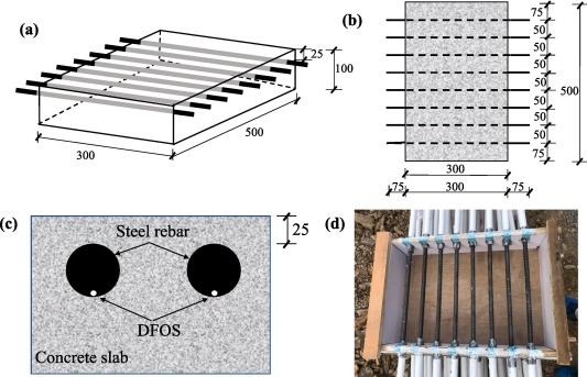
Figure 1. Application of the DFOS Testing Device
In an experiment by the Blagonravov Mechanical Engineering Research Institute of Russian Academy of Science on the stress-strain state of structures subjected to high-temperature liquid metal coolants, A batch of seal strain gauges manufactured according to an optimized process (nickel welded seal) was used, especially in high temperature areas, to study the stress-strain state of the heat exchanger under the action of high temperature liquid metal coolant. For example, when studying an intermediate heat exchanger (IHE) element, the degree of the strain gauge determines which interface regions of the different heat capacity elements where the maximum stress occurs, providing important data for insight into the mechanical behavior of the reactor equipment structure [8].
4 Analysis of development trends
4.1 Advantages
(1) High Measurement Accuracy
These sensors offer high sensitivity and precision, capable of providing sufficiently accurate measurements for most experimental environments.
(2) Good Reliability
Under suitable working environments and conditions, these sensors can operate stably and provide reliable measurement data. With proper design, manufacturing, and installation, they can maintain stable performance over extended periods, reducing the likelihood of data errors or inaccurate measurements due to sensor failures [9].
(3) Wide Range of Applications
These sensors are used in various fields. In mechanical manufacturing, they monitor the strain on metal components during processing, assembly, and use, ensuring product quality and safety. In civil engineering, they enable strain monitoring of metal structures such as bridges and buildings, helping prevent structural damage. In aerospace, they monitor strain on metal components like aircraft wings and engines to ensure flight safety. In electronics, they measure strain on metal parts within electronic components, ensuring proper operation of devices. In biomedicine, certain sensors measure strain on implanted metal devices within the human body, among other applications.
4.2 Disadvantages
(1) Susceptible to Environmental Interference
Each type of sensor is affected to varying degrees by environmental factors. For instance, the resistance of strain gauges in resistance sensors is temperature-dependent, meaning that measurements can be influenced by environmental temperature. Hall sensors are susceptible to interference from external magnetic fields, often requiring electromagnetic shielding. The capacitance value in capacitive sensors may vary due to changes in air temperature, humidity, and surrounding electromagnetic fields, and piezoelectric sensor performance can also be affected by temperature and humidity.
(2) Limited Adaptability to Complex Environments
In extreme environments, such as those with high temperature, high pressure, strong corrosion, or intense radiation, sensor performance may degrade or even lead to damage, especially for sensors that rely on microscopic electronic movements for measurement. While some sensors can be designed with special materials and configurations to improve adaptability to certain harsh environments, in general, sensors in extreme conditions are prone to damage and increased data inaccuracies.
(3) High Signal Processing Requirements
The signals output by these sensors often require processing to yield useful measurement results. For example, resistance strain sensors need signal conditioning via Wheatstone bridge circuits; fiber optic sensors require optical-to-electrical conversion and signal demodulation; Hall sensor outputs may need amplification, filtering, and linearization; capacitive sensors’ weak capacitance variation signals need amplification and conversion; and piezoelectric sensors require appropriate amplification and processing of the electrical signals. This increases the complexity of the entire stress measurement setup and raises the cost of maintenance and calibration.
4.3 Future development trends
(1) Enhancement of Sensor Performance
Sensors are expected to become more compact. With advancements in micro- and nano-fabrication technologies, these sensors can be integrated more closely onto or within metal surfaces, removing spatial limitations for applications with strict space requirements. This will allow precise strain monitoring even for small metal parts. Accuracy will also improve, with the development of new sensitive materials playing a key role. For example, resistance strain sensors may use materials with higher strain coefficients, and fiber optic sensors could utilize higher-quality fiber cores to enhance metal strain sensitivity. Additionally, lower power consumption is another critical trend. By using low-power chips, optimized circuit designs, and energy-efficient sensor components, the energy required for long-term strain monitoring can be significantly reduced, enabling more devices to operate on battery power alone [1].
(2) Automation and Intelligence in Data Processing
Data processing is expected to become more automated and intelligent. Sensors will gain enhanced real-time data processing capabilities, enabling preliminary processing such as noise filtering, weak signal amplification, and key feature extraction while collecting metal strain data. This will reduce data transmission volume and errors. Furthermore, integrating AI technology will be a central development direction. AI algorithms can learn normal and abnormal strain patterns in metals, allowing accurate differentiation between sensor malfunctions and structural issues when anomalies occur, and can even predict potential failure timelines to provide proactive maintenance guidance. Additionally, AI can adjust sensor measurement parameters, such as sensitivity and range, based on environmental conditions and strain characteristics, further enhancing measurement accuracy and reliability to ensure precise monitoring of metal strain in complex conditions.
5 Summary
This paper analyzes five types of sensors used for measuring metal strain: resistance sensors, fiber optic sensors, piezoelectric sensors, Hall sensors, and capacitive sensors. It details their working principles, including methods based on conductor deformation, changes in light signals, the piezoelectric effect, the Hall effect, and variations in capacitance values for strain or stress measurement. The study also reviews their practical applications in experimental settings, such as door-opening monitoring, strain measurement in steel beams, and stress testing of crane structures. Additionally, their advantages and disadvantages are discussed, with strengths like high measurement accuracy and drawbacks including susceptibility to environmental interference. Finally, the paper explores future development trends, projecting smaller sizes, higher accuracy, and lower power consumption for the sensors themselves, along with more automated and intelligent data processing capabilities, to achieve more precise monitoring of metal strain.
References
[1]. Javaid, M., et al. (2021). Sensors for daily life: A review. Sensors International, 2, 100121.
[2]. Soloman, S. (2009). Sensors handbook. McGraw-Hill, Inc.
[3]. Fleming, W. J. (2001). Overview of automotive sensors. IEEE Sensors Journal, 1(4), 296-308.
[4]. Nosseir, A. E. S., et al. (2024). Composite structures with embedded fiber optic sensors: A smart propellant tank for future spacecraft applications. Acta Astronautica, 223, 144-158.
[5]. Sirohi, J., & Chopra, I. (2000). Fundamental understanding of piezoelectric strain sensors. Journal of Intelligent Material Systems and Structures, 11(4), 246-257.
[6]. Gibiino, G. P., et al. (2023). Experimental evaluation of Hall-effect current sensors in BCD10 technology. Measurement, 220, 113289.
[7]. Anand, L. D. V., et al. (2021). Automatic strain sensing measurement on steel beam using strain gauge. Materials Today: Proceedings, 45, 2578-2580.
[8]. Maslov, S. V. (2023). Application of a full-scale strain gauge to study the stress-strain state of structures subjected to the action of a liquid-metal coolant at high temperatures. Procedia Structural Integrity, 50, 178-183.
[9]. Jin, T., Park, S. -H. K., & Fang, D. -W. (2022). Highly-stable flexible pressure sensor using piezoelectric polymer film on metal oxide TFT. RSC Advances, 12(33), 21014-21021.
Cite this article
Wei,Z. (2024). Stress sensors for metal workpiece fatigue testing. Advances in Engineering Innovation,14,30-34.
Data availability
The datasets used and/or analyzed during the current study will be available from the authors upon reasonable request.
Disclaimer/Publisher's Note
The statements, opinions and data contained in all publications are solely those of the individual author(s) and contributor(s) and not of EWA Publishing and/or the editor(s). EWA Publishing and/or the editor(s) disclaim responsibility for any injury to people or property resulting from any ideas, methods, instructions or products referred to in the content.
About volume
Journal:Advances in Engineering Innovation
© 2024 by the author(s). Licensee EWA Publishing, Oxford, UK. This article is an open access article distributed under the terms and
conditions of the Creative Commons Attribution (CC BY) license. Authors who
publish this series agree to the following terms:
1. Authors retain copyright and grant the series right of first publication with the work simultaneously licensed under a Creative Commons
Attribution License that allows others to share the work with an acknowledgment of the work's authorship and initial publication in this
series.
2. Authors are able to enter into separate, additional contractual arrangements for the non-exclusive distribution of the series's published
version of the work (e.g., post it to an institutional repository or publish it in a book), with an acknowledgment of its initial
publication in this series.
3. Authors are permitted and encouraged to post their work online (e.g., in institutional repositories or on their website) prior to and
during the submission process, as it can lead to productive exchanges, as well as earlier and greater citation of published work (See
Open access policy for details).
References
[1]. Javaid, M., et al. (2021). Sensors for daily life: A review. Sensors International, 2, 100121.
[2]. Soloman, S. (2009). Sensors handbook. McGraw-Hill, Inc.
[3]. Fleming, W. J. (2001). Overview of automotive sensors. IEEE Sensors Journal, 1(4), 296-308.
[4]. Nosseir, A. E. S., et al. (2024). Composite structures with embedded fiber optic sensors: A smart propellant tank for future spacecraft applications. Acta Astronautica, 223, 144-158.
[5]. Sirohi, J., & Chopra, I. (2000). Fundamental understanding of piezoelectric strain sensors. Journal of Intelligent Material Systems and Structures, 11(4), 246-257.
[6]. Gibiino, G. P., et al. (2023). Experimental evaluation of Hall-effect current sensors in BCD10 technology. Measurement, 220, 113289.
[7]. Anand, L. D. V., et al. (2021). Automatic strain sensing measurement on steel beam using strain gauge. Materials Today: Proceedings, 45, 2578-2580.
[8]. Maslov, S. V. (2023). Application of a full-scale strain gauge to study the stress-strain state of structures subjected to the action of a liquid-metal coolant at high temperatures. Procedia Structural Integrity, 50, 178-183.
[9]. Jin, T., Park, S. -H. K., & Fang, D. -W. (2022). Highly-stable flexible pressure sensor using piezoelectric polymer film on metal oxide TFT. RSC Advances, 12(33), 21014-21021.