


1. Introduction
In recent years, several scholars have conducted research on machine vision sorting technology. Chen Xiaohong designed a visual recognition and positioning method using image sensing technology to achieve intelligent material sorting [1]. Deng Huajun et al. utilized RobotStudio software to design Smart components such as dynamic material conveying chains and dynamic quick-change tools, simulating the robot palletizing process [2]. Feng Lingyun et al. took the production of chocolate biscuits in a food company as an example, proposing a method combining conveyor tracking and visual recognition technology to achieve dynamic tracking and sorting of randomly placed materials into boxes [3]. Hao Ruilin et al. addressed the difficulty of packing disorderedly placed boxed biscuits by using VisionMaster software to identify the offset position and angle of the boxes [4]. Peng Huihui et al. studied an industrial robot sorting system based on mobile vision [5].Wen Shuangquan et al. utilized the ABB IRB120 industrial robot as a platform and designed a robotic vision sorting simulation workstation based on the RobotStudio simulation environment [6].Due to the current lack of technological maturity in China and the challenges posed by diverse application fields, the return on investment for machine vision sorting technology is relatively low, which affects companies' willingness to invest and, consequently, the promotion and application of this technology.
This paper employs RobotStudio software to design a visual material sorting simulation workstation based on the IRB4600 robot. By leveraging the functionalities of various Smart components, the workstation successfully proposes an efficient and accurate automated sorting solution for express delivery or bulk packaged food products.
2. Model construction and work tasks
2.1. Work environment construction
This article uses three IRB4600 robots and selects the conveyor chain guide as the conveyor belt model (hereinafter referred to as conveyor belt 1, conveyor belt 2, and conveyor belt 3). Layout all the equipment in the production line, establish a complete work platform, and encircle the work area with multiple fences, as shown in Figure 1.
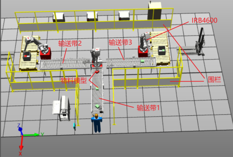
Figure 1. 3D environment effect diagram
2.2. Material model construction
In this study, we developed an automated material sorting system using the ABB RobotStudio simulation platform. For effective robotic manipulation, the sorting targets were modeled as cuboidal geometries with dimensions of 200mm × 150mm × 100mm (L×W×H), as illustrated in Figure 2. Two distinct material types were simulated using identical-sized cuboids differentiated by color coding - green and red blocks. This design approach serves dual purposes: the uniform geometry optimizes end-effector grasping reliability, while chromatic differentiation enables visual recognition system training for material classification.
.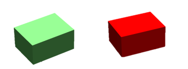
Figure 2. Material model
Material presentation mechanism: To simulate realistic industrial conditions, the feeding system was programmed with a conveyor speed of 300mm/s. The material appearance followed a stochastic pattern with randomized emergence timing and angular offsets of 2-3 degrees from the central axis. This controlled variability was intentionally incorporated to test the system's robustness in handling positional uncertainties and to validate the effectiveness of our visual servo compensation algorithms under non-ideal feeding conditions.
2.3. Work tasks
The workstation is designed to enable the IRB4600 robotic system to dynamically pick up materials from Conveyor 1 and systematically arrange them onto either Conveyor 2 or 3 based on color differentiation. Subsequently, two additional IRB4600 robots positioned near Conveyors 2 and 3 perform the material sorting operations.
The system operates under the following specifications: Materials are loaded at the starting point of Conveyor 1 with randomized initial positions and orientations, then transported along the conveyor until reaching a predetermined stopping position. Conveyor 1 operates in an intermittent mode, while Conveyors 2 and 3 maintain continuous operation. The robotic system implements real-time dynamic tracking of materials moving on Conveyors 2 and 3, initiating the sorting process when targets enter the predefined grasping zone. This operational cycle repeats continuously, with the final packaged products being discharged at the terminal ends of Conveyors 2 and 3.
Table 1. I/O signals and connections for loading and unloading tool assembly
Source object | Source signal | Target object | Target signal or attribute |
LineSensor_2 | SensorOut | Attacher | Execute |
LogicGate | 0utput | Detacher | Execute |
Gripper _1 | Di_Gripper2 | LineSensor_2 | Active |
Gripper _1 | Di_Gripper2 | LogicGate_2[NOT] | InputA |
3. Workstation system configuration
3.1. Configuring I/O system
The configuration of the I/O System is a critical component in robot programming and simulation, as it enables users to define and emulate the input/output signal interactions between the robot and external devices (see Table 1).
In the Signal configuration, new signals including Green, Red, Di_BoxInPos, and Do_Gripper were created, with their respective signal types assigned. The specific types are detailed in Table 2.
Table 2. Types of new Signal
Name | Type of Sige | Name | Type of Sige |
Di_BoxInPos | Digital Input | Green | Digital Intput |
Di_BoxInPos_2 | Digital Input | Do_Gripper | Digital Output |
Di_BoxInPos_3 | Digital Intput | Do_Gripper_2 | Digital Output |
Red | Digital Intput | Do_Gripper_3 | Digital Output |
St | Digital Output |
3.2. PLC variable settings and workstation logic
Establish a connection with S7-PLCSIM Advanced and add the RSConnectDIOToSnap7 plugin to enable communication between RobotStudio and PLCSim Advanced. Then, create the PLC variables required for communication and associate all subcomponents in the design, as illustrated in Figure 3.
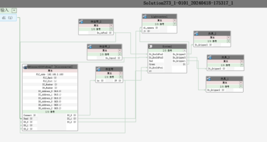
Figure 3. Overall logical relationship of workstation
4. Robotic sorting system program design
4.1. Setting teaching points and paths
(1) Set the required teaching points: Manually move the robot to set teaching point 1 at the grabbing position, teaching point 2 above the grabbing position, teaching point 3 above the placement position, and teaching point 4 at the placement position.
(2) Set the path: Adjust the robot's posture as needed, move the tool to the target point, and click the teaching command to generate the corresponding point command. Use the same method to teach other target points. Set the sequence of teaching points to form a path (the Rapid program and the teaching point path in the workstation must be synchronized).
(3) Repeat the above steps to complete the setting of all teaching points and paths, as shown in Figures 4 and 5.
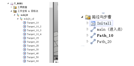
Figure 4. Target Points and Required Path for Robotic Arm 1
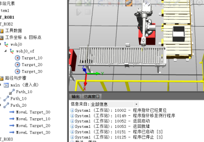
Figure 5. Target Points and Required Path for Robotic Arms 2 and 3
(4) Configure parameters for the target points, drag all the configured target points into the path Path_10 in sequence, and synchronize them to the workstation.
(5) Add two signals in the controller configuration: one arrival signal for conveyor belt waiting, and one suction cup signal. Restart the controller after adding these signals.
4.2. Loading and unloading path planning and TCP tracking
(1) Before planning the loading and unloading paths for the robot, it is necessary to conduct a detailed analysis of the robot's workspace, including the robot's reachable range, the layout of the workbench, and any potential obstacles. This ensures that the planned paths are within the robot's physical capabilities and effectively avoid obstacles. Optimizing the planned paths can improve efficiency and accuracy. This includes reducing the total length of the path, smoothing the curvature of the path, and minimizing the number of accelerations and decelerations. By optimizing the path, the robot's motion performance in real-world scenarios can be enhanced, reducing unnecessary energy consumption and wear.
(2) The TCP (Tool Center Point) trajectory tracking function generates real-time trajectory lines during the robot's movement, allowing users to visually observe the motion path of the tool center point. The TCP trajectory tracking function visualizes the robot's motion trajectory in three-dimensional space. By observing and analyzing these trajectories, engineers and operators can understand the robot's motion state during task execution, including speed, acceleration, and displacement. This enables quick identification of potential interference risks during the robot's movement, which is crucial for ensuring operational safety. Users can utilize this function to adjust and optimize the layout of surrounding equipment to avoid conflicts with the robot's path. As shown in Figure 6.
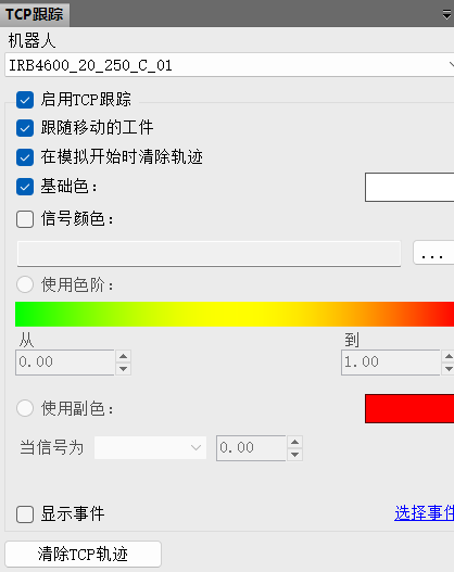
Figure 6. TCP Setup
In practical operations, the TCP trajectory tracking function can also be used to monitor the robot's operating status in real time.
The steps for each grasping and releasing action of Robotic Arm 1's tool on the material are as follows:
Initial (home) position of the robotic arm → directly above the material position → approaching the material → suction cup activation → waiting for 0.5 seconds → moving the robotic arm to the corresponding conveyor belt → releasing the material → returning the robotic arm to the home position. Repeat the above steps.
The TCP path of Robotic Arm 1 is shown in Figure 7.
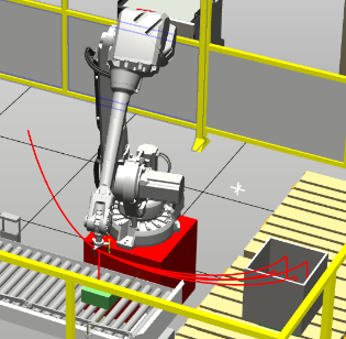
Figure 7. TCP Path Tracking of Robotic Arm 1
The paths of Robotic Arm 2 and Robotic Arm 3 are essentially the same. The steps for the grasping action are as follows:
Move the robotic arm directly above the material → approach the material → activate the suction cup → wait for 0.5 seconds → move the robotic arm to the corresponding position → release the material → return the robotic arm directly above the material. Repeat the above steps for each grasping action. The same applies to Robotic Arm 3. The working paths of Robotic Arm 2 and Robotic Arm 3 are shown in Figure 8.
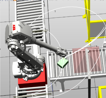
Figure 8. TCP Path Tracking of Robotic Arms 2 and 3
Allocate the storage positions of the created materials in sequential order, as shown in Figure 9.
Figure 9. Placement Sequence
4.3. Robotstudio and PLC programming
(1) This design requires one main program and two subroutines. One is for sorting, and the other two are for palletizing.
(2) Before the grasping program, a wait signal needs to be set, which is the signal to wait for the object to stop. This signal is transmitted to the controller according to the previously configured connection. Once the controller receives this signal, the robotic arm moves along the set path to the grasping point. Upon reaching the grasping point, the grasping signal is set. Then, the robotic arm moves to the placement point according to the set path. A reset instruction is placed after the path to the placement point to achieve the release action.
Partial trajectory code for Robotic Arm 1 is as follows:
PROC main()
WHILE TRUE DO
WaitDI Di_BoxInPos1, 1;
WaitTime 1; // Wait for 1 second
IF strpart(name, 1, 1) = "A" THEN // If the material is A
moveJ offs(Target_10, 0, 0, 200), v5000, fine, Tooldata_1\WObj:=wobj0; // Move above the material
MoveL offs(Target_10, 0, 0, 0), v500, fine, Tooldata_1\WObj:=wobj0; // Approach the material
WaitTime 0.5; // Wait for 0.5 seconds
SetDO Do_Gripper1, 1; // Activate the suction cup
WaitTime 0.5;
MoveL offs(Target_10, 0, 0, 200), v5000, fine, Tooldata_1\WObj:=wobj0;
// Move above the next conveyor
moveJ offs(Target_20, 0, 0, 200), v5000, fine, Tooldata_1\WObj:=wobj0;
// Move the material to the conveyor
WaitTime 0.5;
MoveL offs(Target_20, 0, 0, 0), v500, fine, Tooldata_1\WObj:=wobj0; // Place the material
WaitTime 0.5;
SetDO Do_Gripper1, 0; // Deactivate the suction cup
WaitTime 0.5;
MoveL offs(Target_20, 0, 0, 200), v5000, fine, Tooldata_1\WObj:=wobj0; // Return to the origin
(3) Palletizing program writing: Since only four materials can be placed in the first layer of a box, the palletizing program should include four case programs.
The partial code for the handling process is as follows:
CASE 1: MoveJ offs(Target_20,0,0,300+z),v5000,fine,Tooldata_2\WObj:=wobj0; MoveJ offs(Target_20,0,0,z),v1000,fine,Tooldata_2\WObj:=wobj0; WaitTime 1; Reset Do_Gripper2; WaitTime 1; MoveJ offs(Target_20,0,0,300+z),v3000,fine,Tooldata_2\WObj:=wobj0; |
5. Conclusion
This study designed a vision-based material sorting simulation workstation using RobotStudio, leading to the following conclusions:
1. Improved Accuracy and Efficiency: By utilizing RobotStudio's simulation platform, a sorting workstation integrating a vision system and robot control was designed, successfully enhancing the accuracy and efficiency of material sorting.
2. Enhanced Coordination and Fluidity: Through reasonable equipment layout and the application of intelligent components, the coordination of each process was ensured, improving the fluidity of material transportation and sorting.
3. Optimized Path Planning and TCP Tracking: The application of path planning and TCP tracking for robotic arms significantly reduced energy consumption and wear during robot motion, improving task execution precision and speed.
4. Stability and Reliability: The simulation results show that the designed workstation exhibits excellent stability and reliability during continuous operation tests, maintaining efficient performance over extended periods.
This study not only realized an efficient and accurate automated sorting system but also provided a feasible design solution and theoretical foundation for the further promotion of robot vision technology in industrial applications.
References
[1]. Chen, X. H. (2024). Research on Key Technologies of Intelligent Material Sorting System Based on Industrial Robot Vision [D]. Jinan University. https://doi.org/10.27167/d.cnki.gjinu.2022.000710
[2]. Deng, H. J., Duan, Y. H., & Lu, P. W. (2023). Virtual Simulation Platform for Robot Handling and Palletizing Based on RobotStudio. Automation and Information Engineering, 44(1), 27-32.
[3]. Feng, L. Y., Zeng, X. P., Li, Q., & Wang, C. F. (2023). Simulation of Robot Sorting and Packaging Workstation Based on Conveyor Belt and Visual Tracking. Packaging Engineering, 44(13), 227-235.
[4]. Hao, R. L., Zhou, L. J., Cai, G. Q., Liu, H., & Sun, Y. J. (2022). Simulation of Biscuit Packaging Production Line Based on Machine Vision and RobotStudio. Packaging and Food Machinery, 40(1), 64-69.
[5]. Peng, H. H., Liu, F. F., Dai, Y. Y., Chen, Z. Y., & Chen, W. T. (2020). Application Research of Industrial Robot Sorting System Based on Mobile Vision. Modern Electronics Technique, 43(20), 26-30.
[6]. Wen, S. Q., Song, Z. D., & Zhao, W. (2023). Design of Robot Vision Sorting Simulation Workstation. Changjiang Information & Communications, 36(4), 32-35+38.
Cite this article
Long,L.;Li,Y.;Yang,X.;Tang,Q.;Feng,Y. (2025). Design of visual material sorting simulation workstation based on RobotStudio. Advances in Engineering Innovation,16(3),24-30.
Data availability
The datasets used and/or analyzed during the current study will be available from the authors upon reasonable request.
Disclaimer/Publisher's Note
The statements, opinions and data contained in all publications are solely those of the individual author(s) and contributor(s) and not of EWA Publishing and/or the editor(s). EWA Publishing and/or the editor(s) disclaim responsibility for any injury to people or property resulting from any ideas, methods, instructions or products referred to in the content.
About volume
Journal:Advances in Engineering Innovation
© 2024 by the author(s). Licensee EWA Publishing, Oxford, UK. This article is an open access article distributed under the terms and
conditions of the Creative Commons Attribution (CC BY) license. Authors who
publish this series agree to the following terms:
1. Authors retain copyright and grant the series right of first publication with the work simultaneously licensed under a Creative Commons
Attribution License that allows others to share the work with an acknowledgment of the work's authorship and initial publication in this
series.
2. Authors are able to enter into separate, additional contractual arrangements for the non-exclusive distribution of the series's published
version of the work (e.g., post it to an institutional repository or publish it in a book), with an acknowledgment of its initial
publication in this series.
3. Authors are permitted and encouraged to post their work online (e.g., in institutional repositories or on their website) prior to and
during the submission process, as it can lead to productive exchanges, as well as earlier and greater citation of published work (See
Open access policy for details).
References
[1]. Chen, X. H. (2024). Research on Key Technologies of Intelligent Material Sorting System Based on Industrial Robot Vision [D]. Jinan University. https://doi.org/10.27167/d.cnki.gjinu.2022.000710
[2]. Deng, H. J., Duan, Y. H., & Lu, P. W. (2023). Virtual Simulation Platform for Robot Handling and Palletizing Based on RobotStudio. Automation and Information Engineering, 44(1), 27-32.
[3]. Feng, L. Y., Zeng, X. P., Li, Q., & Wang, C. F. (2023). Simulation of Robot Sorting and Packaging Workstation Based on Conveyor Belt and Visual Tracking. Packaging Engineering, 44(13), 227-235.
[4]. Hao, R. L., Zhou, L. J., Cai, G. Q., Liu, H., & Sun, Y. J. (2022). Simulation of Biscuit Packaging Production Line Based on Machine Vision and RobotStudio. Packaging and Food Machinery, 40(1), 64-69.
[5]. Peng, H. H., Liu, F. F., Dai, Y. Y., Chen, Z. Y., & Chen, W. T. (2020). Application Research of Industrial Robot Sorting System Based on Mobile Vision. Modern Electronics Technique, 43(20), 26-30.
[6]. Wen, S. Q., Song, Z. D., & Zhao, W. (2023). Design of Robot Vision Sorting Simulation Workstation. Changjiang Information & Communications, 36(4), 32-35+38.