


1. Introduction
Microwave-absorbing composites are structural functional materials that simultaneously provide electromagnetic absorption and load-bearing protection. Structural components made from such materials can replace or partially substitute corresponding metal structures on a target, thereby significantly reducing the likelihood of radar detection while also lowering the weight of weapon systems. These composites have received significant attention both domestically and internationally, and have rapidly progressed into engineering applications. They are composed of absorbers, resin matrices, and reinforcing fiber fabrics. Currently, microwave-absorbing composites fabricated with absorbers can achieve good absorption performance in the 1–18 GHz range at a certain thickness. However, to achieve broadband absorption under thickness constraints, magnetic absorbers are often required. Magnetic absorbers have high density and require high filler loading, which increases the weight of composite structural components and alters their physical and mechanical properties [1]. Introducing Frequency Selective Surfaces (FSS) into composites can help mitigate the issues of increased weight and limited absorption bandwidth. As a relatively new research direction in the field of absorbing materials, FSS has attracted considerable academic attention in recent years [2-6]. In such media, electric and magnetic fields are coupled, and both the permittivity and permeability can be negative simultaneously. This so-called double-negative property gives FSS many unique electromagnetic characteristics not found in natural materials [7,8]. As research on these materials has progressed, it has been recognized that the key advantage of FSS is the ability to tailor the required refractive index, permittivity, and permeability through structural design, providing excellent potential for applications in absorbing materials.
Current FSS fabrication techniques mainly include printed circuit board processes, mechanical assembly, microelectronic etching, and screen printing, among others [9-11]. In this study, an FSS was fabricated using a conductive fiber knitting process on glass fiber fabric and then integrated into composites. This process enables precise control of material parameters such as the conductivity of the fibers and structural parameters like unit cell dimensions, and helps address technical challenges in implementing existing FSS manufacturing methods on three-dimensional curved or multilayer structures.
Although in theory it is possible to achieve the required electromagnetic parameters for impedance matching through FSS design—thereby enabling near-zero reflection for normally incident waves—in practical applications, absorbing materials must also feature broadband, wide-angle, polarization-insensitive performance with low profile and lightweight characteristics. For normal incidence, the free-space impedance of the medium is the same for different polarizations, so it is unnecessary to distinguish polarization when evaluating normal-incidence absorption performance. However, under oblique incidence, the free-space impedance of the material changes in opposite trends for TE and TM waves as the incident angle increases [12,13]. Therefore, when investigating the absorption characteristics of materials under oblique incidence, both TE and TM wave incidences must be considered. However, single-layer two-dimensional FSS structures suffer from issues such as non-uniformity, anisotropy, polarization sensitivity, and narrow operating bandwidth. In contrast, laminated composite materials allow for multilayer design, greatly increasing the design flexibility of absorbing structures.
Given the resonant absorption characteristics of FSS, researchers have first considered combining FSS with different traditional absorbing materials to broaden the absorption bandwidth of stealth composites. In particular, given the demands for weight reduction and corrosion resistance, the use of dielectric-loss-type absorbing composites has been increasing. However, their low-frequency absorption performance is constrained by thickness. By controlling the material parameters and unit cell dimensions of the FSS to tune its electromagnetic response band, and managing the propagation and reflection characteristics of electromagnetic waves within the absorbing array, it is possible to achieve low-frequency absorption functionality, thereby overcoming thickness limitations and expanding the application range [14,15].
2. Experimental
2.1. Materials
Glass fiber fabric (EW200, China National Building Material Technology Co., Ltd.); Silver-plated yarn (150D, Dongguan Sovit Special Webbing Co., Ltd.); Carbon black (TS530, Guangzhou Jingyi New Materials Co., Ltd.); Medium-temperature curing epoxy resin (ME301, Zhengzhou University)
2.2. Sample preparation
Preparation of conductive fiber fabric: A knitting process was used to form a periodic array structure by integrating silver-plated yarn onto glass fiber fabric with a fully automated computerized flat knitting machine.
Preparation of microwave-absorbing prepreg: Carbon black (4 wt%) was mixed with the medium-temperature curing epoxy resin (ME301), then processed by three-roll milling. A resin film with an areal density of approximately 50 g/m² was produced via film-coating, and combined on both sides with glass fiber fabric to obtain the microwave-absorbing prepreg. Similarly, a wave-transmitting prepreg was prepared by laminating unfilled epoxy resin with EW200 glass fiber fabric using the same process.
Preparation of composite specimens: Microwave-absorbing laminate specimens were fabricated via compression molding and cut into approximately 180 mm × 180 mm squares.
2.3. Characterization and performance testing
Equipment: Electromagnetic parameter testing device, vector network analyzer, arch method reflectivity test fixture, fully automated computerized flat knitting machine, digital multimeter.
Reflectivity performance testing: The reflectivity of the microwave-absorbing laminate specimens was measured using the arch method specified in GJB 2038-2011A, over the frequency range of 4–18 GHz.
3. Results and discussion
3.1. Electromagnetic parameter characteristics
Using computer simulations and the parameter inversion method described in [16], the equivalent electromagnetic parameters of FSS materials with different conductivities were obtained. The CST software was used to investigate a single-direction split-ring structure, analyzing variations in equivalent parameters as the conductivity ranged from 10 to 10⁵ S/m. As shown in Figure 1, the left, center, and right components represent the split-ring, substrate material, and reflector material, respectively. The substrate thickness was 3 mm; the outer and inner radii of the ring were 8 mm and 6 mm, with a gap of 1 mm. The unit cell had a side length of 20 mm, and the ring thickness was 0.1 mm. The substrate used the software’s built-in FR-4 material (dielectric constant = 4.3), and the reflector was modeled as a Perfect Electric Conductor (PEC). Simulated reflectivity curves are shown in Figure 2, and S-parameter curves are presented in Figure 3, 4, and 5.
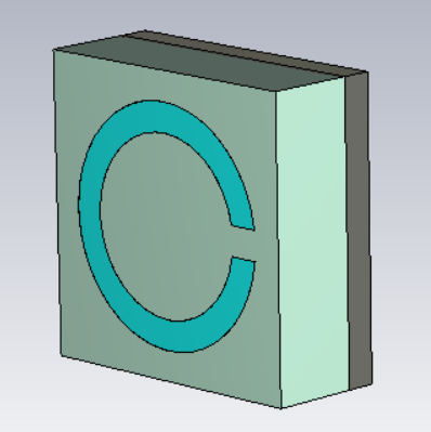
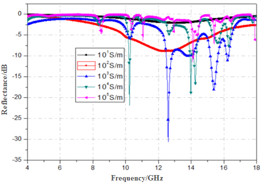
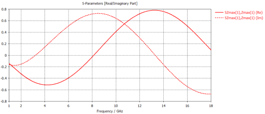
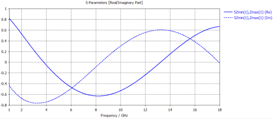
Figure 3. S-parameters at conductivity of 10 S/m
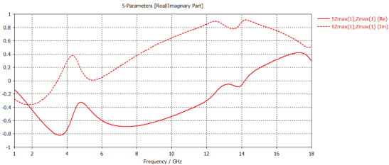
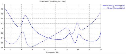
Figure 4. S-parameters at conductivity of 10³ S/m
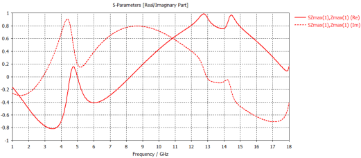
Figure 5. S-parameters at conductivity of 10⁵ S/m
The simulation results show that as conductivity increases, both absorption bandwidth and depth improve. When conductivity exceeds 10² S/m, multiple absorption peaks begin to appear, exhibiting narrowband absorption characteristics. Overall, conductivities in the range of 10²–10³ S/m achieve a good balance between bandwidth and absorption depth.
Based on the simulated S11 and S21 data, equivalent electromagnetic parameters were obtained via inversion to generate three-dimensional plots of permittivity and permeability versus frequency and logarithmic conductivity, as shown in Figure 6.
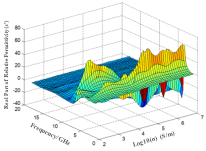
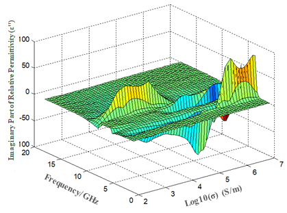
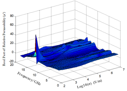
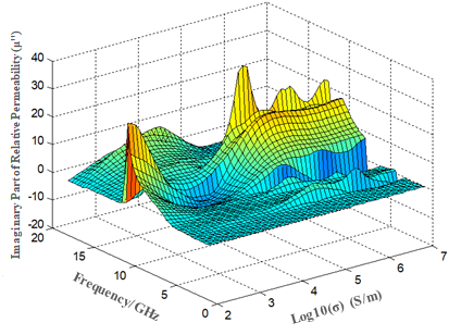
Figure 6. 3D plots of equivalent electromagnetic parameters vs. frequency and conductivity
From these 3D plots, it is evident that at higher frequencies, variations in conductivity lead to minimal changes in permittivity (real and imaginary parts), while permeability varies more significantly. This indicates that the main resonant mode of the FSS structure remains unchanged in this frequency range. In the 4–5 GHz band, when conductivity exceeds 10⁴ S/m, both permittivity and permeability exhibit significant fluctuations, reflecting complex resonant effects and explaining, from an electromagnetic perspective, the origin of absorption peaks in this band.
3.2. Normal-incidence reflectivity of laminated composites with single-layer conductive fiber FSS
According to the unit cell dimensions described in Section 3.1, silver-plated yarn FSS materials were prepared following the methods in Section 2.2. Due to differences in knitting precision and density, measured unit cell conductivities ranged from 100 to 500 S/m, with an average of approximately 200 S/m. These FSS fabrics were laminated with resin films and compression molded to form composite laminates. Reflectivity was measured using the arch method to evaluate microwave absorption performance. The fabricated silver-plated yarn FSS fabric and composite laminate specimens are shown in Figure 7, with their reflectivity results presented in Figure 8.
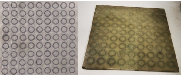
Figure 7. Photographs of conductive fiber fabrics and laminated composites
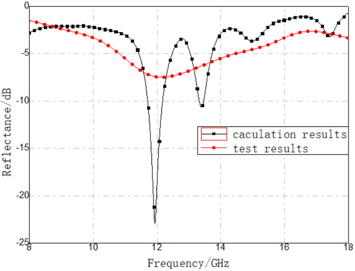
Based on the model in Section 3.1, a conductivity of 200 S/m was used in simulations to calculate normal-incidence reflectivity, which was then compared with experimental results in Figure 8. The comparison shows good agreement in peak frequencies and similar average reflectivity values. However, the measured reflectivity curve is flatter and exhibits fewer absorption peaks. This difference arises because the simulation model assumes perfectly uniform unit cell dimensions, leading to strong resonances at specific frequencies, whereas real samples have dimensional variations, resulting in broader size distributions. Additionally, while the simulation uses the measured fiber conductivity as the unit cell value, the actual structure cannot be perfectly densely packed with conductive fibers, leaving gaps that result in laminate performance resembling that of lower-conductivity FSS materials—namely, shallower absorption peaks and broader bandwidth.
3.3. Oblique-incidence reflectivity of laminated composites with single-layer conductive fiber FSS
When exposed to oblique microwave incidence, an absorbing panel cannot simultaneously match the impedance of free space for both TE and TM polarizations. In practical applications, it is necessary for the absorber to handle incident electromagnetic waves of any polarization and any angle of incidence while maintaining low reflectivity for both TE and TM modes to ensure effective absorption performance.
In engineering applications, when reflectivity is expressed in decibels, the reflectivity of an N-layer absorbing panel under oblique incidence can be represented as:
At resonance, if the input impedance at the interface between the absorbing panel and free space is designed to be close to 377 Ω, a good compromise in reflectivity can be achieved for both TE and TM polarizations, leading to optimal absorption performance under oblique incidence.
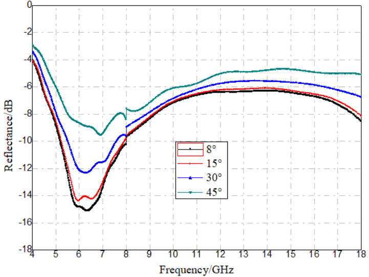
This formula indicates the theoretical optimum for single-layer panels to achieve polarization-compatible absorption under oblique incidence. Analysis of the input impedance at the free-space/N-layer interface shows that multilayer panels have impedance characteristics similar to single layers; the only parameter affected by the angle of incidence is the transmission angle within each layer. By carefully designing and controlling the electromagnetic parameters of each layer, this angle dependence can be effectively minimized, making the input impedance nearly independent of the angle of incidence. Therefore, when the interface impedance approaches 377 Ω, a good compromise between TE and TM reflectivity is achieved, ensuring excellent absorption performance under oblique incidence. Based on this principle, we continued to use the single-layer FSS design described in Section 2.2, integrating it into resin-based glass-fiber composites whose surface impedance is close to 377 Ω. Using the arch method, we measured the reflectivity of these laminates at incidence angles of 15°, 30°, and 45°, for both vertically and horizontally polarized waves. The results are shown in Figure 9.
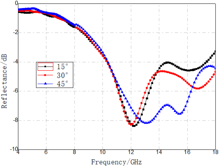
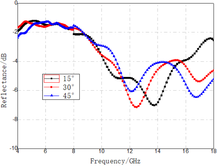
Figure 9. Oblique-incidence reflectivity test curves for single-layer silver-plated fiber FSS material
As shown in Figure 9, the oblique-incidence reflectivity for both vertical and horizontal polarizations did not increase; in fact, there was some reduction in reflectivity in the 8–18 GHz band. This indicates that the material's reflectivity is relatively insensitive to changes in polarization and angle of incidence.
3.4. Broadband absorption characteristics of laminated composites with single-layer conductive fiber FSS
Under certain thickness constraints (e.g., 4 mm), dielectric-loss-type absorbing composites typically perform well in the high-frequency portion of the 2–18 GHz range but show poor absorption in the lower frequencies. By combining FSS with dielectric-loss-type absorbing composites, it is possible to leverage the light weight of both systems while also taking advantage of the FSS’s frequency-selective resonant absorption characteristics and the strong high-frequency absorption of the dielectric-loss composite. This combination can produce broadband absorption effects.
In the experiment, dielectric-loss-type laminated absorbing composites were first prepared using carbon-black-loaded prepreg. Their measured electromagnetic parameters are shown in Table 1. Based on the interlayer structure shown in Figure 10(a), the simulated vertical-incidence reflectivity curves before and after adding the H-shaped FSS structure (shown in Figure 10(b)) were calculated. The results are presented in Figure 10(c). These curves demonstrate that the FSS structure improves the absorption depth and broadens the absorption band of the composite.
|
Electromagnetic parameters Frequency (GHz) |
ε' |
ε'' |
μ' |
μ'' |
|
2 |
7.35 |
3.05 |
1.06 |
0.3 |
|
4 |
6.4 |
2.23 |
1.09 |
0.17 |
|
6 |
6.07 |
1.84 |
1.08 |
0.14 |
|
8 |
5.81 |
1.80 |
1.05 |
0.1 |
|
10 |
5.49 |
1.71 |
1.06 |
0.09 |
|
12 |
5.42 |
1.59 |
1.03 |
0.11 |
|
14 |
5.21 |
1.66 |
1.01 |
0.06 |
|
16 |
5.02 |
1.47 |
1.02 |
0.04 |
|
18 |
5.01 |
1.45 |
1.01 |
0.02 |
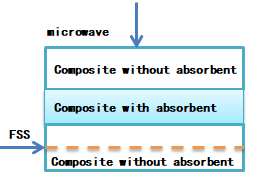
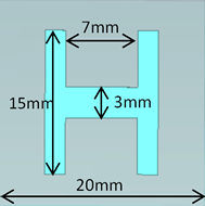
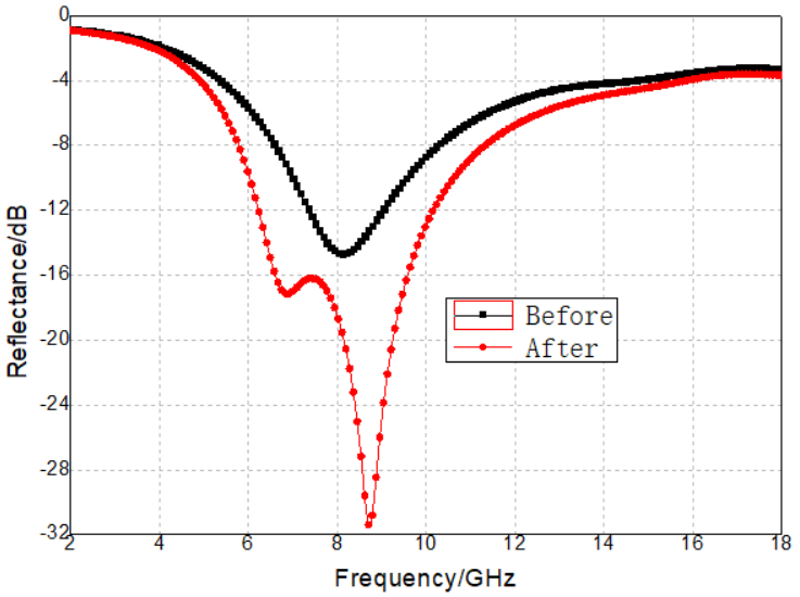
Figure 10. Layer structure, FSS unit dimensions, and simulated reflectivity curves before and after adding dielectric-loss composite
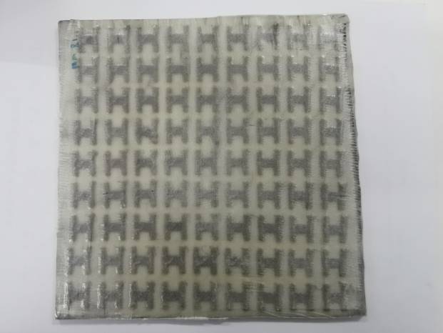
Building on this, a new absorbing composite was fabricated by integrating conductive fiber FSS fabric with dielectric-loss-type absorbing prepreg, incorporating an H-shaped conductive fiber FSS design. Reflectivity testing confirmed that the conductive fiber FSS significantly enhances the low-frequency absorption performance of the dielectric-loss composite. The reflectivity variations under both polarization states and at different incidence angles were also investigated. A photograph of the actual composite laminate is shown in Figure 11.
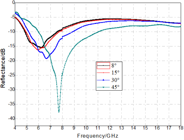
(b) Horizontal polarization oblique-incidence reflectivity curves
Figure 12. Measured reflectivity curves of conductive fiber FSS–dielectric-loss composite laminates at different incidence angles
Figures 12(a) and 12(b) show the measured vertical and horizontal polarization oblique-incidence reflectivity curves of the laminate after incorporating the conductive fiber FSS into the dielectric-loss composite. The laminate structure was the same as that in Figure 10(a), with the layers along the incident wave direction arranged as follows: wave-transmitting composite (without carbon black), absorbing composite (with carbon black), wave-transmitting composite, conductive fiber FSS, and wave-transmitting composite. The final laminate thickness was 3.7 mm. The absorption bandwidth with reflectivity below –4 dB was extended from the original 6–14 GHz to 5–18 GHz.
4. Conclusion
The electrical conductivity of Frequency-Selective Surface (FSS) materials has a significant effect on their microwave absorption performance. At higher conductivities (above 10⁷ S/m), the characteristic absorption peaks become stronger but the absorption bandwidth narrows. As the conductivity decreases below 10⁷ S/m, the absorption peaks become shallower and the bandwidth broadens. Single-layer open-ring-type FSS structures fabricated using silver-plated fibers and integrated with wave-transmitting composites demonstrate effective absorbing performance. For composites with a thickness of 3 mm, an average reflectivity of approximately –4 dB can be achieved in the Ku band. Furthermore, under oblique incidence for both vertical and horizontal polarizations, the reflectivity does not increase significantly, indicating reduced sensitivity to incident angle and polarization. By combining silver-plated fiber FSS materials with dielectric-loss-type absorbing composites, the absorption bandwidth of the dielectric-loss composites can be effectively broadened.
References
[1]. Zhou, Z., Wang, Y., Zhao, W., Wang, Z., & Zhao, Y. (2024). Study on thermal expansion coefficient and absorbing properties of fiber reinforced resin-based absorbing composites.Composites Part C: Open Access,14, 100449.
[2]. Lu, H., & Guo, Y. (2021). Study on equivalent circuit model of metamaterial perfect absorber.Electronic Components & Materials,40(6), 570–573, 577.
[3]. Li, K., Li, Z., Chen, H., Luo, W., & Weng, X. (2020). Study on broadband tunable radar absorbing materials based on graphene. Electronic Components & Materials, 39(6), 28–33.
[4]. Liu, X., Fan, K., Shadrivov, I. V., & Padilla, W. J. (2017). Experimental realization of a terahertz all-dielectric metasurface absorber.Optics Express, 25(1), 191–201.
[5]. Cao, M., Zhu, J., Yuan, J., Peng, Z., & Xiao, G. (2002). Simulation of multiple composite coatings based on conducting plate and investigation of microwave reflectivity.Microwave and Optical Technology Letters, 34(6), 442–445.
[6]. Dayal, G., & Ramakrishna, S. A. (2013). Design of multi-band metamaterial perfect absorbers with stacked metal–dielectric disks.Journal of Optics,15(5), 055106.
[7]. Guo, Y., Hou, X., Lv, X., Bi, K., Lei, M., & Zhou, J. (2017). Tunable artificial microwave blackbodies based on metasurfaces.Optics Express,25(21), 25879–25885.
[8]. Liu, J., Sano, Y., & Nakayama, A. (2009). A simple mathematical model for determining the equivalent permeability of fractured porous media.International Communications in Heat and Mass Transfer,36(3), 220–224.
[9]. Schurig, D., Mock, J. J., Justice, B. J., Cummer, S. A., Pendry, J. B., Starr, A. F., & Smith, D. R. (2006). Metamaterial electromagnetic cloak at microwave frequencies.Science,314(5801), 977–980.
[10]. Laila, D., Sujith, R., Shameena, V. A., Nijas, C. M., Sarin, V. P., & Mohanan, P. (2013). Complementary split ring resonator‐based microstrip antenna for compact wireless applications.Microwave and Optical Technology Letters,55(4), 814–816.
[11]. Zhou, Z., Zhao, Y., Wang, Z., & Cheng, H. (2023). The design and fabrication of a broadband meta-material absorber based on a double-layer ring structure.Journal of Magnetism and Magnetic Materials,586, 171203.
[12]. Gil, I., Bonache, J., Garcia-Garcia, J., & Martin, F. (2006). Tunable metamaterial transmission lines based on varactor-loaded split-ring resonators.IEEE Transactions on Microwave Theory and Techniques,54(6), 2665–2674.
[13]. Aydin, K., & Ozbay, E. (2007). Capacitor-loaded split ring resonators as tunable metamaterial components.Journal of Applied Physics, 101(2), 024911.
[14]. Zhao, H., Gong, Y., Xing, M., Ou, Q., & Lin, H. (2015). Design and application of multi-layer impedance gradient in structural absorbing materials.Aerospace Materials & Technology,45(4), 19–22.
[15]. Zhou, Z., Liu, Y., Chen, X., Wang, Z., & Zhao, Y. (2024). Study on properties of glass-fiber-fabric-reinforced microwave-absorbing composites.Materials, 17(7), 1453.
[16]. Hasar, U. C., Barroso, J. J., Sabah, C., Ozbek, I. Y., Kaya, Y., Dal, D., & Aydin, T. (2012). Retrieval of effective electromagnetic parameters of isotropic metamaterials using reference-plane invariant expressions.Progress In Electromagnetics Research, 132, 425–441.
Cite this article
Cheng,H.;Chen,J.;Zhao,W.;Wang,Z. (2025). Study on microwave absorption properties of composites filled with conductive fiber metamaterial. Advances in Engineering Innovation,16(7),37-45.
Data availability
The datasets used and/or analyzed during the current study will be available from the authors upon reasonable request.
Disclaimer/Publisher's Note
The statements, opinions and data contained in all publications are solely those of the individual author(s) and contributor(s) and not of EWA Publishing and/or the editor(s). EWA Publishing and/or the editor(s) disclaim responsibility for any injury to people or property resulting from any ideas, methods, instructions or products referred to in the content.
About volume
Journal:Advances in Engineering Innovation
© 2024 by the author(s). Licensee EWA Publishing, Oxford, UK. This article is an open access article distributed under the terms and
conditions of the Creative Commons Attribution (CC BY) license. Authors who
publish this series agree to the following terms:
1. Authors retain copyright and grant the series right of first publication with the work simultaneously licensed under a Creative Commons
Attribution License that allows others to share the work with an acknowledgment of the work's authorship and initial publication in this
series.
2. Authors are able to enter into separate, additional contractual arrangements for the non-exclusive distribution of the series's published
version of the work (e.g., post it to an institutional repository or publish it in a book), with an acknowledgment of its initial
publication in this series.
3. Authors are permitted and encouraged to post their work online (e.g., in institutional repositories or on their website) prior to and
during the submission process, as it can lead to productive exchanges, as well as earlier and greater citation of published work (See
Open access policy for details).
References
[1]. Zhou, Z., Wang, Y., Zhao, W., Wang, Z., & Zhao, Y. (2024). Study on thermal expansion coefficient and absorbing properties of fiber reinforced resin-based absorbing composites.Composites Part C: Open Access,14, 100449.
[2]. Lu, H., & Guo, Y. (2021). Study on equivalent circuit model of metamaterial perfect absorber.Electronic Components & Materials,40(6), 570–573, 577.
[3]. Li, K., Li, Z., Chen, H., Luo, W., & Weng, X. (2020). Study on broadband tunable radar absorbing materials based on graphene. Electronic Components & Materials, 39(6), 28–33.
[4]. Liu, X., Fan, K., Shadrivov, I. V., & Padilla, W. J. (2017). Experimental realization of a terahertz all-dielectric metasurface absorber.Optics Express, 25(1), 191–201.
[5]. Cao, M., Zhu, J., Yuan, J., Peng, Z., & Xiao, G. (2002). Simulation of multiple composite coatings based on conducting plate and investigation of microwave reflectivity.Microwave and Optical Technology Letters, 34(6), 442–445.
[6]. Dayal, G., & Ramakrishna, S. A. (2013). Design of multi-band metamaterial perfect absorbers with stacked metal–dielectric disks.Journal of Optics,15(5), 055106.
[7]. Guo, Y., Hou, X., Lv, X., Bi, K., Lei, M., & Zhou, J. (2017). Tunable artificial microwave blackbodies based on metasurfaces.Optics Express,25(21), 25879–25885.
[8]. Liu, J., Sano, Y., & Nakayama, A. (2009). A simple mathematical model for determining the equivalent permeability of fractured porous media.International Communications in Heat and Mass Transfer,36(3), 220–224.
[9]. Schurig, D., Mock, J. J., Justice, B. J., Cummer, S. A., Pendry, J. B., Starr, A. F., & Smith, D. R. (2006). Metamaterial electromagnetic cloak at microwave frequencies.Science,314(5801), 977–980.
[10]. Laila, D., Sujith, R., Shameena, V. A., Nijas, C. M., Sarin, V. P., & Mohanan, P. (2013). Complementary split ring resonator‐based microstrip antenna for compact wireless applications.Microwave and Optical Technology Letters,55(4), 814–816.
[11]. Zhou, Z., Zhao, Y., Wang, Z., & Cheng, H. (2023). The design and fabrication of a broadband meta-material absorber based on a double-layer ring structure.Journal of Magnetism and Magnetic Materials,586, 171203.
[12]. Gil, I., Bonache, J., Garcia-Garcia, J., & Martin, F. (2006). Tunable metamaterial transmission lines based on varactor-loaded split-ring resonators.IEEE Transactions on Microwave Theory and Techniques,54(6), 2665–2674.
[13]. Aydin, K., & Ozbay, E. (2007). Capacitor-loaded split ring resonators as tunable metamaterial components.Journal of Applied Physics, 101(2), 024911.
[14]. Zhao, H., Gong, Y., Xing, M., Ou, Q., & Lin, H. (2015). Design and application of multi-layer impedance gradient in structural absorbing materials.Aerospace Materials & Technology,45(4), 19–22.
[15]. Zhou, Z., Liu, Y., Chen, X., Wang, Z., & Zhao, Y. (2024). Study on properties of glass-fiber-fabric-reinforced microwave-absorbing composites.Materials, 17(7), 1453.
[16]. Hasar, U. C., Barroso, J. J., Sabah, C., Ozbek, I. Y., Kaya, Y., Dal, D., & Aydin, T. (2012). Retrieval of effective electromagnetic parameters of isotropic metamaterials using reference-plane invariant expressions.Progress In Electromagnetics Research, 132, 425–441.