


1. Introduction
With the rapid development of society and technology, there is a strong demand for frequency generators capable of adjusting frequencies according to specific situations to meet the testing requirements of electrical devices. Typically, these applications involve the utilization of signals with varying frequency and amplitude.
A signal generator is a device designed to produce electrical signals with precise characteristics, including amplitude, frequency, phase, and waveform. These adjustments can be customized based on parameters such as frequency, output voltage, impedance, waveform, and modulation [1]. This device finds applications in various fields, including communication systems, electronic testing, research, and medicine.
Field-Programmable Gate Array (FPGA) technology has been frequently mentioned in research that suggests methods for creating chirp signal generators [2-4]. Through programmable interconnects, an FPGA’s configurable logic blocks (CLBs), lookup tables (LUTs), block RAMs, and DSP blocks can be configured or reprogrammed to meet the specific requirements of a given application.
2. Basic Information of Signal Generator
2.1. Definition and Types
Research proposing methods for creating chirp signal generators has frequently referenced Field-Programmable Gate Array (FPGA) technology. A client can customize an FPGA’s configurable logic blocks (CLBs), lookup tables (LUTs), block RAMs, and DSP blocks through programmable interconnects to align them with the requirements of a specific application.
There are five primary categories of signal generators [5]:
1. Oscillators, which generate sine waves with a wide range of output power and modulation. They are typically employed to test radio receivers and measure parameters like gain, bandwidth, and signal-to-noise ratio.
2. Standard signal generators, which produce sine waves with a wide range of output power and modulation.
3. Frequency synthesizers, capable of producing output frequencies with exceptional precision over a broad range.
4. Pulse generators, which create pulsed signals with precise frequency and duration.
5. Random-noise generators, used in various electronic, mechanical, and psychological testing, generate wide-band noise.
2.2. Basic Components
A signal generator typically comprises the following components [5,6]:
1. Amplitude Modulation (AM) section, responsible for adjusting the signal’s amplitude.
2. Frequency Modulation (FM) section, which modifies the signal’s frequency.
3. Phase Modulation (PM) section, controlling how the signal is generated.
4. Waveform generation section, responsible for creating and shaping desired waveforms, such as sine, square, triangular, and pulse waves.
5. Power amplifier, which boosts the signal’s amplitude to an appropriate level for output.
6. Control section, in charge of configuring desired parameters and managing the signal generator’s operation.
2.3. Working Principles
The working principle of a signal generator involves the modulation of a carrier wave through frequency modulation (FM) or amplitude modulation (AM) to produce the desired signal, as shown in Figure 1.
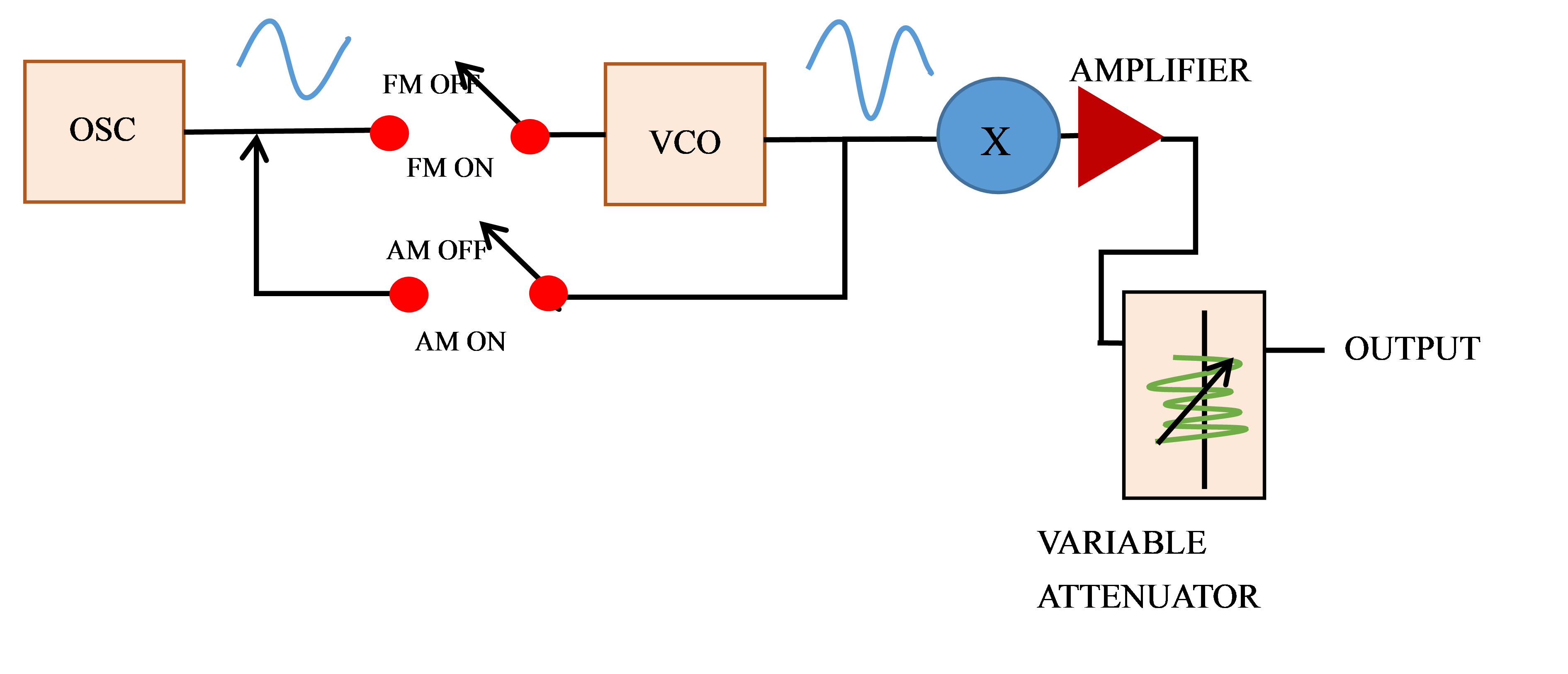
Figure 1. The block diagram of the working principles of a signal generator.
A Voltage-Controlled Oscillator, or VCO, serves as the primary component of the signal generator. The control voltage maintains a direct correlation with the VCO’s frequency. The oscillator’s frequency is determined by the signal applied to its control input. When an audio input signal is applied across the control voltage, the VCO generates a frequency-modulated signal.
The signal generator is often referred to as the source of tone, random, and digital pattern waveforms. The fundamental distinction between a signal generator and an oscillator lies in the fact that a signal generator produces modified output signals in addition to other signals [7]. Initially, when a signal yields unmodulated signals, continuous-height waveforms are generated. Subsequently, complex signals such as square waves, triangle waves, and other modulated signals are produced [7].
The modulator circuit is placed after the VCO to modulate the frequency. This circuit generates the output AM signal, which alters the voltages at the VCO outputs [7]. In general, the oscillator generates a fundamental frequency signal, which is then processed by the waveform generator to achieve the desired output signal’s shape and amplitude. Finally, the signal output amplifier amplifies the output signal before transmitting it to the test instrument [6-8].
3. Applications of Signal Generator
3.1. Communication Field
Signal generators play a crucial role in the communication field by testing and validating the performance of various communication devices and systems, including wireless transceivers, fiber optic links, and satellite communication systems. They provide a stable and reliable source of test signals that simulate diverse communication scenarios, such as Gaussian noise, periodic signals, and pseudo-random binary sequences (PRBS) [9]. These signals are used to assess the performance of communication systems under different conditions, enabling the study of antenna frequency responses, testing receiver sensitivity and linearity, and verifying transmitter performance. Additionally, signal generators are instrumental in ensuring frequency synchronization and timing accuracy within communication systems [6].
3.2. Research Field
Signal generators are essential tools in research and development laboratories for studying the behavior and characteristics of electronic devices, including applications in electronic warfare (EW), radar systems, sonar systems, and spectrum analysis. They aid in the analysis of electronic component frequency responses, performance testing of filters, examination of nonlinear effects in devices, and the execution of fundamental research on signal processing techniques.
3.3. Software Implementation
With advancements in software-defined radio (SDR) [10,11] technology, there has been a proliferation of signal generators, as they can now be implemented using software. SDR platform implementations, such as GNU Radio [12] and MATLAB [13], enable users to generate complex signals, waveforms, and mathematical models through algorithms and dynamically adjust their parameters. This capability facilitates a wide range of activities, from analyzing digital signals and their outcomes to conducting virtual experiments and studies, as well as validating and debugging complex electronic systems before actual implementation. These software-based signal generators are also valuable for testing communication systems and generating complex signals for signal processing algorithms.
4. The Development of the Signal Generator
The development of modern signal generators has witnessed significant advancements in terms of specifications and technology over the years. These advancements have been progressed through technological advancements in areas such as high-speed electronics, precision oscillators, and advanced modulation techniques.
4.1. Specifications of Modern Signal Generator
Modern signal generators have advanced specifications and features that enable them to generate complex signals and wave-forms with high precision [14]. They can generate signals with frequencies up to several GHz, with amplitudes ranging from micro-volts to kilo-volts. Modern signal generators also offer advanced modulation capabilities, allowing users to generate complex wave-forms such as Quadrature Amplitude Modulation and Phase Shift Keying [15].
4.2. Comparison with the Previous Technology
Advancements in technology have led to improved performance, precision, and functionality in modern signal generators. These advancements include enhanced frequency stability, wider bandwidths, lower phase noise, and higher dynamic range, along with more flexible modulation capabilities when compared to earlier generations of signal generators [6,14]. Additionally, modern signal generators can generate more complex waveforms with higher resolution, empowering users to conduct advanced measurements and experiments.
5. Design of Signal Generator Based on FPGA
5.1. Working Principles and Advantages of FPGA
FPGA (Field-Programmable Gate Array) is a type of programmable logic device that can be configured to perform various logic functions after being programmed by users [2]. FPGA based signal generators utilize FPGA chips to generate signals. The FPGA chip is programmed to act as a waveform generator, where mathematical algorithms are implemented to generate different wave-forms such as sine waves, square waves, and triangular waves [2].
The design of a signal generator based on field-programmable gate arrays (FPGA) offers several advantages such as high density, low power consumption, good expand ability, and convenient programming, which makes it widely used in fields such as data processing, communication, image processing, and control [16]. FPGA technology also allows for efficient implementation of complex logic functions and provides a high degree of flexibility, configuration, and fast processing change the wave-forms and other parameters using software commands. Additionally, FPGA based signal generators are cost-effective, as they can be reused for different applications by reconfiguring their logic circuits [16].
5.2. Specific Design
The software aspect of this design is implemented using the VHDL language. Figure 2 shows a design example of signal generator based on FPGA.
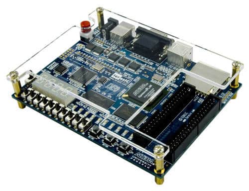
Figure 2. Design of Signal Generator Based on FPGA [16].
The sine wave is generated using the direct lookup table method. All possible values of the sine function are stored in memory, and the corresponding sine function value is indexed through the counter value, resulting in the generation of a sine wave. Square waves are generated using a comparative method. The square wave waveform for a single period is stored in memory, and the corresponding square wave waveform value is indexed through the counter value to produce a square wave. Triangular wave generation employs the recursive method. A triangle wave is generated by continuously calculating the value of the current sample point based on the value of the previous sample point. Saw-tooth wave generation utilizes linear interpolation. Saw-tooth waves are generated by continuously calculating the values of two adjacent sample points and determining the values of the current sample points through linear interpolation [17-19].
5.3. Tests and Results
FPGA-based signal generators have demonstrated excellent results in terms of waveform generation. The signal generator designed with FPGA can produce sine, square, triangle, and saw-tooth waves. To verify the correctness and performance of this design, Frequency Tests are conducted. These tests examine the signal generator’s frequency range and accuracy by varying the counting rate of the counter. The maximum frequency can reach 10 MHz, and the output amplitude can reach 5 V. The output impedance is 50 Ω, and the output port can be selected according to actual needs, either single-ended or differential outputs [18]. This designed signal generator features a straightforward interface and can be controlled by external microcontrollers or computers through serial ports or USB interfaces to adjust the frequency and amplitude of the generated signal.
Table 1 presents data obtained from testing the FPGA-based designed signal generator at various frequencies and amplitudes.
Table 1. Test data of designed signal generator based on FPGA technology [18].
Frequency (Hz) | Amplitude (V) | Output voltage (V) |
1000 | 1 | 1.01 |
10000 | 1 | 1.02 |
100000 | 1 | 1.03 |
1000 | 2 | 2.02 |
10000 | 2 | 2.03 |
100000 | 2 | 2.04 |
5.4. The Problems Solved by FPGA
FPGAs offer excellent expandability and programmability, effectively addressing the challenges associated with upgrading and expanding traditional signal generators [17,18]. FPGAs can be readily programmed to generate various waveforms and frequencies of signals to suit different application scenarios. Moreover, the utilization of FPGA technology resolves several issues inherent in traditional signal generator designs, such as inflexibility, limitations in waveform generation capabilities, and subpar performance.
FPGA-based signal generators find extensive use in high-speed data communication systems. They play a pivotal role in generating complex waveforms for testing high-speed interfaces and circuits in contemporary applications [19].
6. Conclusion
In conclusion, signal generators play a pivotal role in the testing and validation of electronic devices across various fields, including communication, research, and software implementation. FPGA-based signal generators offer several notable advantages, including high speed, accuracy, programmability, and real-time signal processing capabilities. This paper has provided a comprehensive study of signal generators and their applications, with a particular focus on the design of an FPGA-based signal generator. The primary findings suggest that modern FPGA-based signal generators outperform traditional counterparts in terms of precision, speed, programmability, and real-time processing capabilities.
The future of these modern generators holds significant promise, with a wide range of potential applications and technological advancements. Their numerous advantages are poised to play an essential role in electronic testing. However, it’s important to acknowledge that there are still limitations, such as cost, power consumption, and the complexity of FPGA programming, which require attention in future research.
Additionally, it’s worth noting that there are some limitations in the data collection process, primarily relying on internet sources that may vary in reliability. Furthermore, the use of English, not being my native language, may lead to some clarity issues in explanations and limitations in source availability.
References
[1]. Hee Jung Yang, et al. Implementation of DDS Chirp Signal Generator on FPGA. 1 Oct. 2014, https://doi.org/10.1109/ictc.2014.6983343. Accessed 2 Sept. 2023.
[2]. Chua, Ming Yam, and Voon Chet Koo. “FPGA-BASED CHIRP GENERATOR for HIGH RESOLUTION UAV SAR.” Progress in Electromagnetics Research, vol. 99, 2009, pp. 71–88, https://doi.org/10.2528/pier09100301. Accessed 11 May 2023.
[3]. Chua, Ming Yam, and Voon Chet Koo. “FPGA-BASED CHIRP GENERATOR for HIGH RESOLUTION UAV SAR.” Progress in Electromagnetics Research, vol. 99, 2009, pp. 71–88, https://doi.org/10.2528/pier09100301. Accessed 11 May 2023.
[4]. Firmansyah, Iman, and Yoshiki Yamaguchi. “FPGA-Based Implementation of a Chirp Signal Generator Using an OpenCL Design.” Microprocessors and Microsystems, vol. 77, Sept. 2020, p. 103199, https://doi.org/10.1016/j.micpro.2020.103199. Accessed 27 Mar. 2022.
[5]. T, Archana. “What Is a Signal Generator? - Definition & Explanation.” Circuit Globe, 21 June 2017, circuitglobe.com/signal-generator.html. Accessed 2 Sept. 2023.
[6]. Chauhan, Yamini. “Signal Generator | Electronics.” Encyclopedia Britannica, 25 Feb. 2013, www.britannica.com/technology/signal-generator.
[7]. https://www.facebook.com/electrical4u. “Signal Generator | Electrical4U.” Electrical4U, 24 Feb. 2012, www.electrical4u.com/signal-generator/.
[8]. Swift, Simon, et al. “The Inner Workings of a Quorum Sensing Signal Generator.” Trends inMicrobiology,vol.4,no.12,1Dec.1996,pp.463–465,https://doi.org/10.1016/s0966-842x(97)82904-6. Accessed 2 Sept. 2023.
[9]. Basics of Vector Signal Generators Part 1: Real-Time Waveform Generation Mode.
[10]. Pini, Art. “Learn the Fundamentals of Software-Defined Radio and How to Use It with a Low-Cost Module.” DigiKey, DigiKey’s North American Editors, 30 June 2020, www.digikey.com/en/articles/learn-the-fundamentals-of-software-defined-radio. Accessed 2 Sept. 2023.
[11]. “Introductionto Software-Defined Radio.” Allaboutcircuits.com, Feb.2017, www.allaboutcircuits.com/technical-articles/introduction-to-software-defined-radio/.
[12]. “What Is GNU Radio? GNU Radio.” Gnuradio.org, 2019, wiki.gnuradio.org/index.php/What_is_GNU_Radio%3F.
[13]. MathWorks. “MATLAB-MathWorks.” Mathworks.com, 2019, www.mathworks.com/products/matlab.html.
[14]. Hsu, Eric. “Introduction to the Signal Generator.” Www.keysight.com, 31 Oct. 2018, www.keysight.com/blogs/tech/rfmw/2018/10/30/introduction-to-the-signal-generator#:~:text=Key%20Specifications%20of%20a%20Signal%20Generator%201%20Frequency. Accessed 2 Sept. 2023.
[15]. Aydar, Ali. “Digital Communication - Phase Shift Keying - Tutorialspoint.” Tutorialspoint.com, 2020, www.tutorialspoint.com/digital_communication/digital_communication_phase_shift_keying.htm.
Cite this article
Liu,Y. (2024). The signal generator: A critical analysis of its basic principles, applications, and development. Applied and Computational Engineering,42,27-33.
Data availability
The datasets used and/or analyzed during the current study will be available from the authors upon reasonable request.
Disclaimer/Publisher's Note
The statements, opinions and data contained in all publications are solely those of the individual author(s) and contributor(s) and not of EWA Publishing and/or the editor(s). EWA Publishing and/or the editor(s) disclaim responsibility for any injury to people or property resulting from any ideas, methods, instructions or products referred to in the content.
About volume
Volume title: Proceedings of the 2023 International Conference on Machine Learning and Automation
© 2024 by the author(s). Licensee EWA Publishing, Oxford, UK. This article is an open access article distributed under the terms and
conditions of the Creative Commons Attribution (CC BY) license. Authors who
publish this series agree to the following terms:
1. Authors retain copyright and grant the series right of first publication with the work simultaneously licensed under a Creative Commons
Attribution License that allows others to share the work with an acknowledgment of the work's authorship and initial publication in this
series.
2. Authors are able to enter into separate, additional contractual arrangements for the non-exclusive distribution of the series's published
version of the work (e.g., post it to an institutional repository or publish it in a book), with an acknowledgment of its initial
publication in this series.
3. Authors are permitted and encouraged to post their work online (e.g., in institutional repositories or on their website) prior to and
during the submission process, as it can lead to productive exchanges, as well as earlier and greater citation of published work (See
Open access policy for details).
References
[1]. Hee Jung Yang, et al. Implementation of DDS Chirp Signal Generator on FPGA. 1 Oct. 2014, https://doi.org/10.1109/ictc.2014.6983343. Accessed 2 Sept. 2023.
[2]. Chua, Ming Yam, and Voon Chet Koo. “FPGA-BASED CHIRP GENERATOR for HIGH RESOLUTION UAV SAR.” Progress in Electromagnetics Research, vol. 99, 2009, pp. 71–88, https://doi.org/10.2528/pier09100301. Accessed 11 May 2023.
[3]. Chua, Ming Yam, and Voon Chet Koo. “FPGA-BASED CHIRP GENERATOR for HIGH RESOLUTION UAV SAR.” Progress in Electromagnetics Research, vol. 99, 2009, pp. 71–88, https://doi.org/10.2528/pier09100301. Accessed 11 May 2023.
[4]. Firmansyah, Iman, and Yoshiki Yamaguchi. “FPGA-Based Implementation of a Chirp Signal Generator Using an OpenCL Design.” Microprocessors and Microsystems, vol. 77, Sept. 2020, p. 103199, https://doi.org/10.1016/j.micpro.2020.103199. Accessed 27 Mar. 2022.
[5]. T, Archana. “What Is a Signal Generator? - Definition & Explanation.” Circuit Globe, 21 June 2017, circuitglobe.com/signal-generator.html. Accessed 2 Sept. 2023.
[6]. Chauhan, Yamini. “Signal Generator | Electronics.” Encyclopedia Britannica, 25 Feb. 2013, www.britannica.com/technology/signal-generator.
[7]. https://www.facebook.com/electrical4u. “Signal Generator | Electrical4U.” Electrical4U, 24 Feb. 2012, www.electrical4u.com/signal-generator/.
[8]. Swift, Simon, et al. “The Inner Workings of a Quorum Sensing Signal Generator.” Trends inMicrobiology,vol.4,no.12,1Dec.1996,pp.463–465,https://doi.org/10.1016/s0966-842x(97)82904-6. Accessed 2 Sept. 2023.
[9]. Basics of Vector Signal Generators Part 1: Real-Time Waveform Generation Mode.
[10]. Pini, Art. “Learn the Fundamentals of Software-Defined Radio and How to Use It with a Low-Cost Module.” DigiKey, DigiKey’s North American Editors, 30 June 2020, www.digikey.com/en/articles/learn-the-fundamentals-of-software-defined-radio. Accessed 2 Sept. 2023.
[11]. “Introductionto Software-Defined Radio.” Allaboutcircuits.com, Feb.2017, www.allaboutcircuits.com/technical-articles/introduction-to-software-defined-radio/.
[12]. “What Is GNU Radio? GNU Radio.” Gnuradio.org, 2019, wiki.gnuradio.org/index.php/What_is_GNU_Radio%3F.
[13]. MathWorks. “MATLAB-MathWorks.” Mathworks.com, 2019, www.mathworks.com/products/matlab.html.
[14]. Hsu, Eric. “Introduction to the Signal Generator.” Www.keysight.com, 31 Oct. 2018, www.keysight.com/blogs/tech/rfmw/2018/10/30/introduction-to-the-signal-generator#:~:text=Key%20Specifications%20of%20a%20Signal%20Generator%201%20Frequency. Accessed 2 Sept. 2023.
[15]. Aydar, Ali. “Digital Communication - Phase Shift Keying - Tutorialspoint.” Tutorialspoint.com, 2020, www.tutorialspoint.com/digital_communication/digital_communication_phase_shift_keying.htm.