


1. Introduction
As science and technology rapidly develop while the industries improve, traditional industries have been unable to meet the existing market. New technologies were put into use which has the corresponding environment and needs. High-tech products which feature automation and control to improve convenience and safety, are used in the production streamline to reduce manpower and cost while improving production efficiency. In the workshop, the robot arm can help workers pick, sort and stack on the assembly streamline, increasing the efficiency and reducing the risk to workers.
Traditional robotic arms in the past often carried out simple and repetitive single actions and could not achieve the goal of so-called intelligent automation, which can automatically manipulate, and move while catching the target for putting it in the targeting position. To further improve the automation characteristics of the robot arm, more functional components have been added to the robot arm to ensure that it can be used in more environments. At present, to ensure that the robot arm meets more needs and can make more automatic choices about the environment, vision sensors are added to the robot arm to cooperate with the use of the robot arm to achieve the purpose of visual recognition and grasp.
This article will mainly discuss intelligent object recognition and grasping robot arms. The vision sensor is a crucial component of this kind of robot arm. For the visual recognition robot arm, the recognition model is the core tech going to be discussed. There are two types of models, the CNN model and the transformer model and this article will explain their main theories. They are two different neural networks. CNN model is one type of neural model for deep learning, which is based on convolution, padding, and pooling. The data is fully connected to the neural network to achieve the goal of obtaining the features of the photos. CNN model is an algorithm commonly used for picture processing. For the transformer model, it focuses on increasing the speed of the model training by using the mechanism of attention. This model is a deep-learning model fully based on the self-attention mechanism, which is suitable for parallel computation. Then, the self-attention mechanism will be discussed briefly. Based on two different frameworks, different self-attention models are created for visual sensors to capture image features, capture images, and grab objects. Specifically, channel attention is used in the CNN model. This helps the model to build the channels explicitly. Meanwhile, for the transformer model, self-attention makes the dependencies of long-range become possible. Next, the article will discuss how sensors operate through the neural network architecture CNN model and transformer model, analysing their main features and advantages, including feature extraction local awareness for the CNN model, and self-attention and parallel computation for the transformer model [1]. Apart from that, the disadvantage will also be discussed, involving the possibility of losing the information and data in the pooling layer for the CNN model, and insufficient local feature acquisition ability for the transformer model compared with the CNN model [2].
This article will also focus on how the robot uses the sensor can achieve the grabbing, in the way that the model extracts 2D and 3D feature information through attitude estimation and a visual servo system. The position of the object is recognized, and the coordinate of the object is sent to the machine. Then, the information is transformed as feedback to make the robot arm respond, which is controlled to achieve the grabbing.
2. Background
There are two prerequisites needed for the visual recognition robotic arm to grab things, which are navigation and visual recognition position.
The robotic arm has two types of navigation methods based on the environment; one is based on a planned moving path in the known environment. The manual ways of setting the path and series action are only suitable for the fixed position object. It repeats the action and motion, affected by the environment. Meanwhile, the other method is based on the SLAM (Simulation, Localization and Mapping) algorithm method to build the appropriate path in an unknown environment, used with visual sensor and lidar to achieve the goals. Based on the deep-learning model, the robotic arm can operate automatically [3].
The aim of the visual recognition grabbing robotic arm is to recognize the object and grab it then place it into the corresponding position. To achieve the goal, the way to achieve it can be divided into several small actions. The visual sensor first recognizes the object, converting the image of the object from RGB space to HSV space, followed by obtaining the colour of the image. The image then is binarized, while being operated. Finally, the image of the object outline is obtained [4].
2.1. The CNN model
The algorithm in the CNN model is deep learning. CNN model is a model that generates graphs through pooling and convolutional stacking. The main processing way is separated into several parts, including convolution, pooling, and padding. Before the computation, the image is first separated into many small units with different digits. After convolution computation with the kernel, the result is obtained, followed by a slide into the corresponding stride and repeat the process again. The result is padded with zero around the image, which is the necessary process for increasing the matrix image size so that the data or the information cannot be lost in the convolution process, while the sizes of the image before and after the computation are the same. Next, the matrix image is processed with the pooling layer, which can be separated into two types of pooling layers: max pooling layer and average pooling. layer. The image is filtered with these three filters to complete one cycle of the process [5].
|
Figure 1. The CNN model illustration [5]. |
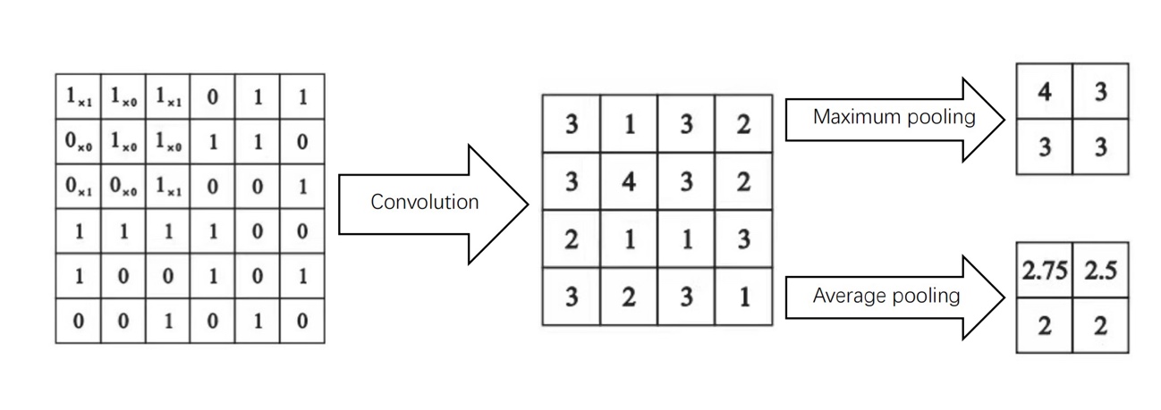
CNN model can extract the spatial image feature targeted, and also the translation image invariance can be adapted suitably. At the same time, the shared weights and local joints reduce the convolution greatly. Apart from that, as mentioned before, the pooling layer simplifies the data of output after the convolution layer which reduces the number of neurons. The advantages of the CNN model of better feature extraction, fewer joints and parameter that provides the opportunity for faster speed computation and deeper learning feature [5].
However, the feature of translation image invariance can also be a disadvantage since it might not activate the neurons. Apart from that, in the pooling layer, as mentioned above, the important information and connections between the whole part and the minor part might be lost.
The transformer model is the neural deep-learning model that is fully based on the self-attention mechanism. This model can be trained for the goal of increasing speed. The model basically can be assumed as the mechanism composed of three elements: input, transformer, and output, while the transformer includes encoder and decoder. The encoder processes and codes the data, which includes the self-attention layer to compute the information and data. Meanwhile, the decoder’s role is decoding the data [6].
2.2. The transformer model
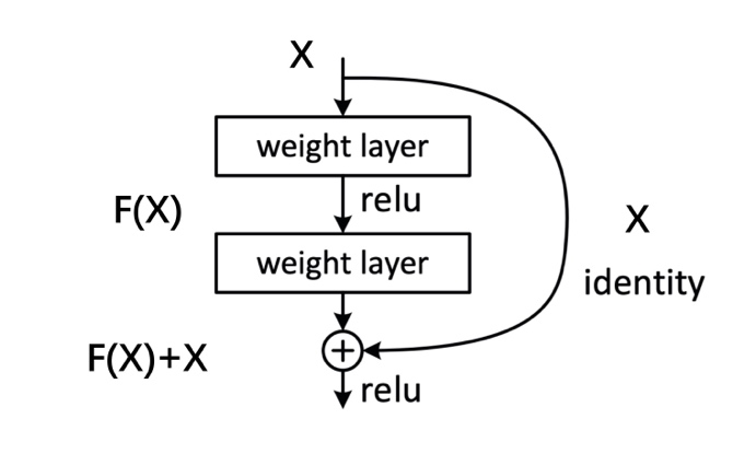
The transformer model has an important part which is ResNet. The role of the ResNet is to divide the data into two parts. One is exchanged and another part is sent to the next layer directly, which is combined as the input for the next layer [7]. The ResNet contains two layers, and the structure of the ResNet can be expressed by the formula below:
\( g(x)=f(x)+x \) (1)
The variable \( f(x) \) is called the residual function. The aim is to make \( f(x) \) as small as possible by learning, therefore deep learning can be achieved while the data cannot be lost.
|
Figure 2. The Transformer Model structure [8]. |
The transformer model breaks the limited receptive field of CNN, while it can directly predict the categories and detect the box. In addition, the transformation can use the full content of the context information, while the global image dependencies relationship can be built by using this model. It has a big potential for image segmentation, object detection and graph category function, which can be used in multiple visual related tasks.
However, due to the initial stage of this model, the problem of the high amount of computation and the loss of important data and information still exists. Besides, this model lacks the capability of local feature extraction, which is also a defect of this model.
As the article mentioned above, the CNN model and the transformer model are the two models commonly used for the visual recognition model. They are also what we call the ‘self-attention model’. The neural learning model is based on this model.
The self-attention mechanism aims at contributing different attention weights to different parts of input so that the learning model performance can be improved due to the different attention weight distribution model learning emphasis on key information. To some extent, this reduces the amount of the computation [9].
The channel self-attention mechanism used by the CNN model extracts the local and global features at first. The standard of the feature mapping of channel self-attention is based on the channel weight value, which represents the value of weight relating to the degree of relevance. By using this mechanism, the dependence of the channel can be reduced, while the strong useful features and delete unrelated information.
The transformer model itself is created based on the self-attention mechanism. There are multiple self-attention layers in the encoder and a middle cross-attention layer in the decoder.
Both the CNN model and the transformer model are learning models. Since the brief process of the learning model is separated the learning into many different blocks, the neural augmentation learning model decoupled states are \( ds(t) \) , constraint force, and input. The constraint force is considered as \( {g_{c}}(t) \) , and the input is partial state measurement, stating as \( \bar{ds}(t) \) . The difference between the augmented \( ds(t) +∆ds(t) \) and \( \bar{ds}(t) \) .
For the transformer model, the constant matrix S is introduced, which chooses and converts the full-state quantities, therefore the partial measurements and states difference can be found and compared. When the loss function is considered, comparing \( S(ds(t)+∆ds(t)) \) to \( \bar{ds} \) Before comparing, the original state is converted into the subtracting form which is \( ∆\bar{ds}(t)= \bar{ds}-Sds(t) \) . Finally, the state that should be compared is \( ∆\bar{ds}(t)= \bar{ds}-Sds(t) \) to \( S∆ds(t) \) [10].
At present, for the vision-sensing robot arm, the CNN model lacks global observation and only has a good local judgment for important features. Although the ViT framework based on the transformer model abandons the step of big data acquisition, the efficiency of overall image feature collection has been greatly improved, but there are still problems in image stretching [2]. This paper will discuss how the neural network connects with the robotic arm and visual sensor to achieve visual recognition and grab the object.
3. Method
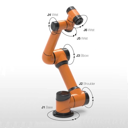
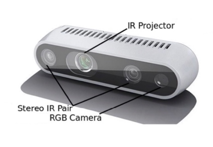
The 6 DOF robotic arm is installed with the eye-in-hand camera matched with a neural network. The depth camera with a global shutter sensor is used which has big advantages when used in low light and wide field-of-view scenes. The small volume depth camera is composed of an IR projector, a Colour camera (Colour sensor), and two IR Stereo cameras, while the depth photo is obtained by the two sides Infrared Camera [11].
|
| |
Figure 3. 6 DOF robotic arm. The figure is cited from https://www.gsautomatic.com/automatic-6dof-industrial-robotic-arm-10kg-payload-cobot-robot-collaborative-robot/. | Figure 4. The stereo camera [11]. |
It is basically an inversion-free image-based visual servoing system. The system uses a Linux operation system and matches with the ROS system to operate and control the robotic arm, end grabber and camera.
The camera and deep-learning method can be used for identifying and locating the object. The system is trained before being used so that it can operate correctly [12]. The process of optimal training is shown below:
Algorithm: Optimal training |
Input: Source domain data: \( { D_{s}}=\lbrace ({X_{S,n}}, {y_{S,n}})\rbrace _{n=1}^{{N_{s}}} \) , Target domain data: \( {D_{T}}=\lbrace {X_{T,n}}\rbrace _{n=1}^{{N_{T}}} \) Output: Deep neural networks parameters \( W \) , Target domain pseudo-tag \( \widetilde{{Y_{T}}} \) 1 The parameters \( W \) of the domain adaptive network model are initialized using the network parameters learned from the ImageNet dataset 2 Use source domain data \( {D_{s}} \) to fine-tune the network model and preliminarily optimize \( W \) 3 Set the pseudo-label \( \widetilde{{Y_{T}}} \) of the target domain data through the fine-tuned network model, set the total number of training steps \( V \) , and initialize the number of training steps \( v: v=0 \) 4 repeat 5 Score by false label classification \( \lbrace {S_{T,n,max}}\rbrace _{n=1}^{{N_{T}}} \) , the target domain sample \( {D_{T}} \) is divided into three groups: \( {D_{TH}}, {D_{TM}}, {and D_{TL}} \) 6 Construct the label noise robust regression function \( {l_{TH}}(W),{l_{TM}}(W), and {l_{TL}}(W) \) 7 Leverage source domain data \( \lbrace ({X_{S,n}},{y_{S,n}})\rbrace _{n=1}^{{N_{s}}} \) and data with target domain \( \lbrace ({X_{T,n}}, {\widetilde{y}_{T,n}})\rbrace _{n=1}^{{N_{T}}} \) , minimize the global optimization function \( {L_{G}}(W) \) , update neural network parameters W \( {W^{v+1}}←{W^{v}}- η{τ^{v+1}} \) \( {τ^{v+1}}= κ{τ^{v}}+(1-κ)\frac{d{L_{G}}(W)}{dZ}∙\frac{∂Z}{∂W} \) 8 The pseudo-label \( \widetilde{{Y_{T}}} \) of source domain data \( {D_{T}}= \lbrace {X_{T,n}}\rbrace _{n=1}^{{N_{T}}} \) is updated by using the current domain adaptive recognition model 9 \( v = v + 1 \) 10 until: \( \widetilde{Y_{T}^{v}}=\widetilde{Y_{T}^{v+1}} or v \gt V \) 11 return: \( W, \widetilde{{Y_{T}}}=\widetilde{Y_{T}^{v}} \) |
The camera will be matched with the system so it can load the corresponding appropriate model for the object. The algorithm helps the robotic arm to perceive the pose of all objects, and 3 DOF physical pose scale of the object will be obtained, including the coordinate of the centre of the object (x,y), and the orientation \( θ \) . The specific grabbing decision is made before the robotic arm moves to the detected object. The centre of the object is located, and the end grabber will move and adjust, rotating to the suitable angle, then grab it [11]. The position of the object is related to the camera on the robotic arms. The relationship between the coordinates of the camera and the object can be expressed as below:
Image coordinate system (x,y) to pixel coordinate system (u,v):
\( u=\frac{x}{dx}+{u_{0}}, v=\frac{y}{dy}+{v_{0}} \) (2)
Convert to the homogeneous coordinates:
\( [\begin{matrix}u \\ v \\ 1 \\ \end{matrix}]=[\begin{matrix}\frac{1}{dx} & 0 & {u_{0}} \\ 0 & \frac{1}{dy} & {v_{0}} \\ 0 & 0 & 1 \\ \end{matrix}][\begin{matrix}x \\ y \\ 1 \\ \end{matrix}], \) (3)
where \( {u_{0}} \) and \( {v_{0}} \) is the centre of the graph, while \( dx \) and \( dy \) are pixel size.
Therefore, the coordinate of the camera (a,b,c) to image coordinare (x,y):
\( \frac{x}{f}=\frac{a}{c}, \frac{y}{f}=\frac{b}{c} \) (4)
Convert to the homogeneous coordinare:
\( c[\begin{matrix}x \\ y \\ 1 \\ \end{matrix}]=[\begin{matrix}f & 0 & 0 & 0 \\ 0 & f & 0 & 0 \\ 0 & 0 & 1 & 0 \\ \end{matrix}][\begin{matrix}a \\ b \\ c \\ 1 \\ \end{matrix}] \) (5)
where c is the scale factor, and \( f \) is the camera focal length.
The world coordinate (A, B, C) to camera coordinate (a, b, c):
\( [\begin{matrix}a \\ b \\ c \\ 1 \\ \end{matrix}]=[\begin{matrix}M & N \\ O & 1 \\ \end{matrix}][\begin{matrix}A \\ B \\ C \\ 1 \\ \end{matrix}], \) (6)
where \( M \) is 3 by 3 rotation matrix, and \( T \) is 3 by 1 translation vector.
Combine the above expression to obtain:
\( c[\begin{matrix}u \\ v \\ 1 \\ \end{matrix}]=[\begin{matrix}\frac{1}{dx} & 0 & {u_{0}} \\ 0 & \frac{1}{dy} & {v_{0}} \\ 0 & 0 & 1 \\ \end{matrix}][\begin{matrix}f & 0 & 0 & 0 \\ 0 & f & 0 & 0 \\ 0 & 0 & 1 & 0 \\ \end{matrix}][\begin{matrix}M & N \\ O & 1 \\ \end{matrix}][\begin{matrix}A \\ B \\ C \\ 1 \\ \end{matrix}] \) (7)
\( c[\begin{matrix}u \\ v \\ 1 \\ \end{matrix}]=[\begin{matrix}{f_{x}} & 0 & {u_{0}} & 0 \\ 0 & {f_{y}} & {v_{0}} & 0 \\ 0 & 0 & 1 & 0 \\ \end{matrix}][\begin{matrix}M & N \\ O & 1 \\ \end{matrix}][\begin{matrix}A \\ B \\ C \\ 1 \\ \end{matrix}] \) (8)
where \( {f_{x}}=\frac{f}{dx} \) is the normalized focal length on the x-axis, \( {f_{y}}=\frac{f}{dy} \) is the normalized focal length on the y-axis.
The internal parameter of the camera is \( [\begin{matrix}{f_{x}} & 0 & {u_{0}} & 0 \\ 0 & {f_{y}} & {v_{0}} & 0 \\ 0 & 0 & 1 & 0 \\ \end{matrix}] \) , and the external parameter of the camera is \( [\begin{matrix}M & N \\ O & 1 \\ \end{matrix}] \) [11].
The robotic arm moves to the corresponding position while the camera is turned on. The control instruction is sent to the robotic arm, and the distance between the current position of the robot and the position of the target object is calculated after the movement. After the position and the coordinate of the object is obtained, the grasping decision is needed for the robotic arm so that the arm can operate and grab the object. When the distance is less than a certain threshold, the grasping action is performed to complete the grasping of the target object [12].
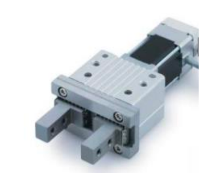
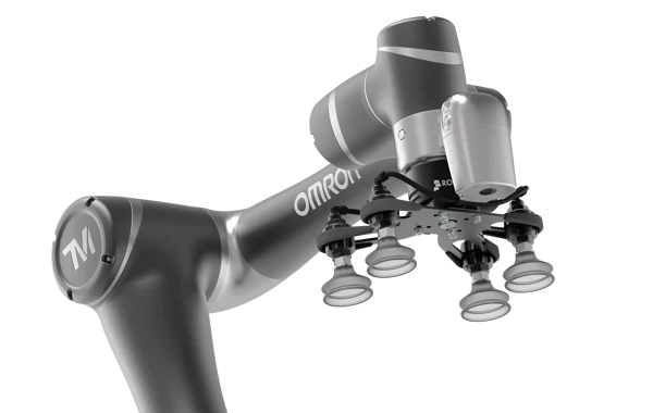
The end of the robotic arm is installed with the grabbing part, which can be the two-fingered ending grabber or the exhaust vacuum suction cup grabber.
|
| |
Figure 5. The two-fingered ending grabber [14]. | Figure 6. The exhaust vacuum suction cup grabber. The figure is cited from https://blog.robotiq.com/11-helpful-questions-about-machine-tending-with-vacuum-grippers. |
For the image feature extraction, the system segments the graph while separating it from the background so that the capture angle can be obtained. The object is selected in the detected rectangle area and the outer area is assumed as the background, therefore the image can be separated into the foreground and background. The GMM (Gaussian Mixture Model) is used for modelling. The image is composed of pixels, and each one can be considered as the connection between the virtual edge and the surrounding pixels. The edge between the nearby pixels can be cut if the type of pixels of the image are not the same type. Therefore, the object can be extracted as well as the features in the selected area [3].
For the colour detection design, the image also be extracted, and the picture is transferred from RGB space to HSV space. The position of the camera base and the robot arm is always not fixed, which will increase the calculation amount of hand-eye calibration. The object is placed and fixed in the field of camera view, which controls the robot arm and drives the camera to shoot the object many times to get the 3D image, coordinate, and position. Finally, the transformation matrix of the camera relative to the claw of the robot arm is calculated [4].
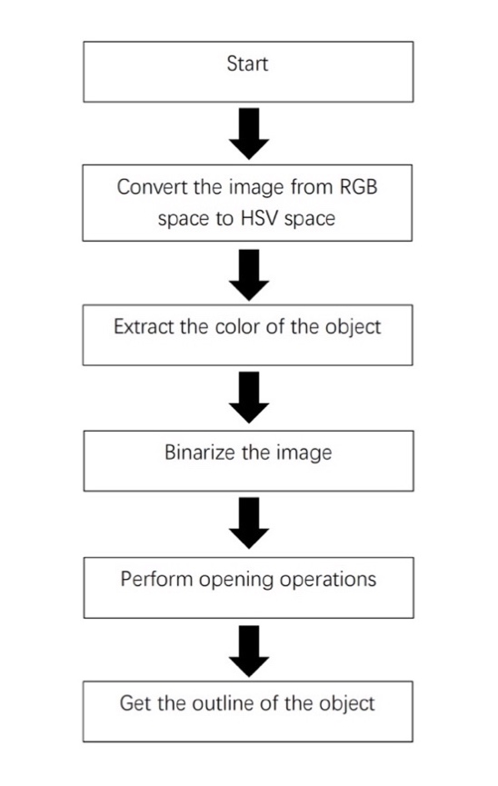
Figure 7. The flow chart of color detection [4]. |
For the CNN model, to solve the problem of the lack of the global observation, the self-attention mechanism is used to improve the original spatial convolution and enhance the coding ability of CNN for global information.
For the transformer model, the ViT is used, and since it has a self-attention mechanism, it has a high amount of computation. When processing the high-resolution image, the memory required by ViT will be squared growth. To solve this problem, the length of the computed sequence like pooling tokens should be reduced, using sparse attention or localized attention to improve efficiency and reduce computational complexity [2].
4. Result
The designed visual recognition-grabbing robotic arm is tested for its feasibility. In the series of experiments, the coordinate conversion error experiments are taken to test the feasibility of the conversion between the calculated coordinate and the actual coordinate with respect to the error. Then, since the training is taken for the deep-learning model to learn for the target of grabbing, the result of the test of the training is shown in the form of the loss. Therefore, the result of the loss is going to be shown and the trend can be predicted to verify the feasibility of the deep-learning model function for the robotic arms grabbing. Next, the grabbing test is taken and proportional integration feedforward to see the tracking distance result and the error and determine the function of tracking is operational or not.
For the experiment, the coordinate conversion error experiment is taken for testing to check the error of the calculated coordinate and actual coordinate. The maximum error of the x-axis is 0.59cm, and 0.6cm for the y-axis.
Table1. Coordinate conversion error [4]. | ||||
Number | Calculated coordinate | Actual coordinate | Error of X-axis | Error of Y-axis |
1 | (-13.90, 19.40) | (-14.20) | 0.1 | -0.6 |
2 | (-0.04, 16.14) | (0.16) | -0.04 | 0.14 |
3 | (-1.85, 12.07) | (-2.12) | 0.15 | 0.07 |
4 | (1.93, 16.19) | (2.16) | -0.07 | 0.19 |
5 | (3.28, 11.20) | (3.11) | 0.28 | 0.2 |
6 | (-8.60, 11.00) | (-9.11) | -0.4 | 0 |
7 | (11.59, 7.38) | (11.7) | 0.59 | 0.38 |
8 | (9.30, 12.32) | (9.12) | 0.3 | 0.32 |
9 | (-8.75, 16.70) | (-9.17) | 0.25 | -0.3 |
10 | (-5.69,8.91) | (-6.9) | 0.31 | -0.09 |
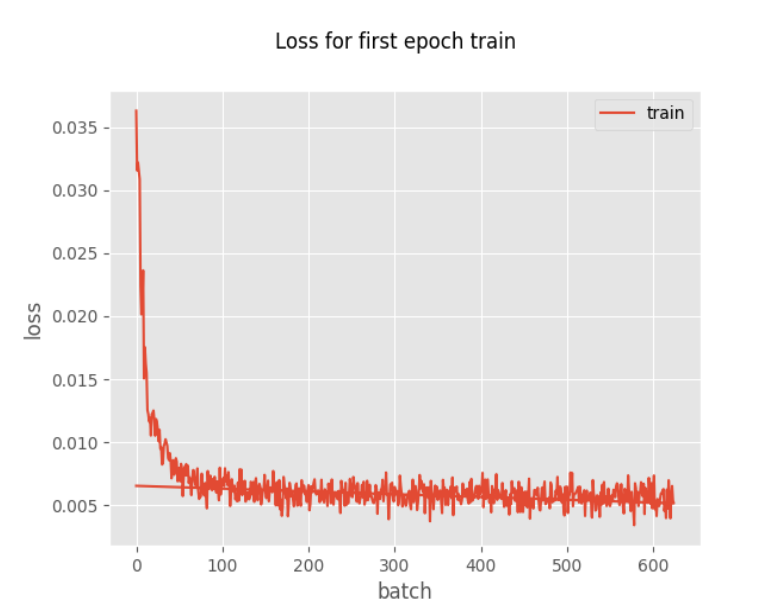
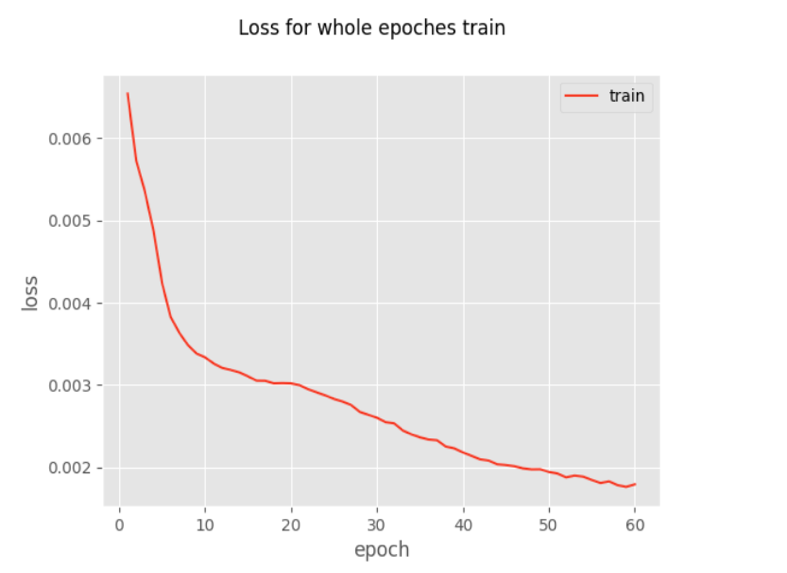
Then, the deep-learning training is taken for the testing and also training the robotic arms for grabbing the object. The result is shown in the form of a loss. As the testing graph shows, the loss decreases rapidly with the increasing number of the epochs train. At the end, the train tends to be small and stable, showing as the horizontal stable line.
|
| |
Figure 8. Loss for first epoch train [13]. | Figure 9. Loss for whole epochs train [13]. |
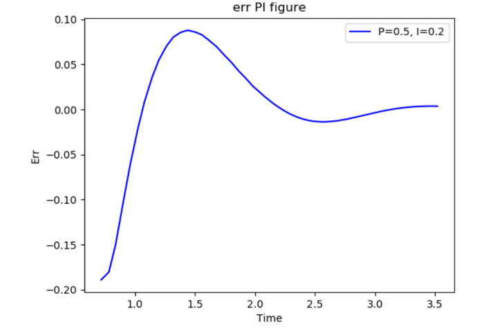
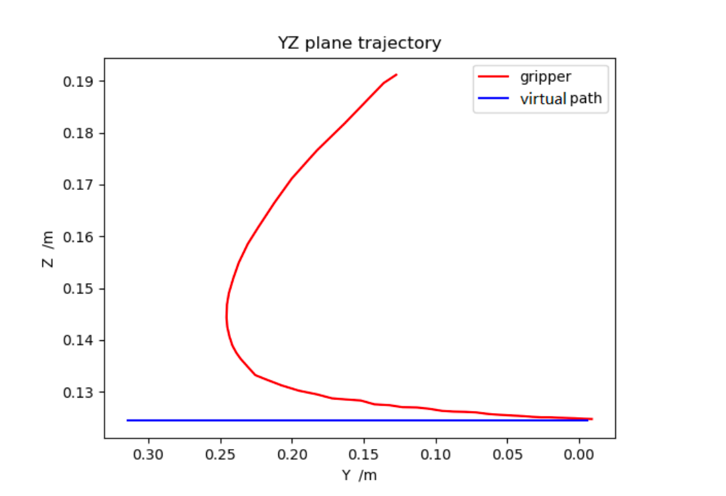
Start recording the data needed to plot the error curve when the proportional integral is enabled until the tracking process is complete. After adding the proportional integration feedforward, the robot can continuously shorten the tracking distance in the negative direction of the Y-axis until it keeps up with the target object moving at a constant velocity in the negative direction of the Y-axis [13].
|
| |
Figure 10. Y-axis position error curve after proportional integral feedforward [13]. | Figure 11. YZ plane gripper and virtual target pose curve [13]. |
The theory of the two types of the neural network is introduced, and the method of the visual recognition robotic arms is explained. In the experiments, the experiments show the visual recognition robotic arm is feasible machine for the target of grabbing object. The errors are in the control range, and the operation is feasible. The overall system for the robotic arm is appropriate and useful. For the visual recognition grabbing robotic arms industry, the future become more promising [14][15].
References
[1]. Ashish V, Noam S, Niki P, Jakob U, Llion J, Aidan G, Lukasz K and Illia P June 20 Attention Is All You Need 10.48550/arXiv.1706.03762
[2]. Li Y, H, Qinbin H, Zihang J, Jiashi F and Shuichen Y May 2023 VOLO: Vision Outlooker for Visual Recognition IEEE Transactions on Pattern Analysis and Machine Intelligence vol 45, no 5, pp 6575-6586
[3]. Zhen L, Benlian X, Di W, Kang Z, Mingli L and Jinliang C October 2021 A Mobile Robotic Arm Grasping System with Autonomous Navigation and Object Detection International Conference on Control, Automation and Information Sciences (ICCAIS) pp 543-548
[4]. Yuming L, Qi Zhang, Xiao L, Ziyi L and Xiwei Zhang 2021 Automatic grasping of 3-DOF robotic arm based on visual feedback 2021 International Symposium on Computer Technology and Information Science (ISCTIS) pp 79-85
[5]. Rong Z, Weiping L and Tong M 2018 Review of Deep Learning Information and Control vol 47 pp 385-397
[6]. Jifang H 2022 Review of Transformer research status Information system engineering vol 2 pp 4
[7]. Wentao Z and Ting Z July 2023 Convolutional neural network image recognition based on transfer learning Modern Information Technology Vol 7 No 14
[8]. Kaiming H, Xiangyu Z, Shaoqing R and Jian S December 2015 Deep Residual Learning for Image Recognition Computer Vision and Pattern Recognition arXiv:1512.03385
[9]. Chong C, Tao W, Chao L , Yuxin L and Lianglun C 2023 Lightweight Convolutional Transformers Enhanced Meta-Learning for Compound Fault Diagnosis of Industrial Robot Transactions on Instrumentation and Measurement vol 72 pp 1-12
[10]. Agon S, Espen K, Christian S, Naveen K, Markus G and Moritz B June 2023 Transformer-Based Neural Augmentation of Robot Simulation Representations Robotics and Automation Letters vol 8 no 6 pp 3748-3755
[11]. Development of a service robot arm grasping object system based on vision. Xia,W.Xia W 2021 Development of a service robot arm grasping object system based on vision Information technology Heilongjiang University vol 9
[12]. Guangbing W May 2021 Research on Multi-object Grasping Detection For Robots Based on Domain Adaptation Information technology Harbin Institute of Technology vol 2
[13]. Chen Y 2022 Research on Robot Dynamic Target Tracking Control based on Visual Servoing Control science and engineering Dalian University of Technology vol 2
[14]. Chen J, Xie Z and Dames P 2022 The semantic PHD filter for multi-class target tracking: From theory to practice Robotics and Autonomous Systems 149 103947.
[15]. Chen J and Dames P 2022 Multi-class target tracking using the semantic phd filter In Robotics Research: The 19th International Symposium ISRR p 526-541
Cite this article
Wu,Y. (2024). Research on grasping model based on visual recognition robot arm. Applied and Computational Engineering,41,11-21.
Data availability
The datasets used and/or analyzed during the current study will be available from the authors upon reasonable request.
Disclaimer/Publisher's Note
The statements, opinions and data contained in all publications are solely those of the individual author(s) and contributor(s) and not of EWA Publishing and/or the editor(s). EWA Publishing and/or the editor(s) disclaim responsibility for any injury to people or property resulting from any ideas, methods, instructions or products referred to in the content.
About volume
Volume title: Proceedings of the 2023 International Conference on Machine Learning and Automation
© 2024 by the author(s). Licensee EWA Publishing, Oxford, UK. This article is an open access article distributed under the terms and
conditions of the Creative Commons Attribution (CC BY) license. Authors who
publish this series agree to the following terms:
1. Authors retain copyright and grant the series right of first publication with the work simultaneously licensed under a Creative Commons
Attribution License that allows others to share the work with an acknowledgment of the work's authorship and initial publication in this
series.
2. Authors are able to enter into separate, additional contractual arrangements for the non-exclusive distribution of the series's published
version of the work (e.g., post it to an institutional repository or publish it in a book), with an acknowledgment of its initial
publication in this series.
3. Authors are permitted and encouraged to post their work online (e.g., in institutional repositories or on their website) prior to and
during the submission process, as it can lead to productive exchanges, as well as earlier and greater citation of published work (See
Open access policy for details).
References
[1]. Ashish V, Noam S, Niki P, Jakob U, Llion J, Aidan G, Lukasz K and Illia P June 20 Attention Is All You Need 10.48550/arXiv.1706.03762
[2]. Li Y, H, Qinbin H, Zihang J, Jiashi F and Shuichen Y May 2023 VOLO: Vision Outlooker for Visual Recognition IEEE Transactions on Pattern Analysis and Machine Intelligence vol 45, no 5, pp 6575-6586
[3]. Zhen L, Benlian X, Di W, Kang Z, Mingli L and Jinliang C October 2021 A Mobile Robotic Arm Grasping System with Autonomous Navigation and Object Detection International Conference on Control, Automation and Information Sciences (ICCAIS) pp 543-548
[4]. Yuming L, Qi Zhang, Xiao L, Ziyi L and Xiwei Zhang 2021 Automatic grasping of 3-DOF robotic arm based on visual feedback 2021 International Symposium on Computer Technology and Information Science (ISCTIS) pp 79-85
[5]. Rong Z, Weiping L and Tong M 2018 Review of Deep Learning Information and Control vol 47 pp 385-397
[6]. Jifang H 2022 Review of Transformer research status Information system engineering vol 2 pp 4
[7]. Wentao Z and Ting Z July 2023 Convolutional neural network image recognition based on transfer learning Modern Information Technology Vol 7 No 14
[8]. Kaiming H, Xiangyu Z, Shaoqing R and Jian S December 2015 Deep Residual Learning for Image Recognition Computer Vision and Pattern Recognition arXiv:1512.03385
[9]. Chong C, Tao W, Chao L , Yuxin L and Lianglun C 2023 Lightweight Convolutional Transformers Enhanced Meta-Learning for Compound Fault Diagnosis of Industrial Robot Transactions on Instrumentation and Measurement vol 72 pp 1-12
[10]. Agon S, Espen K, Christian S, Naveen K, Markus G and Moritz B June 2023 Transformer-Based Neural Augmentation of Robot Simulation Representations Robotics and Automation Letters vol 8 no 6 pp 3748-3755
[11]. Development of a service robot arm grasping object system based on vision. Xia,W.Xia W 2021 Development of a service robot arm grasping object system based on vision Information technology Heilongjiang University vol 9
[12]. Guangbing W May 2021 Research on Multi-object Grasping Detection For Robots Based on Domain Adaptation Information technology Harbin Institute of Technology vol 2
[13]. Chen Y 2022 Research on Robot Dynamic Target Tracking Control based on Visual Servoing Control science and engineering Dalian University of Technology vol 2
[14]. Chen J, Xie Z and Dames P 2022 The semantic PHD filter for multi-class target tracking: From theory to practice Robotics and Autonomous Systems 149 103947.
[15]. Chen J and Dames P 2022 Multi-class target tracking using the semantic phd filter In Robotics Research: The 19th International Symposium ISRR p 526-541