


1. Overview
1.1. Formulation of the problem
At present, the State Grid power measuring instruments testing has been fully automated, measuring instruments can not only be intelligent storage, intelligent warehousing management; and has been automated verification, unmanned inspection operations management, and gradually enter the intelligent inspection production mode. However, storage unpacking link, is still backward manual mode, and is being deployed in the cache intelligent loading and unloading system there is a gap between the operating beat, the efficiency of a serious mismatch, there is an urgent need to unpack the key processes of automation, digitalization, intelligent research and development.
1.2. Current status of domestic and overseas research and development
Automatic unpacking technology is mainly to realize the automation of the removal of the outer packaging of the new electric energy measuring instruments, and the main body of the positioning object is the packing tape, wrapping film and L-type retaining strip outside the pallet.
Industrial robots have a long history of research and application, especially in Western countries. As early as the end of the 1950s, the first robot for industrial use was created in the United States, the "Unimate", developed by Joseph Ngolberg in collaboration with George DeVore. This innovation marked the beginning of the field of industrial robotics. With the rapid advancement of manufacturing technology, countries such as the United States, Germany, Sweden, and Japan have invested resources in in-depth research and development to promote the development of industrial robotics. With the advantage of early start and continuous technological innovation, these countries have given birth to many well-known robotics companies, such as Germany's KUKA, Sweden's ABB, Japan's Yaskawa and FANUC. The high-quality robotic products produced by these companies are well known worldwide and have been operating stably in industrial production, demonstrating excellent performance. To date, these countries still occupy a leading position in the global robotics field, and their accumulated rich experience and advanced technology have become an important cornerstone for the development of global industrial robots [1-2].
China's industrialization process started late, especially in the field of high-precision and high-performance industrial robots, which had appeared to be under-accumulated compared with developed countries around the world. This situation has led to China's dependence on imports in the mass production of high-end industrial robots for a long time. However, with the deepening of economic reform and opening up and the upgrading and transformation of the manufacturing industry, especially under the "China Smart Manufacturing 2025" program, China has begun to focus on the research, development and application of industrial robotics technology. During this transition, the Chinese government implemented a number of key policies and significant financial investments aimed at promoting the rapid development of the industrial robotics manufacturing industry. These policies and financial support attracted many researchers and companies to the field, leading to technological innovation and market expansion. As a result, China's industrial robotics technology has progressed rapidly, the market has expanded, and it has gradually gained an important position in the international arena. Today, China's industrial robotics technology is not only the key to the transformation and upgrading of the country's manufacturing industry, but has also become an important symbol showcasing the country's innovation capability and scientific and technological progress. Through the continuous development and application of these technologies, China is gradually realizing the historic leap from a "manufacturing power" to a "smart manufacturing power", and industrial robotics technology has become one of the important pillars supporting the rise of the country [3].
First, international technology leadership in depalletizing robots has been achieved, especially in the application of robots in mixed and parallel configurations. These advanced robot configurations significantly improve robot efficiency while increasing load capacity. For example, Sweden's ABB launched a new generation of IRB 6700 robots, which is a rotary joint robot, its maximum load capacity of 300 kg, the working range of up to 3.2 meters, able to adapt to a variety of harsh working environment. In addition, the M-410iB700 multi-jointed robot wrist of Japan's FANUC company has a maximum handling load of 700 kg and a repetitive positioning accuracy of ±0.05 mm, demonstrating the highest accuracy in the same class [4].
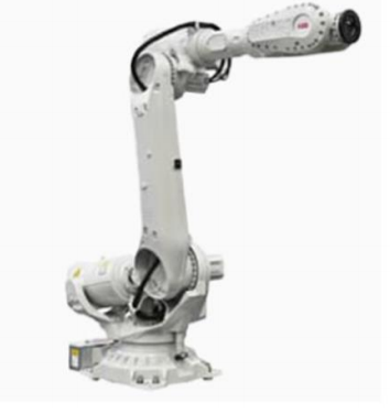
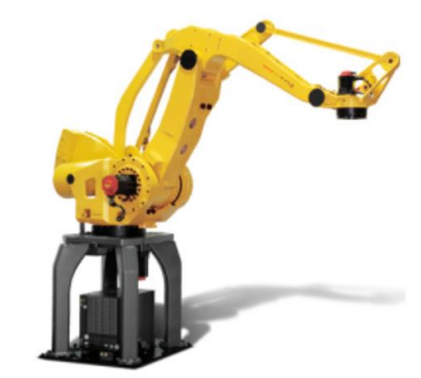
Figure 1-1 ABB IRB6700 robot Figure 1-2 ABB Robot M-410iB700
The world's leading robot manufacturers are revolutionizing vision guidance technology. For example, FANUC utilizes multi-angle cameras and advanced algorithms to improve positioning accuracy during robot gripping, KUKA's monocular vision system pinpoints workpieces and optimizes edge recognition, ABB has developed an efficient glass handling system with image sensors and adsorptive end-effector, and SYSTEMATIX has introduced a compact vision-guided response system that combines distance sensors and search functions to provide an optimized solution for six-axis robots that significantly reduces production cycles and improves accuracy.
In China, major research institutions and enterprises are actively developing intelligent robot systems based on machine vision. For example, Chongqing University and Hangzhou Haikang Robotics Co., Ltd. have launched specialized automatic robot assembly systems and multifunctional robot motion control platform software, respectively, while Zhejiang University has applied machine vision technology to the assembly process of automotive air-conditioning compressors.
The development and application of these technologies have not only improved the operation efficiency and accuracy of robots, but also revolutionized industrial automation and intelligent manufacturing, which are expected to be applied and promoted in a wider range of industrial fields [5].
Although depalletizing robots play an important role in industrial production, they still face some application challenges. First, the flexibility and adaptability of depalletizing robots in handling irregular or shaped items still needs to be improved. Traditional depalletizing systems often rely on preset programs and fixed operating procedures, which perform well when handling standardized items, but their performance is often greatly reduced for items with different shapes, sizes and weights. Therefore, how to make robots more intelligent to adapt to changing working environments has become an urgent problem.
Second, many intelligent depalletizing systems are usually designed for specific environments and needs and lack versatility. This not only limits their application scope, but is often accompanied by higher costs and complex operation processes due to customization requirements. In addition, these systems are less adaptable to the surrounding environment and cannot flexibly respond to changing production environments.
In addition, although machine vision technology has made significant progress in depalletizing robots, especially in vision guidance, there are still deficiencies in some aspects of the system. For example, there is still room for improvement in the relevant pre-processing of the acquired images and 3D localization accuracy. These technical limitations affect the overall performance of the machine vision system, and more in-depth research and improvement are urgently needed.
In terms of automatic unpacking products, the current application is mainly focused on the removal of FMCG jacket film. This type of equipment is mainly produced by German and South Korean manufacturers, but their cost-effectiveness is low. A major problem faced by these automatic unpacking equipment is the difficulty of customizing and flexibilizing the operation according to the specifications of different gauges and packaging types. This limitation not only reduces their potential for application in various production lines, but also increases the challenge of adaptation in changing production demands.
1.3. Purpose and significance of the study
The study of intelligent unpacking process and the development of intelligent unpacking devices will help to improve the efficiency of the new warehousing of measuring instruments and make the deployment of digitalization, intelligence and automation in the pre-warehouse area more complete. At the same time, it also helps the secondary recycling of package materials, making the whole operation process more environmentally friendly and efficient.
2. Key Technologies and Difficulties
For the specific unpacking operation scene, the difficulty of automatic unpacking technology of measuring instruments is mainly reflected in the vision technology, automation control technology, mechanical automation technology and other disciplines of the cross-application of technology.
2.1. Complex outer packaging structure
The outer package of the new electric energy measuring instruments has 4 packing tapes, and there is winding film from the top to the surroundings, and inside the winding film there is an L-type blocking strip, and the L-type blocking strips are distributed on the top four edges and the surrounding right-angled edges, which is a complicated structure of the outer package, and leads to great difficulty in realizing automatic unpacking.
2.2. There are certain irregularities in packaging
At present, the new outsourcing of power measuring instruments are basically manually packaged, packaging irregularities, packaging differences between different manufacturers is even greater, and the position of the packing tape is not uniform or even packaged in the winding film inside the situation, the winding film winding direction is not the same or even a splicing of the situation, L-type retaining strips placed in a different position or even the length of the difference in the case of the irregularities of these packages, leading to the realization of the automated unpacking difficulty is very large.
3. Content of the study
The object of the study is the new electric energy metering instruments in wooden pallets supplied by the supplier. Research content: the use of flexible, automated custom unpacking equipment for intelligent unpacking of new pallets.
Supplier supply of new electric energy metering equipment, each tray full of tow storage 32 boxes, 4 boxes per layer, a total of 8 layers, using wooden pallets, pallets outside the packing tape, wrapping film, wrapping film inside the L-type blocking strips. As shown in Figure 3.
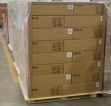
Figure 3. New Product Availability
4. Design options
4.1. Automated unpacking process for electrical energy meters
4.1.1. Unloading of new products: suppliers according to the supply plan will be the new supply of electric energy measuring instruments to the automated unloading equipment will be new from the car to complete the unloading operation.
4.1.2. New temporary storage: after the unloading is completed, the first pallet as a unit of temporary storage, to be sampling is completed, after data entry, the intelligent transfer equipment will transfer the pallet of goods to the unpacking robot caching station, ready to unpacking operations;
4.1.3. Appearance Inspection: The pallet is rotated 360° on the turntable of the automatic unpacking robot workstation for code scanning and appearance inspection to determine whether it is the corresponding pallet number issued by the system work order, if so, it will be ready for unpacking operation.
4.1.4. Removal of the wrapping film: The unwrapping jig of the unwrapping robot firstly cuts the wrapping film and rolls it into the collection drum by the rotating shaft;
4.1.5. Dismantle the L-type retaining strip: In order to avoid the fall of the retaining strip, it is recommended to apply glue on the outside of the L-type retaining strip to fix it with the inner circle of the winding film when the supplier packs it, and compress and rotate the retaining strip together with the rotating shaft of the unpacking machine for the collection of the winding film to collect it into the barrel.
4.1.6. Packaging material collection: when the collection drum roll diameter reaches 1.0m, the system notifies the automatic transfer equipment to transplant the package material recovery drum to the workstation station, the equipment automatically draws off the drum core, and places the package material in the recovery frame on the pallet.
4.1.7. Bale compression and baling: the recycling frame is transferred to the compression and baling workstation for centralized compression and baling, which is convenient for environmental protection and recycling.
4.2. Intelligent unpacking robot man-made R&D program
4.2.1. Subsystem components
In order to complete the intelligent unpacking operation, the automated unpacking robot robot needs to have the following structure: the main frame, robotic arm, clamping tool, vision subsystem, flexible cutting device, power rewind arm, turntable and so on.
4.2.2. Design justification premise
After analyzing and justifying the shape and package of a large number of new palletized goods of measuring instruments on site, we recommend:
(1) Packing order: When packing, th1e strapping tape should be bundled first, and then covered with winding film;
(2) Specification requirements: the material and number of wrapping layers need to be consistent, and the end closure should be relatively flush;
(3) Additional adhesive coating on L-shaped stopper: Apply adhesive on the outside of the package to make it fit tightly with the winding film, so that it can be put into the drum together when rotating and recycling, and won't fall off by itself.
4.2.3. Automated design solutions
(1) Main framework
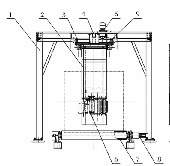
This specialized machine equipment is reverse-designed on the basis of double-arm stretch film winding machine. The frame-type structure has a gantry-type slewing arm mounted on a steel frame with a length and width of about 4m×4m and a height of about 3m. The slewing arm is mounted on the steel frame by means of an internal gear type slewing bearing, and a slewing arm drive motor is mounted on the steel frame. The arm is equipped with a film winding device, which is designed to wind up the film and the L-shaped stopper during the rotation of the arm driven by the motor. The roll diameter is automatically measured by the optical encoder, and the winding device is automatically adjusted to the height of the center of the mechanism by the lifting motor according to the size of the roll diameter, while the motor is directly connected to the reducer to drive the rubber rollers to work with the winding device. As shown in Figure 4-1.
| 1- Frame structure; 2- Slewing arm; 3- Slewing bearing shaft; 4- 3D vision sensor and measuring encoder; 5- Slewing arm drive motor; 6- Film rewinding device; 7- Rubber rollers; 8- Rubber roller drive motor; 9- Release device to lift the active sprocket |
Figure 4-1 Main view of the main frame structure of the unpacking machine and robot | |
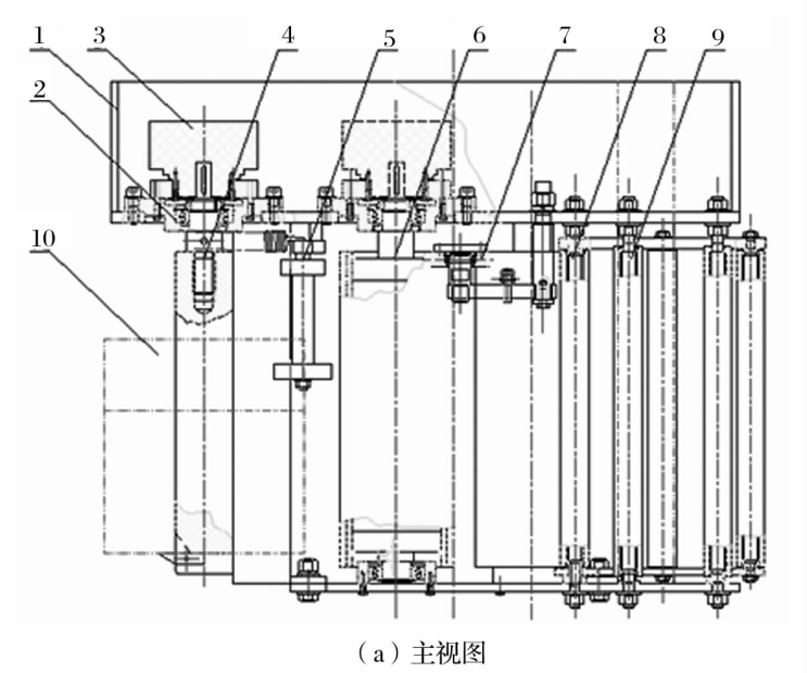
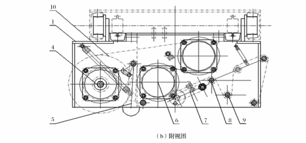
(2) Film rewinding device
The film rewinding device relies on the tension of the packaged article to stretch the film and wrap it around the article, while the tension of the film itself can be adjusted by the size of the braking torque, which is widely used in the packaging industry. The film rewinding device is shown in Figure 4-2, and its structure mainly consists of rewinding device structure frame, bearing group, electromagnetic powder brake, material roll shaft group, S roll, movable guide roll, fixed guide roll, material roll detection device, S roll pressure device and other components.
| 1- The structural frame of the rewinding 2- Bearing set; 3- Electromagnetic powder brake; 4- Material reel set; 5- Material roll detection device; 6- S roll; 7- S roll compression device; 8- Movable guide roller; 9- Fixed guide rollers; 10-Package recycling rolls |
(a) front view | |
| |
(b) top view | |
Figure 4-2 Schematic diagram of film rewinding device | |
(3) Automatic film cutting and clamping mechanism
This mechanism is used for automatic film cutting and clamping operation of the unwrapping robot, including an action triggering mechanism, an upper film cutting mechanism, an auxiliary winding mechanism and an electrical control system. The action triggering mechanism is mounted on the underframe of the winding film rewinding mechanism, and includes a blocking frame, a blocking arm assembly, a blocking cushion, and a blocking strength adjusting assembly, etc., wherein the blocking strength adjusting assembly is provided with an adjusting screw, and a reset spring is mounted on the screw; and the blocking arm assembly includes a fixed axle, a blocking stopper arm, and a blocking wheel and other parts;
Film Cutting Mechanism
Fixed on the rotating disk of the base of the unpacking equipment, including the film cutting power transmission mechanism, film clamping mechanism, power mechanism, orientation mechanism, etc.; as shown in Figure 4-3
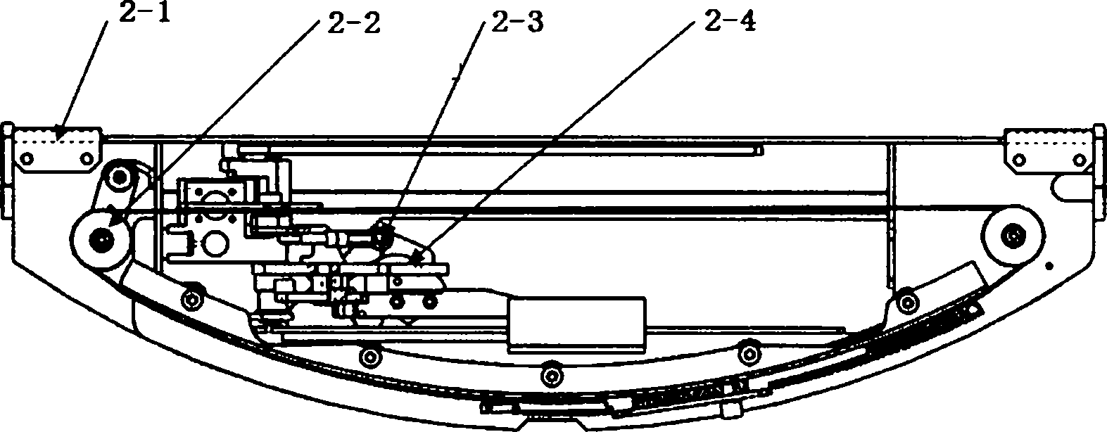
Figure 4-3 Schematic design of film cutting mechanism
2-1 Film Cutting Frame Mechanism
2-2 Power transmission mechanism
2-3 Clip membrane structure
2-4 Film Breaking Mechanism
The frame mechanism is fixed on the rotating disk of the unpacking machine, and during the rotation process, it is converted into linear slider movement by the input collision wheel of the power transmission mechanism to drive the film clamping mechanism and film cutting mechanism to carry out linear movement continuously, and realize a series of coherent actions such as film cutting and film clamping through the guiding edge and guiding groove in the frame mechanism during the linear movement of the film clamping and film cutting mechanism and the film cutting mechanism.
Film clamping mechanism
It includes film clamping head, film clamping pull spring, film clamping pull rod, trigger arm reset, film clamping trigger wheel, driving slider mechanism, etc., as shown in Figure 4-4;
| 2-3-1 Film Clamp Head 2-3-2 Clamped membrane tension spring 2-3-3 Clip film action lever 2-3-4 Trigger arm reset spring 2-3-5 Clip film trigger wheel 2-1-7 Drive Slide Mechanism |
Figure 4-4 Refined design of film clamping mechanism | |
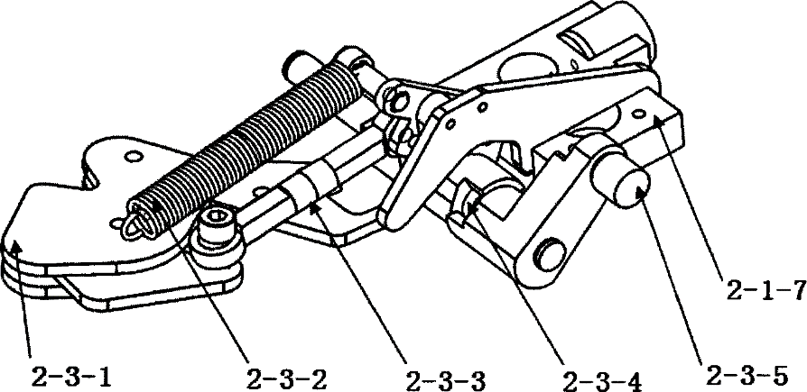
In the process of driving the slider mechanism to translate, the driving slider mechanism gradually rises from the mechanism hidden cavity, while the film clamping trigger wheel changes along the edge of the film clamping action guide plate. At the same time in the film tension spring will be stretched at the same time, pulling the film action lever will be clamped head open, in order to realize the release of the clamped head; near the far end of the stroke when the clamped film trigger wheel gradually reset, at this time in the clamped film under the action of the spring clamped head reset; in the device back to the return journey to maintain the state of the clamped head unchanged to return to the mechanism hidden in order to complete a cycle of work.
4.2.4. Visual localization algorithms
(1) Match the problem description:
In the intelligent unpacking robot workstation, 3D sensors are fixed at specific locations and the point cloud matching technique is used to obtain the positional information of the pallet, which effectively improves the accuracy and efficiency of the automated operation. The 3D point cloud matching problem is described as follows:
Given a set of n-dimensional point sets M representing the model and a set of n-dimensional point sets D representing the measurement data, solve the similarity transformations between the 2 point sets, including the rotation transformation R and the displacement transformation t, such that the weighted squared error E between the measurement data and the model after the transformation is minimized.
\( M=\begin{cases}{m_{i}}\end{cases}|{m_{i}}∈{R^{n}},i=1,...,{N_{m}}\rbrace \) (1)
Where N is the number of n-dimensional point sets
\( D=\begin{cases}{d_{j}}\end{cases}|{d_{j}}∈{R^{n}},j=1,...,{N_{d}}\rbrace \) (2)
\( E(R,t)=\sum _{i=1}^{{N_{m}}}\sum _{j=1}^{{N_{d}}}{w_{ij}}||{m_{i}}-(R{d_{j}}+t)|{|^{2}} \) (3)
where, wi j describes the matching relationship between model point mi and measurement point dj. When the two are matching points wi j = 1; otherwise wi j = 0.
In real-world applications, the robotic system needs to first acquire a set of model point sets M, which contains information about the initial position of the pallet relative to the robotic arm in a particular state. This step is crucial as it provides a reference point for subsequent operations and ensures that the robotic arm is able to accurately position and handle the items on the pallet. To perform this process, the 3D depth sensor continuously captures a set of measurement points in a real-time environment, i.e., the current point cloud data of the pallet. This data is processed through an advanced point cloud matching algorithm to generate a real-time motion estimate of the pallet. This estimation relies on accurate measurement of the pallet position and fine control of the robotic arm motion to maintain consistency in the relative position and orientation of the two. As the work process unfolds, the robotic system continuously updates and corrects the relative positional information between the pallet and the unpacking equipment. This dynamic updating mechanism ensures the efficiency and accuracy of the unpacking process, especially when dealing with high-volume, fast-paced industrial operations. By constantly comparing the modeled point set M with the set of measured points acquired in real time, the system is able to precisely track and adjust the position of the pallet, ensuring that the robotic arm can accurately perform its unpacking tasks. This position tracking method, based on 3D depth sensors and point cloud matching technology, not only improves the operational efficiency of the unpacking robot, but also greatly enhances its ability to adapt to different working environments. In addition, the application of this technology reduces the need for environmental modifications and lowers the overall cost, while increasing the flexibility and scalability of the system. Therefore, this approach is particularly important in the field of modern industrial automation and brings new possibilities for the development of automation technology.
(2) Matching problem solving
In point cloud matching for visual localization algorithms, the key lies in the initial estimation of the similarity transformation parameters and precise localization through iterative optimization. Accurate initial estimation is crucial to avoid falling into local minima. Researchers develop highly discriminative feature descriptors for this purpose to improve the global search matching efficiency. The matching process includes: extracting the feature points of the model point set M and the measurement point set D to compute the descriptors; estimating the matching points based on these features to derive the similarity transformation relationship; excluding the mis-matches through repeated sampling and validation; and, finally, the optimized data is used for exact matching. In addition to traditional 2D feature descriptors such as SIFT and FAST, there are also descriptors designed specifically for point clouds, such as PFH and FPFH.These feature descriptors provide a more diversified and efficient solution to the point cloud matching problem. [6].
The PFH is based on the normal relationship between the center point and its k-neighbors. The PFH calculates the deviation of the normal between each of the k neighboring points, which are connected to each other inside a sphere of radius r at the center point, and establishes a local coordinate system uvw at one of the points, which is described as follows:
u = ns (4)
v = \( u×\frac{{p_{t}}-{p_{s}}}{||{p_{t}}-{p_{s}}||} \) (5)
w = u \( × \) v (6)
where ns is the normal vector of the center point ps; pt is the coordinates of the neighboring point. the deviation of the normals of the two points of the uvw coordinate system can be described by 3 angles:
α= v \( × \) nt (7)
= \( u×\frac{{p_{t}}-{p_{s}}}{d} \) (8)
= atan (w . nt , u . nt ) (9)
In 3D point cloud processing, the point feature histogram (PFH) and its accelerated version, the fast point feature histogram (FPFH), are the key characterization algorithms.The PFH describes the point pairs within each domain as a quaternionic feature by combining the three plumbline declinations α, φ, and θ as well as the distances between the pairs of points d. The PFH is a quadratic characterization algorithm which is used to characterize the point pairs within each domain by combining their spatial position information with their angular relationships. This approach not only contains the spatial location information of the points, but also integrates the angular relationship between them, enabling the descriptor to more comprehensively express the features of the point cloud data. In practice, the PFH feature description divides the feature space into multiple subintervals, and the final PFH description is constructed by counting the distribution of points within each subinterval. This method effectively captures the structural information of the point cloud by quantifying its local features.
In order to reduce the computational burden of the point feature histogram (PFH) descriptor in 3D point cloud processing, the fast point feature histogram (FPFH) algorithm has been creatively proposed.The core innovation of the FPFH algorithm is that, instead of focusing on the complex relationships between all pairs of points within the point cloud domain, it concentrates on the relationships between the central point and its neighboring points. The application of this strategy significantly reduces the amount of computation. Specifically, the FPFH algorithm computes only the vertical features between the center point and its surrounding points, greatly simplifying the entire processing. Further, the algorithm further optimizes the computational efficiency by performing a weighted average of the feature histograms computed for each neighboring point. This simplified process not only significantly reduces the computational cost of the algorithm, but also ensures the accuracy of the final result, which is similar to the performance of the original PFH descriptor.The greatest advantage of the PFH algorithm is that it effectively reduces the computational burden while accurately capturing the local features of the point cloud data. This balance of computational efficiency and accuracy makes FPFH an efficient and reliable tool in the field of 3D point cloud processing, which greatly advances the development of 3D point cloud data analysis and processing techniques. With this innovative approach, the FPFH algorithm provides a faster and more efficient solution for point cloud feature extraction and subsequent application operations, such as object recognition and classification.
PFH and FPFH algorithms face challenges when dealing with sparse point clouds or low curvature surfaces. For this reason, PPF algorithms have been developed to describe the global surface curvature variation and effectively improve the matching of weak textures and simple surface regions. In addition, combining image information, such as utilizing the Chamfer matching method and Haussdorf distance method, which relies on image edge information, also provides solutions, albeit subject to illumination and background variations.
In contrast, the Linemod algorithm [7] considers both 3D object surface normal vectors and 2D image gradient information. This method performs better in point cloud matching because it not only focuses on the spatial distribution of the point cloud, but also incorporates the texture information of the image, thus providing more accurate and stable matching results in complex scenes. In summary, each of these methods has its own characteristics and application scope, and they jointly promote the development of point cloud processing and matching technology.
In this study, the advantages of PPF (Pairwise Geometric Histogram) algorithm and Linemod algorithm are combined to propose an innovative point cloud matching method. This method combines the local texture features of the image and the global curvature change information of the 3D point cloud to improve the matching accuracy and efficiency. Meanwhile, in order to capture the image information more comprehensively, this method extends the traditional PPF descriptor from 4 to 7 dimensions and introduces RGB color information, which enhances the expressiveness of the descriptor and the matching effect, described as follows:
\( {PPF_{color}}=(∥d∥, {a_{1}}, {a_{2}}, {a_{3}},{_∂}R, {_∂}G, {_∂}B \) )(10)
d = p2-p1 (11)
\( {a_{1}}= ∠ ({n_{1}} , d ) \) (12)
\( {a_{2}}= ∠ ({n_{2}}, d ) \) (13)
\( {α_{3}}= ∠ ({n_{1}} , {n_{2}} ) \) (14)
where p1, p2 are the coordinates of any two points on the surface of the object, n1, n2 are the normal vectors at the two points, and the symbol ∠ stands for the angle between the vectors.
(3) Algorithmic testing
In this study, we developed algorithms based on two well-known open source libraries: the OpenCV and the PCL (Point Cloud Library). Our test environment was configured with 16 GB of RAM and a powerful i7 processor to ensure smooth running of the experiments. The first step of the experiment was to use the Astra Standard Edition Depth Camera, a handheld device that connects via a laptop in order to capture data from different views of the pallet. One set of data was carefully selected as a baseline point cloud and transformed into a matching template, while another set of data simulated the trajectory of a forklift truck on the job. The next key step was to apply a point cloud matching algorithm that we designed with the aim of accurately estimating the difference in position between these two sets of data. Through this matching process, we were able to capture and analyze the change in the pallet's positional attitude as the forklift moved. The final stage of the experiment involves overlaying and mapping these two sets of point clouds into the same coordinate system based on the estimated positional changes for detailed comparison and analysis. This series of experimental steps aims to demonstrate the practicality and efficiency of our algorithm. Through actual data collection, processing and analysis, we not only demonstrate the power of the algorithm in handling complex point cloud data, but also verify its effectiveness in real-world application scenarios. The experimental results show that the algorithm is able to accurately capture and analyze the positional changes of objects in dynamic environments, which is of great significance in improving the efficiency and accuracy of industrial automation and logistics systems.
In order to increase the speed of operation and improve the matching effect, this paper adds preprocessing before the recognition algorithm, as shown in Figure 4-5
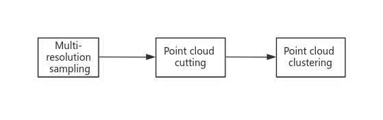
Figure 4-5 Point Cloud Preprocessing Flow
In order to enhance the efficiency of the ICP algorithm, several optimization measures are adopted in this study. First, the number of iterations and running time of the ICP algorithm are effectively reduced and the influence of the initial value is mitigated by a multi-resolution downsampling method that starts from a low-resolution point cloud and gradually increases the resolution. Second, the known camera inclination and pallet distance information are utilized by cropping the point cloud data in order to narrow down the search range and reduce the amount of data. Meanwhile, Euclidean Cluster clustering segmentation is performed on the point cloud to select the cluster with the smallest depth direction as the target point cloud to improve the matching accuracy. These strategies substantially improve the efficiency and accuracy of the point cloud matching process, especially in the experimentally set pan, rotate, and scale transformation scenarios, as well as in the test range of 2.5 meters directly in front of the pallet and ±30° of horizontal declination of the pallet images acquired as shown in Figure 4-6.
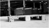

(a) Pallet image (b) Pallet point cloud map
Figure 4-6 Pallet Image and Point Cloud Map
In the experimental results shown in Figures 4-7, the differences and similarities between the two sets of point clouds are clearly demonstrated. The black point cloud on the right side of the figure is our recorded reference pallet data, while the black point cloud on the left side demonstrates the point cloud of the pallet captured during the motion of the simulated forklift. In addition, the gray and white point clouds in the figure represent the positional transformations derived from the point cloud matching algorithm, which are mapped to the observed coordinate system of the forklift. Looking at the black and gray-white point clouds on the left side of the figure, it is clear that the two overlap almost perfectly. This phenomenon clearly demonstrates the high accuracy achieved by our point cloud matching algorithm in calculating the forklift position. This not only shows the theoretical validity of the algorithm, but also demonstrates its reliability and accuracy in practical applications. In addition, this accurate bit-posture matching is essential for understanding the spatial relationships of objects in complex dynamic environments, and it has significant application value in industrial automation and precision robotics operations. This accurate position estimation capability enables the algorithm not only to accurately determine the position changes of the measured point cloud, but also to provide effective guidance data for the forklift control module, thus optimizing the entire control process. This experimental result not only demonstrates the efficiency of the algorithm, but also proves its feasibility and accuracy in practical applications.
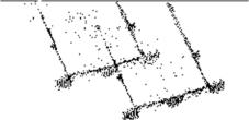
(a) Case 1
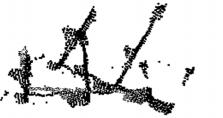
(b) Case 2
Figure 4-7 Pallet Point Cloud Matching Results
4.2.5. Prototype design
Intelligent unpacking robot robot equipment truss body, conveyor device, film cutting device, shearing device, clamping device, sensor components. Software part: vision software, positioning software, control software architecture.
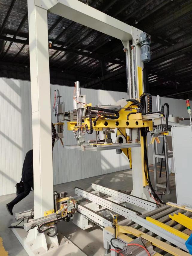
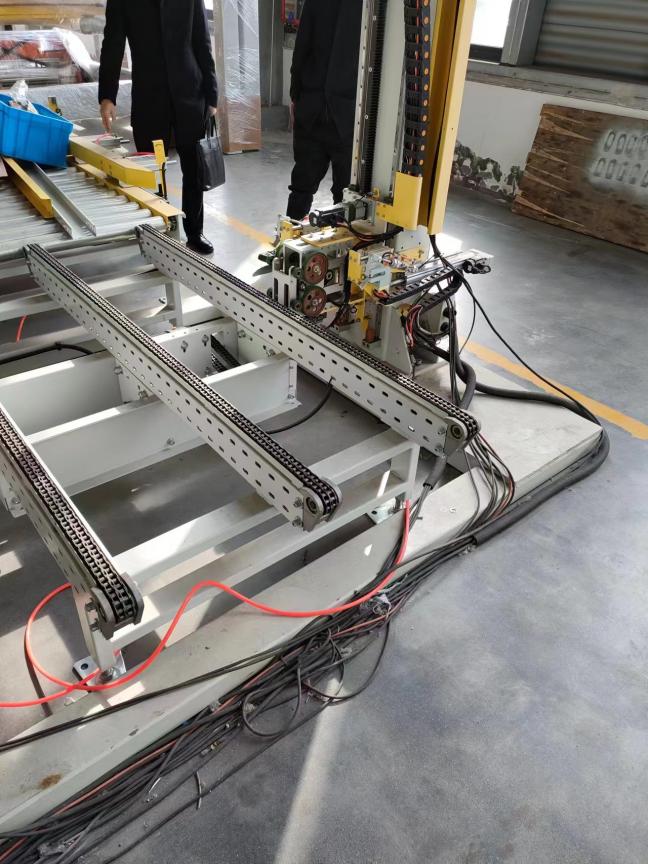
Truss Unpacking Sampler V1.0 (Fixture) Truss Unpacking Sampler V1.0 (Conveyor Chain)
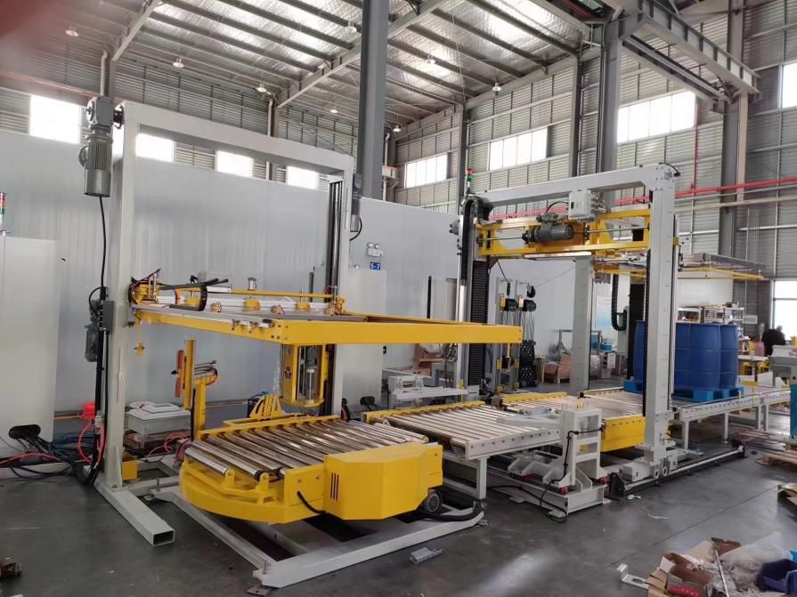
Truss type unpacking prototype machine V1.0 (including caching and unpacking)
5. Comparison of application effectiveness
The use of intelligent unpacking robot workstation, can significantly improve the current manual unpacking work efficiency, relative to manual, improve the efficiency of more than 5 times, , less than or equal to 180 seconds / bracket, at the same time, can reduce labor injuries, the realization of the library of the front area of the work process of automation, digitalization, intelligence.
6. Conclusion
Intelligent unpacking robot workstation for new trays of electric energy measuring instruments, using 3D vision and flexible mechanisms for automatic removal of the outer packaging package, will be able to fill the gaps in the domestic intelligent unpacking equipment, and play a significant role in improving the efficiency of the operation of new measuring instruments.
References
[1]. Wang Guohu. Research and development of key technology of intelligent depalletizing robot [D]. Henan University of Science and Technology,2015.
[2]. HAN Fengtao. Overview of industrial robotics research and development[J]. Robotics technology and application,2021(05):23-26.
[3]. Chen W.-Q. Research status and development trend of industrial robots[J].,2020(24):118-120.DOI:10.16621/j.cnki.issn1001-0599.2020.12D.68.
[4]. Sun Yang. Research on key technology of robotic carton depalletizing based on machine vision[D].ShangdongUnivercityTechnology,2021.DOI:10.27276/d.cnki.gsdgc.2021.000484.
[5]. YANG Wen, SHI Yingchun, LEI Daozhong. Joint stiffness analysis and identification of multi-joint tandem industrial robots[J]. China Informatization,2021(02):82-85+73.
[6]. Zhang X. Application of Fanuc Robotics iRvision vision system in painting production line[J]. Modern Coating and Painting,2019,22(01):68-70.
[7]. Pires J N. Handling production changes online: example using a robotic palletizing system for the automotive glass industry[J]. Assembly Automation, 2004.
Cite this article
Xu,Y.;Lv,M.;Lu,R.;Liu,G.;Ma,Y.;Shi,B.;Li,Y. (2024). Research report on automatic unpacking operation of measuring instrument storage buffer area. Applied and Computational Engineering,50,272-285.
Data availability
The datasets used and/or analyzed during the current study will be available from the authors upon reasonable request.
Disclaimer/Publisher's Note
The statements, opinions and data contained in all publications are solely those of the individual author(s) and contributor(s) and not of EWA Publishing and/or the editor(s). EWA Publishing and/or the editor(s) disclaim responsibility for any injury to people or property resulting from any ideas, methods, instructions or products referred to in the content.
About volume
Volume title: Proceedings of the 4th International Conference on Signal Processing and Machine Learning
© 2024 by the author(s). Licensee EWA Publishing, Oxford, UK. This article is an open access article distributed under the terms and
conditions of the Creative Commons Attribution (CC BY) license. Authors who
publish this series agree to the following terms:
1. Authors retain copyright and grant the series right of first publication with the work simultaneously licensed under a Creative Commons
Attribution License that allows others to share the work with an acknowledgment of the work's authorship and initial publication in this
series.
2. Authors are able to enter into separate, additional contractual arrangements for the non-exclusive distribution of the series's published
version of the work (e.g., post it to an institutional repository or publish it in a book), with an acknowledgment of its initial
publication in this series.
3. Authors are permitted and encouraged to post their work online (e.g., in institutional repositories or on their website) prior to and
during the submission process, as it can lead to productive exchanges, as well as earlier and greater citation of published work (See
Open access policy for details).
References
[1]. Wang Guohu. Research and development of key technology of intelligent depalletizing robot [D]. Henan University of Science and Technology,2015.
[2]. HAN Fengtao. Overview of industrial robotics research and development[J]. Robotics technology and application,2021(05):23-26.
[3]. Chen W.-Q. Research status and development trend of industrial robots[J].,2020(24):118-120.DOI:10.16621/j.cnki.issn1001-0599.2020.12D.68.
[4]. Sun Yang. Research on key technology of robotic carton depalletizing based on machine vision[D].ShangdongUnivercityTechnology,2021.DOI:10.27276/d.cnki.gsdgc.2021.000484.
[5]. YANG Wen, SHI Yingchun, LEI Daozhong. Joint stiffness analysis and identification of multi-joint tandem industrial robots[J]. China Informatization,2021(02):82-85+73.
[6]. Zhang X. Application of Fanuc Robotics iRvision vision system in painting production line[J]. Modern Coating and Painting,2019,22(01):68-70.
[7]. Pires J N. Handling production changes online: example using a robotic palletizing system for the automotive glass industry[J]. Assembly Automation, 2004.