


1. Introduction
In recent years, the research and development of terahertz technology has been in full swing, making it a hotspot for civil and military research in many countries. Due to its unique physical characteristics, it has many distinctive advantages. For example, the penetration of terahertz waves in human tissues can reach several hundred micrometers, so terahertz medical imaging can be used for surface diagnostics, such as skin cancer, oral cancer, breast cancer detection and dental imaging. Not only that, but terahertz spectroscopy is a very powerful technique for characterizing materials and understanding their characteristics in that band. Terahertz spectroscopy has enhanced the understanding of the absorption characteristics of many organic molecules in single crystal, microcrystal and powder samples. This shows that terahertz technology has a promising future in cross-cutting areas such as biology, medicine, communications, and military security. However, terahertz systems still have problems at the specific application level such as device size, operational complexity, low-temperature environment dependence, and cost that severely limit their applications. Therefore, through this review, the physical characteristics of the technology and its corresponding advantages and disadvantages in applications are synthesized, so that we can have a clearer and more comprehensive knowledge of the technology, so that the terahertz technology can have a more far-reaching development in the future.
2. Introduction to Terahertz Waves
In order to have a deeper and more comprehensive understanding of terahertz wave technology, it is necessary to know the physical properties of terahertz waves and their development process. The following article will briefly describe the characteristics of terahertz waves and the advantages of their corresponding properties for industrial applications, as well as their development and current status.
The terahertz band of the electromagnetic spectrum is shown in Figure 1.
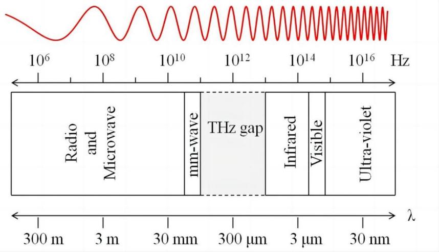
Figure 1. Position of the terahertz band in the electromagnetic spectrum
Terahertz band radiation is characterized by the following:
The quantum energy and blackbody temperature are very low, as shown in Table 1. The low blackbody temperature of RF signals means that their blackbody radiation noise is low, so that the noise interference in the system is small, thus reducing the signal system noise power, improving the purity and reliability of the signal, and reducing the power consumption of the transmitting source. In the modulation and demodulation of the signal, the low blackbody temperature can improve the performance of the system Make THz wave has a great advantage in communication and imaging.
Table 1. Quantum energy of terahertz waves and blackbody temperature
frequency/THz | wavelength/mm | wave number/cm-1 | energy/mev | Blackbody temp/K |
0.03 | 10.000 | 1 | 0.12 | 1.4 |
0.30 | 1.000 | 10 | 1.20 | 1.0 |
1.00 | 0.300 | 35 | 4.10 | 4.0 |
3.00 | 0.100 | 100 | 1.20 | 240.0 |
6.00 | 0.050 | 200 | 2.50 | 290.0 |
20.00 | 0.015 | 670 | 33.00 | 960.0 |
The vibration and rotation frequencies of many biological macromolecules are in the THz band, so a wealth of information about organisms and their materials can be obtained using THz waves. Not only that, the photon energy of terahertz radiation is low, the source power is small, and the penetration depth is less than the thickness of human skin, so it is considered to be safe for the human body.
Terahertz radiation has longer wavelengths than infrared wavelengths; therefore, compared to infrared waves (in the micrometer range), terahertz waves scatter less and penetrate deeper (in the centimeter range), where dry and non-metallic materials are transparent but opaque in the visible spectrum.
Terahertz waves have a wide instantaneous bandwidth (0.1 to 10 THz), which facilitates high-speed communications, as shown in Figure 2. Terahertz sources usually contain only a few cycles of electromagnetic oscillations, and a single pulse band can cover from GHz to tens of THz, making it easy to analyze matter over a wide range.
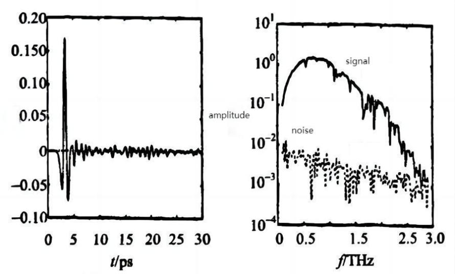
Figure 2. Spectrogram of THz pulse
Terahertz technology in the history of development should be traced back to infrared and microwave. The development of these two disciplines began in the early 1980s (i.e., before the 1970s), when the terahertz band on both sides of infrared and microwave technology was relatively mature, but people still have a very limited understanding of the “transition zone” between the two (so the early terahertz band also has a Terahertz gap (THz gap) called), and only in electronics and photonics scholars of microwave and infrared at both ends of a more in-depth exploration of the concept of today’s terahertz and a wealth of applications based on terahertz wave technology. It also shows the transition from macroscopic classical theory to microscopic quantum theory and the process of electron optics and photon optics.
In recent years, the explosive growth of terahertz-related technologies has continuously driven the performance of key devices such as terahertz sources and sensors. Terahertz time-domain spectroscopy research and then developed sub-millimeter-wave spectroscopy and imaging technology, which is not only applied in the security system on the detection of dangerous chemicals, explosives detection, hidden weapons security checks, etc., but also can be used for environmental monitoring, industrial product testing, materials science surface detection; not only that in medical diagnostics, imaging terahertz technology has also made a lot of progress, such as a new type of cancer pathology detection system [1]. In the field of communications, terahertz waves have many applications, such as terminal link control (TLC) for broadband secure point-to-point communications, and high-definition synthetic aperture radar (RAC).
3. Key devices of terahertz system
Similar to other RF systems, the terahertz system is also based on the source, filter, and sensor, which are the three key devices [2]. The terahertz source is the core of the terahertz system and the source of terahertz wave generation; common terahertz sources include lasers, electric dipole antennas, and photo detectors, etc. The terahertz filter is used to selectively transmit or block electromagnetic waves in a specific frequency range in the terahertz band. And the role of terahertz filters is to selectively transmit or block electromagnetic waves in a specific frequency range of the terahertz band. It can regulate and control the propagation and transmission of terahertz radiation on the nanoscale, which has important scientific and technological applications. Finally, terahertz detectors (sensors) are devices that detect and measure terahertz radiation.
In recent years, significant progress has been made in the reliability and room temperature of terahertz sources and sensors, thus providing bright prerequisites for the practical application of terahertz technology.
3.1. Terahertz sources
There are three existing terahertz sources based on three principles. Respectively, based on thermal principles such as blackbody (carbon silicon rods) and lamps, its principle is to use the thermal effect to produce terahertz radiation.
Based on the principle of electronics, such as the Gunn diode (Gunn) and the backward wave tube (BWO), based on the principle of electronics, a terahertz source uses the nonlinear effect of electrons to generate terahertz radiation. A common electronics principle utilizes frequency multiplier techniques. By feeding a high-frequency signal into a nonlinear material, such as a nonlinear crystal or a nonlinear medium, a frequency multiplier effect, i.e., a multiplication of the frequency of the input signal, will be produced, depending on the nonlinear effect. By using this frequency multiplier technique, high-frequency signals can be multiplied into signals in the terahertz frequency range, resulting in terahertz radiation.
As well as those based on optical/laser principles, carbon dioxide pumped terahertz gas lasers, Optical Parametric Oscillators (OPOs), interpolated continuous wave photomixing sources, and terahertz pulsing methods; terahertz sources based on optical principles utilize the nonlinear effects of light to produce terahertz radiation. A common optical principle is the use of optical photomixing. By interacting two light waves in a nonlinear material, a mixing effect is produced. Based on the nonlinear effect, a new combination of frequencies will be generated that contains light waves in the terahertz frequency range. Through this photomixing technique, terahertz radiation can be produced.
The key to realizing the practical application of terahertz sources in engineering should satisfy the condition of room temperature adjustability [3]. The figure below shows the relationship between the output power and the frequency for most relevant solid-state terahertz sources [4].
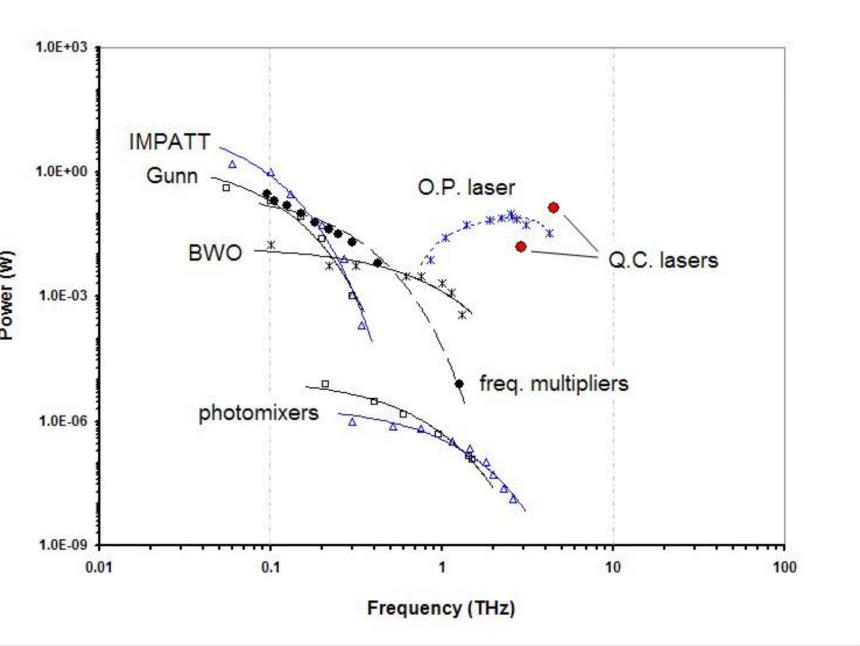
Figure 3. Acquired power output of continuous-wave terahertz and sub-terahertz sources as a function of frequency
Some progress has been made with terahertz sources, with the development of different techniques based on thermal principles, laser excitation and electron acceleration. However, terahertz sources still have some application limitations. First, existing terahertz sources generally face the problems of low output power and low efficiency, which limit their practical applications. Second, the frequency tuning range of terahertz sources is limited, making it difficult to achieve full-band coverage. Again, the large size and complexity of some terahertz sources as well as the high manufacturing cost are also constraints. Difficulties that need to be overcome for the future development of terahertz sources include improving output power and energy conversion efficiency, expanding the frequency tuning range, realizing more compact dimensions and simplified manufacturing processes, and exploring new excitation mechanisms and materials. In addition, the reliability and stability of terahertz sources need to be strengthened to meet the needs in practical applications. Overcoming these difficulties will promote the further development and application of terahertz science and technology.
3.2. Filters
The filter module is mainly used in spectroscopy, as shown in the figure below, and can be used for the study of the atmospheric transmission window in the terahertz band and the spectral lines of strong absorption of terahertz waves by water vapor.
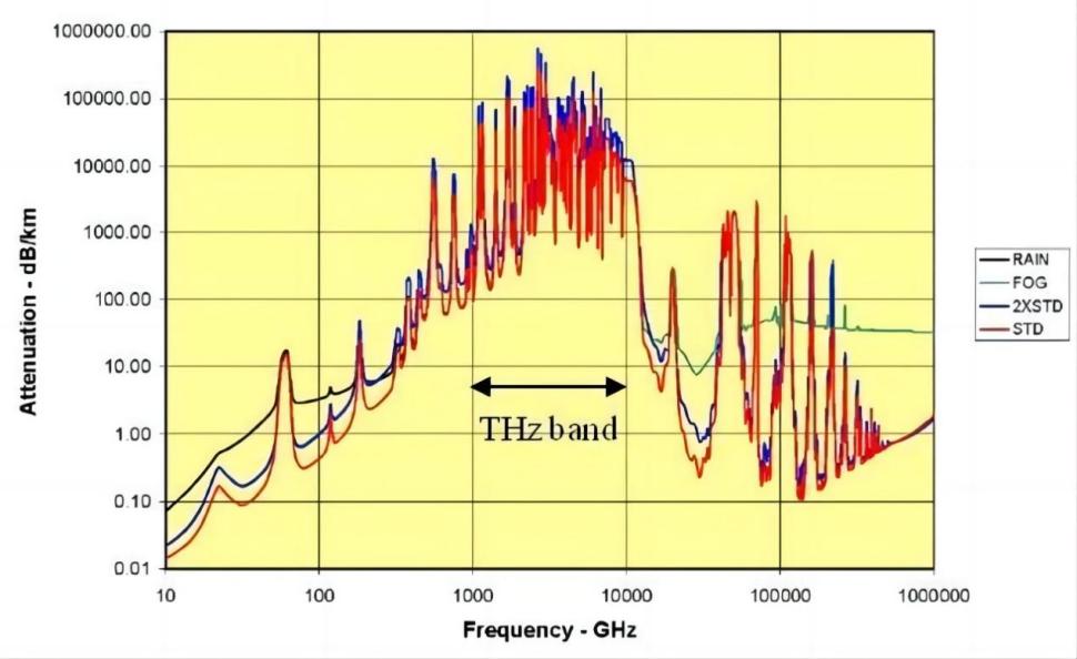
Figure 4. Sea level attenuation under different atmospheric conditions(Rain = 4 mm/h; Fog = 100 m visibility; STD = 7.5 g/m3 water vapour; 2×STD = 15 g/m3 water vapour.) [5]
Commonly used terahertz filter designs include metallic grating structures, terahertz Dual-polarized, and opening parts. These filters enable the selection of a specific frequency range for transmission and blocking, and are used in terahertz communications, imaging, spectroscopy, and other fields. However, the same terahertz filters still have some limitations, and despite the fact that there are a number of design and preparation methods available, the realization of broadband or multi-channel terahertz filters is still facing difficulties. Not only that, the existing terahertz filters still need to be improved in terms of frequency tuning range, transition region width, transmission loss and manufacturing cost.
3.3. Sensors
A terahertz detector (sensor) is a device used to detect and measure terahertz radiation. Terahertz detectors work based on the principle that terahertz waves interact with matter. It is only in recent years that terahertz detectors have become important devices in the application of terahertz technology.
Common types of terahertz detectors with their characteristics are the following. Based on thermoelectric detection of low-temperature radiometric thermometers, which are characterized by temperature-based measurements, insensitive to frequency, working at a temperature of 4K, with good sensitivity, and Golay (Golay) detectors, which are based on temperature measurements, working at room temperature, with higher sensitivity, slower response speed, easy to age and damage, and limited linearity. There are also pyroelectric detectors, which will be converted from a change in dielectric constant into an electric signal Thermal detector, limited sensitivity.
Detection based on the principle of electronics have photoacoustic sensors, which is based on the pressure sensor of the closed gas chamber, can detect terahertz radiation, through the built-in ohmic heating (direct resistance heating) metal film inside the gas chamber to achieve self-calibration, with good sensitivity.
There are also new focal plane microbolometer thermometers developed in recent years, which are more reliable and have acceptable sensitivity. Excellent performance has been obtained with detectors using uncooled microbolometer technology for low-cost, high-pixel arrays. One of these detectors utilizes thin-film vanadium oxide material as a thermally isolated microbridge with a high temperature coefficient of resistance (TCR) to achieve higher reliability and better performance.
The following briefly describes the regular pump detection method based on optoelectronic sampling coherent detection, i.e., the use of optical rectification by the laser pump pulse irradiation of the crystal to produce a detectable terahertz pulse signal. The terahertz wave is co-incident with the laser beam at the same position of the nonlinear detector crystal, and the beam modulation is encoded to produce a polarization change proportional to the terahertz field strength, in order to obtain excellent terahertz bandwidth and sensitivity. [6]
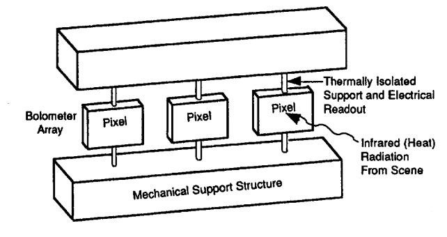
Figure 5. Illustration of bolometer [7]
Terahertz detectors have a wide range of applications in the fields of medicine, material science, and security detection. Similarly, the current performance of terahertz detectors needs to be improved, such as in terms of sensitivity, response time and frequency range. Future developments will focus on the exploitation of new materials, structures and technologies to improve the performance of terahertz detectors and to promote the widespread use of terahertz technology in practical applications.
4. Practical applications of terahertz technology-Thermodynamics-based’THz Torch’ Wireless Communications Links
A short-range secure communication system based on high-frequency terahertz waves in the thermal infrared band from the Centre for Terahertz Science and Engineering at Imperial College London is presented below to demonstrate the specific applications of terahertz waves in modern engineering and technology as well as the various application-oriented design methods used in the paper. The following section describes the basic architecture and design details and gives a demonstration of single-channel operation in the 25-50 THz band.
4.1. Introduction
The ‘Thz torch’ technique is a close-range, low-cost, secure communication technology based on high-frequency terahertz (far-infrared) waves [8]. Unlike most conventional terahertz technologies based on high-cost coherent signal generation and detection, the Terahertz Torch is based on incoherent thermal radiation in the high-frequency band of the terahertz wave spectrum (thermal infrared). Its essence for the realization of ultra-low-cost engineering applications of blackbody radiation spectrum, through the isolation of thermal noise spectrum energy into the preset channel, so that its energy can be independently pulse modulation and transmission. The basic architecture is shown in Figure 7 [9].
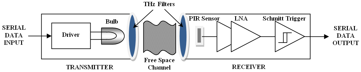
Figure 6. Typical “terahertz torch” channel
4.2. Basic single-channel architecture
4.2.1. Basic component. (1) high-frequency terahertz thermal noise source.
Today, there are a variety of terahertz sources based on electronic or photonic technology, and the blackbody radiation source chosen for this system closely meets the purpose of low-cost applications with its simple structure, ease of adjustment, and simplicity of purchase. The principle is to use thermodynamic methods to directly generate high-frequency terahertz thermal noise. However, in contrast to systems using conventional terahertz sources, because the thermal noise is incoherent, only the output noise power can be measured and no other carrier information such as phase and polarization can be obtained.
In principle, many types of thermal radiation can be used to generate high-frequency terahertz radiation. The system presented in the paper uses a miniature incandescent lamp, a 400 mW Eiko 8666-40984 as shown in Figure 8, to demonstrate the principle. It should be mentioned that the blackbody radiation emitted using this commercial off-the-shelf (COTS) lamp is partially defective in the high-frequency terahertz band due to the low emissivity of the tungsten wick, the poor window transmittance, the absence of an additional collimating lens, and the high scattering loss of the backward reflector.
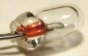
Figure 7. Eiko 8666- 40984 (calibre = 2.6 mm, length = 6.3 mm)
(2) High frequency terahertz radiation sensors.
First, we have to introduce three parameters to characterize the sensor’s performance:
Define the specific detectivity as
\( {D^{*}}=\frac{\sqrt[]{A}}{NEP}=R∙\frac{\sqrt[]{A}}{{S_{n}}}(\frac{{mHz^{\frac{1}{2}}}}{W}) \)
The input noise power as
\( NEP=\frac{{S_{n}}}{R}(\frac{W}{{Hz^{\frac{1}{2}}}}) \)
The response rate is
\( R=\frac{u}{{Φ_{s}}}(\frac{V}{W}) \)
In the formula: A is the area \( ({m^{2}}) \) , Sn is the output noise voltage spectral density \( (\frac{V}{Hz}) \) , u is the output voltage \( (V) \) , \( {Φ_{s}} \) is the input/output radiant flux \( (W) \) .
The system foregoes high-performance, but high-cost photonic detectors that require cooling for noise reduction in the choice of sensors: which its \( {D^{*}} \) is approximately \( {10^{10}}cm∙\frac{{Hz^{\frac{1}{2}}}}{W} \) , its fast response time less than \( 1μs \) ;The author pioneered the use of a Passive Infrared Sensor(PIR), The specific detection rate of thermal sensors is two orders of magnitude lower than that of typical photonic detectors, i.e. \( {10^{8}}cm∙\frac{{Hz^{\frac{1}{2}}}}{W} \) , the response time is 0.25 times lower; however, in the development of this low-cost thermodynamic model, the very wide instantaneous bandwidth and the fact that it is ready for application at room temperature make it a superior engineering solution.
(3) High frequency terahertz filters.
Since thermal radiation has a continuous spectrum, filters are needed to ensure that the channel operates in a preset spectral range. The same long-pass filter was used for the transmitter and receiver in the 25 to 50 Hz range, as shown in Fig. 9, with a spectral transmittance greater than and an average insertion loss of 2 dB.
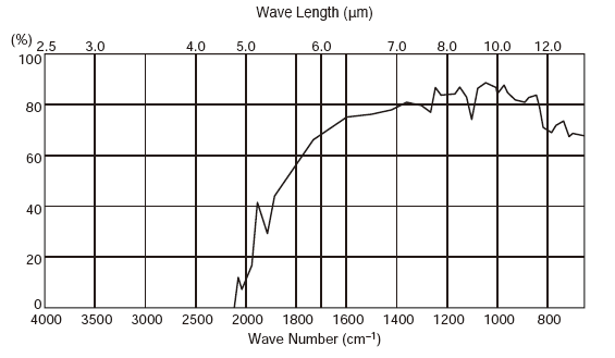
Figure 8. \( 5μ \) m Spectral Emissivity of Long Pass Filters
4.2.2. Basic subsystem design. (1) Transmitter subsystems.
The transmitter in this system consists of five Eiko8666-40984 miniature incandescent lamps, which are packaged together to form a cylinder with an outer diameter of 8.2 mm, as shown in Figure 8.
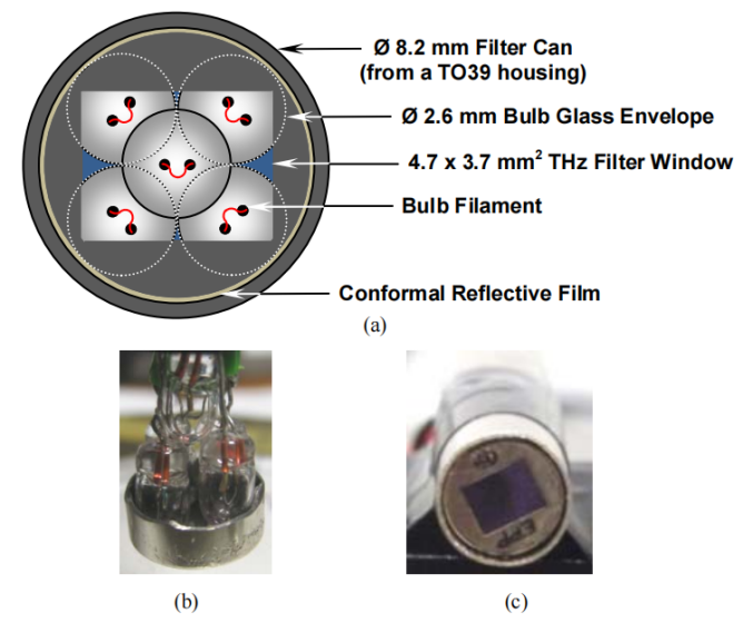
Figure 9. Terahertz transmitter front end (a) back to front view; (b) assembled front end; (c) complete transmitter
A. Measurement of filament operating temperature
The tungsten filament temperature of the bulb is an important parameter in this system and for this reason the authors designed a simple test circuit to determine the individual bulb temperatures as shown in Figure 10.a. The temperature of the tungsten filament of the bulb is the temperature at which the bulb is turned on. The turn-on thermal time constant here is the time required to rise from 10% to 90% of the final steady state temperature. As can be seen in Fig. 10.b, with the rising edge of the input pulse, the voltage output drops from = 0.839 V to 0.652 V and then rises to a steady state value of 0.705 V. This is a relatively slow response time. This relatively slow response is due to the fact that the turn-on thermal time constant of the entire circuit is approximately 32 ms (the electrical time constant in this circuit is many orders of magnitude shorter). The turn-on thermal time constant for a single bulb (i.e., without any additional collector resistor RC) was found to be 155 ms.
(a) 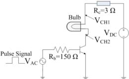 (b)
(b) 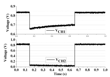
Figure 10. (a) Test circuit (and emitter driver circuit with RC = 3 Ω); (b) Measured voltages VCH1 (upper trace) and VCH2 (lower trace)
The following describes how to determine the filament operating temperature with acceptable accuracy. Using an RLC meter, the series resistance and inductance of a single unbiased bulb at room temperature are measured as and , respectively, with an electrical time constant of only. For a tungsten bulb, the filament resistivity can be expressed by the following quadratic empirical formula from 200K to 3000K as
\( ρ(T)=2.228×{10^{-8}}∙{T^{2}}+2.472×{10^{-4}}∙T-1.859×{10^{-2}}(Ω∙μm) \)
Resistivity at room temperature. The resistance of 5 bulbs connected together at room temperature is measured directly as. Assuming that the counting resistance of the connecting wires is negligible, the resistance of each filament is averaged. Assuming that the tungsten filament is an ideal cylinder with uniform cross-sectional area (CSA) and length (l),its resistance R has the following relationship
\( ρ(T)=R(T)∙{(\frac{CSA}{l})_{eff}}(Ω∙cm) \)
According to the above equation, the effective ratio of its cross-sectional area to its length is obtained: \( {(\frac{CSA}{l})_{eff}}=1.09×{10^{-6}}(cm) \) . Assuming again that it is uncorrelated with temperature, the operating temperature of the bulb can be estimated to an acceptable accuracy by indirectly measuring the bulb’s resistance over a specific bias interval by this method.
B. Estimation of spectral emissivity
After estimating the filament temperature, the emissivity of the ideal blackbody spectrum \( I(λ,T) \) can be obtained by the following Planck equation
\( \begin{cases} \begin{array}{c} I(λ,T)=\frac{2h{c^{2}}}{{λ^{5}}}∙\frac{1}{\frac{{e^{hc}}}{λkT-1}}(\frac{W}{{m^{2}}}∙sr∙μm) \\ {λ_{peak}}=\frac{b}{T}(m) \end{array} \end{cases} \)
Where \( I(λ, \) T)is defined as the radiant power per unit wavelength, per unit solid angle, and per unit radiant area in the normal direction at the thermodynamic temperature T; \( λ \) is the free-space wavelength; T is the absolute temperature of the filament; h is the Planck constant; c is the lightspeed; k is the Boltzmann constant; b is the Wien displacement constant.
In the experiment, the Eiko 8666-40984 bulb had a DC bias current of 44 mA, and the filament operating temperature was estimated to be about 772 K, \( R(772K)=17.02Ω \) , with a corresponding peak at 80 THz, as shown in Fig. 11. The frequency of the peak can be easily adjusted by varying the DC bias current; while higher spectral emissivity can be obtained with larger bias currents, which can result in an increase in the transmitted integrated noise power.
C. Filament emissivity estimate
Most heat sink materials are not ideal for blackbody radiation, and therefore, they do not efficiently emit blackbody radiation. Emissivity \( ε(λ,T) \) is defined as the ratio of the material’s emitted energy to the energy of ideal blackbody radiation at the same wavelength and temperature, and is used to characterize blackbody radiation efficiency. In practical applications, where the radiation range is not large, the emissivity of a surface material is only temperature dependent. Accurate curve fitting can be used for spectral-averaged measurement data or total emissivity of tungsten. As shown in Fig. 11, the ideal spectral emissivity calculated at 772 K versus wavelength is
\( ε(\bar{T})≈1.343×{10^{-4}}∙T-2.019×{10^{-2}} \)
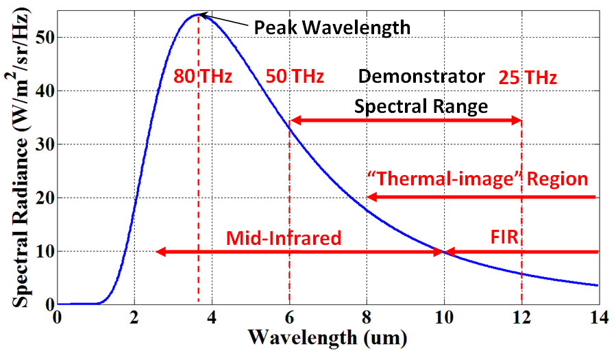
Figure 11. Ideal spectral emissivity fitting curve versus wavelength at 772K operating temperature
(2) Basic receiver subsystem.
As shown in Figure 12 for the pyroelectric sensor used in the system, the pyroelectric sensor detects objects by measuring the temperature difference between the target and the background. The thermopotential material produces a spontaneous polarized charge and produces different amounts depending on the temperature of the material.
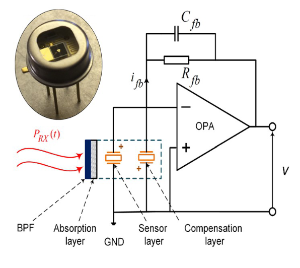
Figure 12. LME-553Sensor and its circuit
The change in temperature caused when incident radiation flux \( {Φ_{S}}[W] \) is received by the sensor can be expressed by the following equation
\( ΔT=α\frac{{Φ_{S}}}{{G_{T}}}\frac{1}{\sqrt[]{1+{(ω{τ_{T}})^{2}}}} \)
Where \( α \) is the absorption efficiency; \( { τ_{T}}=\frac{{H_{p}}}{{G_{T}}} \) is thermal response time; \( {H_{p}} \) and \( {G_{T}} \) is the heat capacity and thermal conductivity of the sensing material, respectively.
4.3. First single-channel “Terahertz Torch” principle demonstrator
As shown in Fig. 13, it realizes a basic single-channel architecture. Its transmitter and receiver are separated by 0.5 cm, with which a short-range line-of-sight visible wireless communication link is established.
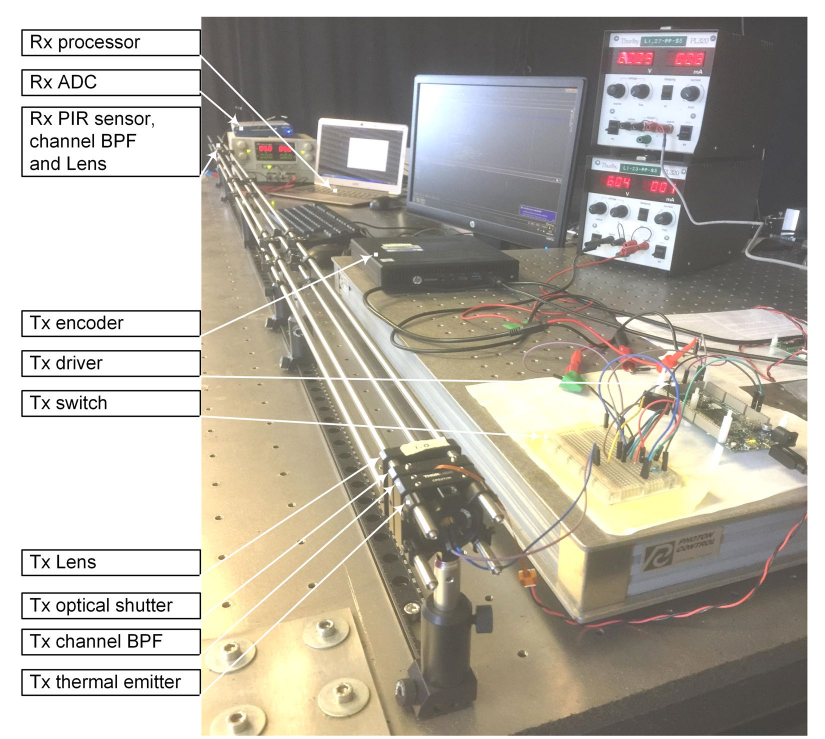
Figure 13. Demonstration of experimental setup
The experimental results show that the maximum bit rate is 5b/s at a transmission distance of 0.5cm, as shown in Fig. 14.a. The bit rate decreases drastically with increasing distance, the main reason for which the authors attribute to beam scattering and atmospheric absorption losses. Also as seen in Fig. 14.b, an increase in the number of light bulbs in series increases the maximum transmitted bit rate at a given distance, while saturation occurs when three are reached.
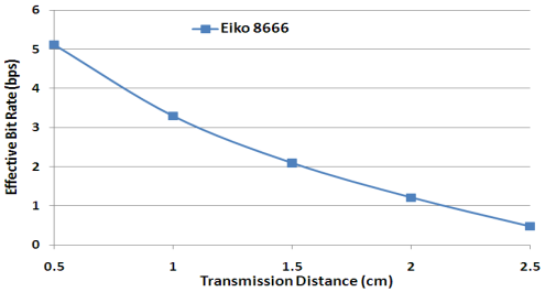
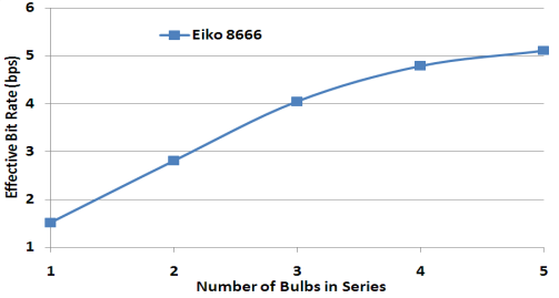
Figure 14. (a) Transmission distance; (b) Curve of number of bulbs versus effective bit rate
Not only that, the authors also expand the single path to multiplexing to realize frequency division multiplexing (FDM) and frequency hopping spread spectrum (FHSS). This further enhances the anti-jamming capability of the system. In the future, more channels may be added to the terahertz torch FDM program.
The system successfully realizes and demonstrates an ultra-low cost short-range secure wireless communication system that shows easy production, ultra-low intrinsic cost, wireless transmission, and many other features. Although there are limitations in practical application due to low bit rate, free space loss, expansion loss, bulb absorption, light scattering, microphony, and many other problems, the technology has advantages that other RF bands do not have. Advantages can be foreseen in the security of RFID, security data transmission, enemy identification, etc.; they do not need a high data rate and a close range of security information in the field of great color.
5. Conclusion
This review elaborates the unique physical properties of electromagnetic waves in the terahertz frequency band and the advantages and disadvantages of the corresponding applications; it also briefly summarizes the origin and development of the modern terahertz technology and improves the knowledge of the terahertz technology; and takes the thermal infrared-based “terahertz torch” technology as an example to illustrate the development of the cutting-edge terahertz technology as well as its limitations and future development direction. The results show that Terahertz technology, as an emerging field, has made remarkable progress in the past decades, and has shown great potential in the fields of communication, imaging and detection. However, terahertz technology still faces some limitations and challenges. Due to the large atmospheric attenuation of terahertz wave, along with the transmission distance is limited, which restricts its scope of application in communication and imaging applications. And terahertz technology in the choice of materials, there are also difficulties, the traditional electronic and optical materials in the terahertz frequency band absorption and scattering is large, affecting the signal transmission and detection effect; corresponding to the high cost in industrial production. The complexity of high-frequency electronic devices and the fabrication of devices technology has led to the high cost of terahertz equipment and systems, limiting the development of its commercialization and large-scale applications.
And in the future, the problem of attenuation should be solved firstly to improve its transmission distance and signal quality in order to expand its application range. Secondly, develop new terahertz materials with low absorption and scattering properties to improve signal transmission and detection. In addition, reducing the cost of terahertz equipment and systems is also an important development direction, which can be realized through integration and mirco-nanofabrication technology.
In conclusion, terahertz technology has made remarkable progress in the past decades, showing a broad application prospect. Although there are still some limitations and challenges, through improvements and innovations, terahertz technology is expected to play a greater role in the fields of communication, imaging, and detection. Future directions include improving transmission distance and signal quality, developing new terahertz materials, and reducing costs, which will facilitate the further application and commercialization of terahertz technology.
This review only introduces the tip of the iceberg that the Tamples and its application, and cannot be described completely; if the reader wants to have more understanding of it, it needs more related literature reading.
References
[1]. YU L, HAO L, MEIQIONG T, et al. The medical application of terahertz technology in non-invasive detection of cells and tissues: opportunities and challenges [J]. RSC Advances {ISSN}, 2019,9(17): 9354-9363.
[2]. CARLO CORSI, SIZOV FEDIR. THz and Security Application: Detectors, Sources and Associated Electronics for THz Applications. 2019:9.
[3]. CHAMBERLAIN J M. Where optics meets electronics: recent progress in decreasing the terahertz gap [EB/OL]. https://doi.org/10.1098/rsta.2003.1312.
[4]. SHUR M. Terahertz_Electronics [J]. 2008.
[5]. M. C K. Millimetre wave and terahertz technology for detection of concealed threats - a review: 2007 Joint 32nd International Conference on Infrared and Millimeter Waves and the 15th International Conference on Terahertz Electronics [C], 2007.
[6]. ZUBOV A. Spectral [J]. Science Fiction Film and Television, 2019,12(2): 297-302.
[7]. WOOD R A. Integrated uncooled infrared detector imaging arrays [J]. IEEE, 1992.
[8]. REN H, LUCYSZYN S. Thermodynamics-based Cognitive Demodulation for ‘THz Torch’ Wireless Communications Links [J]. Scientific Reports, 2020,10(1).
[9]. LUCYSZYN S, LU H, HU F. Ultra-low cost THz short-range wireless link: IEEE, 2011.
Cite this article
Yu,D. (2024). Research on the application of the terahertz technique. Applied and Computational Engineering,62,198-210.
Data availability
The datasets used and/or analyzed during the current study will be available from the authors upon reasonable request.
Disclaimer/Publisher's Note
The statements, opinions and data contained in all publications are solely those of the individual author(s) and contributor(s) and not of EWA Publishing and/or the editor(s). EWA Publishing and/or the editor(s) disclaim responsibility for any injury to people or property resulting from any ideas, methods, instructions or products referred to in the content.
About volume
Volume title: Proceedings of the 2nd International Conference on Mechatronics and Smart Systems
© 2024 by the author(s). Licensee EWA Publishing, Oxford, UK. This article is an open access article distributed under the terms and
conditions of the Creative Commons Attribution (CC BY) license. Authors who
publish this series agree to the following terms:
1. Authors retain copyright and grant the series right of first publication with the work simultaneously licensed under a Creative Commons
Attribution License that allows others to share the work with an acknowledgment of the work's authorship and initial publication in this
series.
2. Authors are able to enter into separate, additional contractual arrangements for the non-exclusive distribution of the series's published
version of the work (e.g., post it to an institutional repository or publish it in a book), with an acknowledgment of its initial
publication in this series.
3. Authors are permitted and encouraged to post their work online (e.g., in institutional repositories or on their website) prior to and
during the submission process, as it can lead to productive exchanges, as well as earlier and greater citation of published work (See
Open access policy for details).
References
[1]. YU L, HAO L, MEIQIONG T, et al. The medical application of terahertz technology in non-invasive detection of cells and tissues: opportunities and challenges [J]. RSC Advances {ISSN}, 2019,9(17): 9354-9363.
[2]. CARLO CORSI, SIZOV FEDIR. THz and Security Application: Detectors, Sources and Associated Electronics for THz Applications. 2019:9.
[3]. CHAMBERLAIN J M. Where optics meets electronics: recent progress in decreasing the terahertz gap [EB/OL]. https://doi.org/10.1098/rsta.2003.1312.
[4]. SHUR M. Terahertz_Electronics [J]. 2008.
[5]. M. C K. Millimetre wave and terahertz technology for detection of concealed threats - a review: 2007 Joint 32nd International Conference on Infrared and Millimeter Waves and the 15th International Conference on Terahertz Electronics [C], 2007.
[6]. ZUBOV A. Spectral [J]. Science Fiction Film and Television, 2019,12(2): 297-302.
[7]. WOOD R A. Integrated uncooled infrared detector imaging arrays [J]. IEEE, 1992.
[8]. REN H, LUCYSZYN S. Thermodynamics-based Cognitive Demodulation for ‘THz Torch’ Wireless Communications Links [J]. Scientific Reports, 2020,10(1).
[9]. LUCYSZYN S, LU H, HU F. Ultra-low cost THz short-range wireless link: IEEE, 2011.