


1. Introduction
With the increasing number of populations, people are increasingly dependent on electricity. However, the issue related to how to solve environmental problems is also an important topic, the environmental impact of the utility of traditional energy sources like coal, oil cannot be ignored, taking thermal power generation as an example, China’s thermal power generation accounts for 41% of the energy sector’s carbon emissions, which can make a huge influence for the air quality. The use of new energy sources like solar photovoltaic power generation, ocean energy, geothermal energy and wind energy is more environmentally friendly and efficient [1-3]. Also, the emergence of new energy vehicles (such as pure electric vehicles, hybrid vehicles, solar vehicles, and fuel vehicles) has made it possible to use energy efficiently. The advantages of new energy vehicles include lower emission (such as hydrogen cars emit water, electric vehicles have no gas emissions), generate lower levels of noisy [5-6]. More importantly, compared to traditional internal combustion engine, the new energy vehicles have a higher energy utilization rate (generally using hydrogen energy, natural gas, electric energy, etc.) In recent years, more and more public transportations like bus, taxi take the mode of “pure electric”. In Europe, the amount of city tram system is constantly rising. Take pure electric vehicles for example, the basic structure of DC charging is shown in Figure 1.
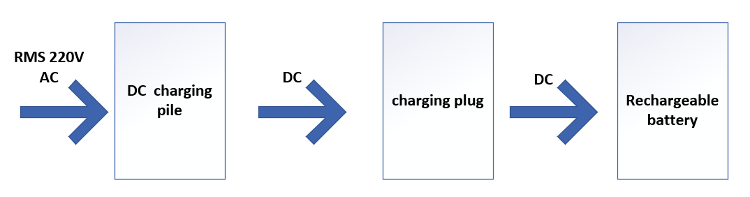
Figure 1. Basic diagram of an electric vehicle charger [4].
In the DC charging pile, the rectifier coverts the 220V AC (supplied by national grid) to DC, then the rechargeable battery is charged through the charging plug. But in actual process of rectification, the influence of the inductive and capacitive reactance of the actual circuit on the power factor will further affect the efficiency of charging, so power factor correction (PFC) technology was proposed in the 1950s, the aim of it is to adjust the input current wave also avoid the active power loss caused by the low value of power factor. It also avoids heat dissipation problems due to the high-power factor, more importantly, reduces the phenomenon of harmonics in the circuit as well as solve the issues related to electromagnetic compatibility (EMC). As for the PFC technology, there are two common ways: active power factor correction (APFC) and passive power factor correction (PPFC) [6-10].
Based on existing research results, this essay provides an overview of single-phase rectifier circuits (including half-wave rectifier, full-wave rectifier, and bridge rectifier) and passive power factor correction.
2. Single-phase half-wave rectifier circuits
2.1. Half-wave rectifier circuit with resistance load
Most forms of AC are sinusoidal, using the ideal diode’s characteristic of “forward voltage drop is 0 and reverse impedance is ∞”, a basic resistive load circuit has been designed as shown in Figure 2.

Figure 2. Diode-based Half-wave rectifier [4]
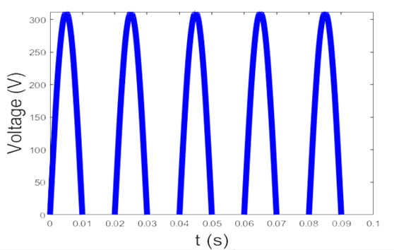
Figure 3. Waveform of half-wave rectifier circuit [2]
The diode conducts when the AC voltage source is in the positive half cycle; conversely, the diode is in the cut-off state, and no current passes through the resistor. This circuit has the advantage of simple structure and it is easy to construction, but disadvantage is that its output pulse is too big, and the output wave cannot be controlled. The measured waveform (voltage versus time) is shown in Figure 3. If the diode is replaced by the thyristor (as shown in Figure 4), the circuit achieves the semi-control function.
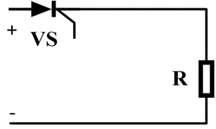
Figure 4. Thyristor rectifier with R load [2]
Thyristor is a semi-controlled electronic device, which has anode, cathode and gate. In order to conduct it, besides the need to add the positive voltage to the anode, the pulse signal also needs to be added to the gate, the value of the control angle is changed by changing the pulse signal, then controls the output voltage waveform. When the input voltage is in the negative half-cycle, no current passes through the load R. When the input voltage is in the positive half-cycle, if no pulse signal is applied to the gate, the entire circuit will still remain the state of no current. Setting the control angle of VS shown in the figure 4 is α, during the range of (α, π), the thyristor conducts and current flows through the load R. The gate of thyristor has the “switch” fundamental, the magnitude of the conduction angle α is controlled by varying the monument of when applying the pulsed voltage signal, which in turn controls the time interval of conduction and finally the average power at the load will be adjusted, too. However, the thyristor can just control the circuit conduction but not the open of it, thus it a type of semi-controlled circuit.
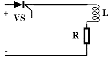
Figure 5. Thyristor rectifier with RL load [3]
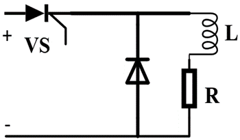
Figure 6. Thyristor-diode rectifier with RL load [3]
2.2. Half-wave rectifier circuit with Resistance-Inductance load
For inductive load, the voltage waveform leads the current waveform, when the input voltage just at the instant when the positive half-cycle changes to the negative half-cycle, the inductor can discharge, in this case the thyristor conducts (the ideal thyristor is equivalent to an ideal wire, no resistance). At this point, there is voltage at the load, even though the input voltage is in the negative half-cycle. Compared to resistive loads, resistance-induction load delays the turn-off monument of thyristor, but the output voltage has a negative area, which reduces the average value of the output voltage [3].
As shown in Figure 6, if paralleling a diode in front of the load, the issue can be solved, because when the inductor is discharging, the current can pass through the diode, It has no effect on the thyristor. Since the thyristor does not conduct, the output voltage waveform at the Resistance-Inductance load is the same as that at the resistance load.
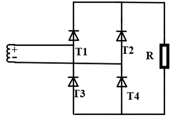
Figure 7. Full-bridge rectifier [4]
3. Single-phase bridge full-wave rectifier circuit
As shown in Figure 7, in this circuit, the diode T1 and T4 belong to a group, T2 and T3 belong to a group, when the supply voltage is in the positive half cycle, diode T1&T4 conduct, and current flows through T1 and resistor, finally back to the negative terminal, when the supply voltage is in the negative half cycle, diode T2 and T3 conduct, and current flows through T2 and resistor, finally back to the negative terminal.
Ignoring the positive voltage when diode is conducting, the voltage at the load is always same as that at the secondary transformer, thus it greatly increases the average power of the load, but the material cost is higher than that of the single-phase half-wave rectifier circuits. What truly matters is that diode is also uncontrollable device and this circuit belongs to uncontrollable circuit.
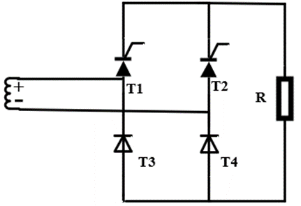
Figure 8. Semi-controlled rectifier [3]
4. Single-phase bridge semi-controlled rectifier circuits
As shown in Figure 8, the use of two thyristors and two diodes in this circuit achieves semi-control of the circuit. When the input voltage is in the positive half-cycle, T1 applies a pulse signal and the current flows through the load and diode T4; whereas when the input voltage is in the negative half-cycle, T2 applies a pulse signal and the current flows through the load and diode T3, which achieves semi-control of the full-wave rectification.
Compared with the half-wave rectifier circuit, the bridge rectifier circuit has a higher utilization of the input voltage, and for the transformer, because there is no center tap, there is positive voltage at the load from time to time. and the output waveform is smooth and stable [4]. Also, the output pulse fluctuation is relatively small, but this kind of circuit is only suitable for low power loads.
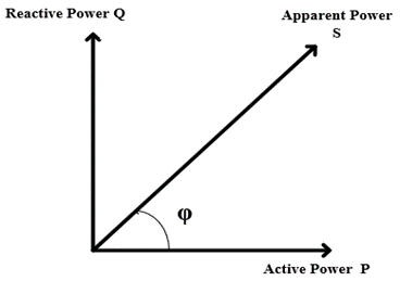
Figure 9. Power factor [6]
5. Passive Power Factor Correction
The rectification method mentioned before is only in the ideal state of the situation. Generally speaking, the current after the rectification cannot up to the quality criteria, it is mainly because during the actual process, the harmonics of the grid and the inductance of the wire are not negligible, which always affects the power factor cosφ, as shown in Figure 9, if the value of it is too high, it will increase the power of the heat, bringing potential safety hazards, by contrast, if the value is too low, it will affect the power transmission.
In recent years, various active power factor correction circuits have been designed to keep the power factor at a suitable value, which is suitable for high-power loads such as electric vehicles, but the lack is that the stability of the circuit is reduced, as a result, it makes certain economic losses. Passive power factor correction is using passive devices (diodes, capacitors, inductors, etc.) to correct the power factor, the circuit of it generally has simple structure, it is also easy to design, but the disadvantage is that it is only suitable for low-power loads.
The use of inductors can make the power factor lagging, while the use of its feature: “voltage can not be changed suddenly” to ease the pulse signal, so that the waveform of the output voltage is smoother; and using the capacitor’s property that the voltage change across the capacitor lags the current change, it can be connected in parallel in front of the load to improve the power factor.
6. Summary
This essay is a review of the basic single-phase rectifier circuit topology, analyzed from the perspective of output waveform and their own application. Whereas, basically, a significant issue of the rectifier is the large output pulse, we need to pay attention to the voltage range that diode & thyristor can withstand. In addition, harmonics is also an important influence on the rectifier, so the rectifier should be combined with the field of filtering and PFC technology, based on it, we also need to consider the need of the industry. In the future, co-operation between the automation field and the power grid field, along with the combined use of circuit topologies such as Boost and Buck will accelerate the development of rectification technology.
References
[1]. Wu Guijun, Lei Yong. Single-Phase Rectifier Filter Circuit. Science and Technology Information, 2012(33): 154.
[2]. Niu Jingchuan. Application of Single-Phase Phase-Controlled Rectifier Circuit. Silicon Valley, 2012, 5(16): 146-147.
[3]. Hu Tianzi. Development of Single-Phase Rectifier Circuits. China Science and Technology Information, 2019(24): 33-34.
[4]. Wang Ruidong. A Brief Discussion on Several Types of Uncontrolled Single-Phase Rectifier Circuits. Science and Technology in China, 2017(02): 60.
[5]. Sun Yijie. Research on Passive PFC Converter with Wide Input Voltage Range [D]. Southwest Jiaotong University, 2022.
[6]. Huo Zhaojing, Bi Ran. An Efficiency-Optimized High-Frequency PFC Control Method. Household Appliances Technology, 2023(01): 88-91+96.
[7]. Xie Jiakui. Nonlinear Components of Electronic Circuits [M]. 4th Edition. Beijing: Higher Education Press, 2012: 54-56.
[8]. Song Pingang, Lian Jiawei, Chen Yi. A Novel Direct Power Control Strategy for Single-Phase Power Electronic Transformer Rectifier Stage. Control Theory and Applications, 2022, 39(03): 402-410.
[9]. Luo Yuefang, Bai Zelong, Li Jicheng, et al. Comparative Study of Single-Phase Bridge Fully Controlled Rectifier and Single-Phase Half-Wave Controllable Rectifier Circuits. Electronic Technology and Software Engineering, 2023(07): 86-89.
[10]. Zhao Qiuyu, Cai Mengzhe, Gao Han, et al. Research and Analysis of Single-Phase Uncontrolled Rectifier Circuit with Capacitor Filtering. Journal of Xuchang University, 2020, 39(05): 114-118.
Cite this article
Zhai,S. (2024). Recent advances in single-phase rectification methods. Applied and Computational Engineering,62,271-276.
Data availability
The datasets used and/or analyzed during the current study will be available from the authors upon reasonable request.
Disclaimer/Publisher's Note
The statements, opinions and data contained in all publications are solely those of the individual author(s) and contributor(s) and not of EWA Publishing and/or the editor(s). EWA Publishing and/or the editor(s) disclaim responsibility for any injury to people or property resulting from any ideas, methods, instructions or products referred to in the content.
About volume
Volume title: Proceedings of the 2nd International Conference on Mechatronics and Smart Systems
© 2024 by the author(s). Licensee EWA Publishing, Oxford, UK. This article is an open access article distributed under the terms and
conditions of the Creative Commons Attribution (CC BY) license. Authors who
publish this series agree to the following terms:
1. Authors retain copyright and grant the series right of first publication with the work simultaneously licensed under a Creative Commons
Attribution License that allows others to share the work with an acknowledgment of the work's authorship and initial publication in this
series.
2. Authors are able to enter into separate, additional contractual arrangements for the non-exclusive distribution of the series's published
version of the work (e.g., post it to an institutional repository or publish it in a book), with an acknowledgment of its initial
publication in this series.
3. Authors are permitted and encouraged to post their work online (e.g., in institutional repositories or on their website) prior to and
during the submission process, as it can lead to productive exchanges, as well as earlier and greater citation of published work (See
Open access policy for details).
References
[1]. Wu Guijun, Lei Yong. Single-Phase Rectifier Filter Circuit. Science and Technology Information, 2012(33): 154.
[2]. Niu Jingchuan. Application of Single-Phase Phase-Controlled Rectifier Circuit. Silicon Valley, 2012, 5(16): 146-147.
[3]. Hu Tianzi. Development of Single-Phase Rectifier Circuits. China Science and Technology Information, 2019(24): 33-34.
[4]. Wang Ruidong. A Brief Discussion on Several Types of Uncontrolled Single-Phase Rectifier Circuits. Science and Technology in China, 2017(02): 60.
[5]. Sun Yijie. Research on Passive PFC Converter with Wide Input Voltage Range [D]. Southwest Jiaotong University, 2022.
[6]. Huo Zhaojing, Bi Ran. An Efficiency-Optimized High-Frequency PFC Control Method. Household Appliances Technology, 2023(01): 88-91+96.
[7]. Xie Jiakui. Nonlinear Components of Electronic Circuits [M]. 4th Edition. Beijing: Higher Education Press, 2012: 54-56.
[8]. Song Pingang, Lian Jiawei, Chen Yi. A Novel Direct Power Control Strategy for Single-Phase Power Electronic Transformer Rectifier Stage. Control Theory and Applications, 2022, 39(03): 402-410.
[9]. Luo Yuefang, Bai Zelong, Li Jicheng, et al. Comparative Study of Single-Phase Bridge Fully Controlled Rectifier and Single-Phase Half-Wave Controllable Rectifier Circuits. Electronic Technology and Software Engineering, 2023(07): 86-89.
[10]. Zhao Qiuyu, Cai Mengzhe, Gao Han, et al. Research and Analysis of Single-Phase Uncontrolled Rectifier Circuit with Capacitor Filtering. Journal of Xuchang University, 2020, 39(05): 114-118.