


1. Introduction
1.1. General Background
In an effort to address the mobility challenges of the 253 million people globally affected by visual impairment, our team is developing an innovative product aimed at enhancing the independence and quality of life for this demographic. Our solution stands out in the current market by offering a user-friendly and multi-functional navigation aid that prioritizes safety, ease of use, and efficient route planning, fostering greater confidence and reducing accident risks for visually impaired individuals. This endeavor represents a step towards a future where visual impairment does not significantly limit personal autonomy [1].
1.2. Problem Statement
Urban road planning is becoming increasingly complex with the rapid development of science and technology in today’s world. At the same time, the types of transportation have become very diverse. Under the new urban road planning, more and more intersections and traffic lights appeared. Although this contributes to the development of urban transportation, it has caused significant obstacles to the travel of vision-impaired people. The constantly updated roads make it difficult for vision- impaired people to plan travel routes. Faster modern vehicles, crossroads and roadside obstacles threaten the safety of vision-impaired people while walking independently. Because of the above situation, we have analyzed several problems that the manufactured products must solve [2]. To help visually impaired people reduce the safety hazards of travel independently, the most important problem is how to give early warning and help vision-impaired people avoid obstacles. While walking without any aids, it is impossible for a vision-impaired person to see the approaching obstacle like a normal person and take action in advance to change the direction of travel and even avoid it. When we are designing a product, we must not only consider whether its function is practical, but also whether the product is beautiful in appearance and whether it is convenient for consumers to use. Through the survey of other similar products on the market, the actual feedback of users’ experience is generally that the product lacks convenience. The hands are completely restrained when using the guide cane. At the same time, some other products also restrict users’ freedom to varying degrees. In response to the problems above, we decided to make some improvements in the products we are going to design.
1.3. Design Goals
In order to solve the problem of how to help visually impaired people avoid obstacles as well as moving pedestrians and vehicles before a collision occurs [3]. We need to use several components like camera, GPS and vibrator. Cameras capture and identify people and objects in front of and behind the user. Mainboard analyzes a series of images captured, identifies stationary obstacles and moving objects. Predict and simulate the trajectory path of moving objects and calculate the speed of movement. The user’s position is detected by GPS at regular intervals, expressed and recorded by latitude and longitude coordinates. A user’s movement trajectory is simulated through several coordinates [4]. Comparing the two simulated paths, in the event of a collision, the motherboard will generate a signal to activate the vibrating device as a warning until the possibility of a collision disappears. We installed a total of six vibrators on our product to provide the possible collision directions as accurately as possible. The success of our project is that the camera can identify objects, GPS can detect position coordinates, and the program can simulate the predicted trajectory path. When a collision is predicted, a signal is generated and drives the vibration motor in the corresponding position to start vibrating. Also, in order to improve the portability and comfort of the product, we will not use the traditional blind cane design. We designed it as a wearable vest. This design can completely liberate the user’s hands and greatly improve portability.
2. Design
2.1. Discussion of Designing Process
Our initial idea was to use a wearable sports vest. A camera was installed in the center of the front to identify people and objects ahead. Three distance sensors were installed under the camera and on both sides of the vest to measure the distance between obstacles in front of the user and on the left and right sides of the user. Several vibrators were mounted under the vest straps. When the distance sensor detects that the distance between the obstacle and the user is less than a critical value, the vibrator would start to work. The motherboard and battery were mounted on the back. This design can concentrate the entire system on a single vest, but the disadvantages are also obvious. The sensors on both sides are easily blocked by the users’ arms. In addition, the vibration sense is not obvious due to the influence of clothes thickness.
Therefore, we considered changing the position of the sensors and vibrators [5]. Our subsequent idea was to design a sliding bracket on the shoulder strap for the sensors which were originally on the sides. Users can also adjust the sensor position according to individual body type differences. We want to place the vibrator as close to the skin as possible. So we decided to separate the vibrating part from the vest and make two vibrating bracelets. The user can figure out the position of the obstacle by sensing the vibration of the left and right wrists. However, after consideration, this design still has some shortcomings. Vibration on the wrist is obviously a burden to the user. Our original intention is to free the hands of users. This idea obviously goes against the original intention. Sensors located on the shoulder are limited by the angle and cannot exert its maximum value and the test results cannot meet our requirements. So, we decided to add an exercise waist belt and move vibrators into the belt. The waist belt is used in conjunction with the vest. Users can figure out the position of obstacles by sensing the vibrating parts on the belt. The number of vibrators in the belt was determined to be six. Six vibrators are evenly distributed to accurately reflect obstacles from different directions [6]. This design greatly enhances the aesthetics of the product, and also improves the user’s wearing experience, so that the sense of vibration can be clearly transmitted to the user.
For distance sensors, we finally decided to give up the use of tasteless sensors. Accordingly, we added another camera on the back. Therefore, we need to upgrade the quality of our cameras to increase the visibility of the cameras. We ended up choosing two 1080p webcams for our product.
Regarding the motherboard, at the beginning we decided to install two microprocessors, Raspberry Pi 3, to process the images captured by the two webcams on the front and back. But after the Alpha prototype testing [7], we realized that the Raspberry Pi lacks computing power. Finally, we upgraded our board to an NVIDIA Jetson TX2 development board. We installed it on the back together with a 12V 7AH Lithium Battery as its power source.
2.2. Final Design
We will use two webcams, Jetson TX2, GPS module power supply and vibration motors. We will place them on a vest and a waist. The product can predict the trajectory of obstacles and users and determine whether there will be an intersection. The vibration motors one the waist will remind users of the direction of the obstacles. The advantage is that it can accurately predict the direction and distance of obstacles, while the disadvantage is that Jetson’s limited computing power may lead to insufficient alarm time.
2.3. Backup Plans
Our backup plan from last semester was about some of the constraints we encountered. One is that we chose a 2D fish-eye camera with no built-in depth of field. During the coding process, the coding amount of the depth of field will be greatly increased, and it is highly uncontrollable. Another is the huge workload of the code. We need to implement three major code function modules: obstacle recognition, trajectory prediction and relative motion position and velocity analysis. Our plan is that if the code effort is too large for a 2D camera, we can opt for a 3D camera, which has its own depth of field and saves a bit of code analysis. In addition, for image distortion, we can write a specific function to solve this problem, convert the distorted image into a normal image and analyze it. These plans were adopted or replaced as we changed cameras and processors. Specifically reflected in technical analysis and Alpha & Beta testing section.
3. Analysis
In the analysis stage, we made a detailed analysis of the prototype and software requirements of the whole product, as shown in the Table 1 below:
Table 1. Final Parameters Specification
METRIC | UNITS | VALUES |
Total mass | kg | < 7 |
Vibration motor speed | rpm | 6000 |
Vibration motor voltage supply | V | 5 |
Battery voltage | V | 12 |
Duration of battery single using | h | 10 |
Camera voltage input | V | 4 − 8 |
Camera detection distance range | m | 0.5 − 30 |
Vertical detection angle range | deg | -45 − 45 |
Horizontal detection angle range | deg | -60 − 60 |
Camera detection frequency | FPS | 1 − 3 |
Camera feedback time | s | 0.5 − 1.5 |
Product affordable force | N | < 100 |
GPS positioning error | m | < 5 |
Product surface material | – | waterproof & breathable |
Sale price | $ | 649 |
These established parameters determine that our design will use two cameras and six vibrators. The weight of the whole product is just suitable for one person to wear, which will not affect the walking speed or be too light to cause discomfort. The product needs enough space to place the processor and the power supply, so it’s best to take the shape of clothes and put the power supply and the processor inside the clothes. We installed a camera on the chest and back respectively, and sewed all the wires in the clothes, which not only ensured the connection between various components, but also ensured that they would not be damaged by external forces [8]. The product needs enough space to place the processor and the power supply, so it’s best to take the shape of clothes and put the power supply and the processor inside the clothes. We installed a camera on the chest and back respectively, and sewed all the wires in the clothes, which not only ensured the connection between various components, but also ensured that they would not be damaged by external forces.
For our initial schematic, our software requirements and hardware requirements can be met in Fig. 1. The transmission of signals is very orderly, and the hardware can be well protected, which solves the problem of being damaged by external impact.
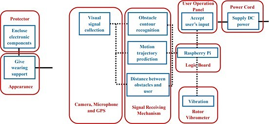
Figure 1. Schematic of the Product
4. Alpha Prototype
4.1. Alpha Prototype Construction
In the process of building the Alpha prototype, we mainly focus on the compilation and modification of some basic functions. We use raspberry pi to realize the functions of object recognition and GPS track recording shown in Fig. 2.
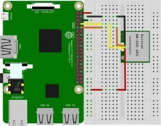
Figure 2. Alpha Prototype: Camera and GPS Connection
In the object recognition function, we use a database named tensorflow, which contains data of about 90 kinds of objects. We imported it and compiled it, and it worked as smoothly as we expected. The system correctly displays the captured images and clearly marks the names and similarities of the recognized objects, but there are still several shortcomings. First, it can’t show the relative position between the identified object and the screen picture. Second, the frame rate of the camera capturing pictures will be very low, about 1fps because the data is analyzed in real time. For these two problems, we have made corresponding improvements to the code.
First of all, we read the description of the database and found that there are actually data that can indicate the relative position, that is, the bounding box of the object. After deeply understanding its operation mechanism, we extracted the positions of the four vertices of the bounding box from the array and named them with different variables. The variables of these four vertices include their relative positions to the screen. For this reason, we multiply the relative position by the pixel height and width of the picture to get the relative position and pixel height of the bounding box. After getting the pixel height, we use the rule of triangulation, and multiply the focal length by the actual height divided by the pixel height to get the actual distance between the object and the user.
As for the low frame rate, because of the large database and high hardware requirements, we can only reduce the size of the picture from 1280*720 to 640*480. After improvement, the frame rate has been able to reach 2 FPS. In the GPS track recording part, we connect the GPS chip and raspberry pi as shown in the figure. When the blue light flashes, it means that the circuit is connected correctly and can start working. The chip needs to be in an open place to receive satellite signals. When it receives signals well, the red light will flash.
4.2. Alpha Prototype Testing
In the alpha test, we mainly complete two tests [9], the first is the accuracy of object recognition, and the second is the feasibility of GPS to record the user’s trajectory. All testing time are 300 seconds. First is the accuracy of object recognition, we used the written program to recognize pedestrians on campus, and made a table, which recorded the status of all pedestrians (near and still, far and still, near and moving, far and moving) and the recognition results (Table II and Table III). Fig. 3 is the figure shows how recognition looks like, and through binomial distribution, the recognition accuracy and error values of all different situations were calculated in Fig. 4. The conclusion showed that the actual situation was within the predicted range, and the recognition accuracy was high.
Table 2. Pedestrians Recognition Record
Pedestrian (Condition) | Detected |
Pedestrian 1 (FS) | Yes |
Pedestrian 2 (NM) | Yes |
Pedestrian 3 (NS) | No |
Pedestrian 4 (FM) | Yes |
. . . | . . . |
{N: near, F: far, M: moving, S: static}
Table 3. Correct Recognition Probabilities
Pedestrian (Condition) | Probability |
Pedestrian (NM) | 73/77 = 0.9481 |
Pedestrian (NS) | 35/39 = 0.8974 |
Pedestrian (FM) | 38/46 = 0.8261 |
Pedestrian (FS) | 18/22 = 0.8182 |
Total | 164/184 = 0.8913 |
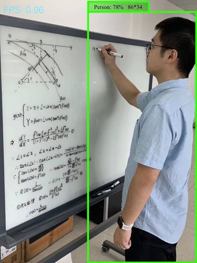
Figure 3. Human Recognition Rendering
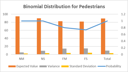
Figure 4. Binomial Distribution Analysis
For GPS track recording, we use the BN220 GPS chip, and its distance error can be controlled within 2m. There are four pins in the chip, namely GND, TX, RX and VCC from left to right, which are connected to the pins of raspberry pi in sequence. We have written the code to extract the current latitude and longitude of the user every ten seconds and replace the coordinates in the original two matrices and draw the two coordinates in a straight line on the map of the HTML file, as shown in Fig. 5.
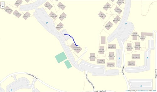
Figure 5. GPS Trajectory Recording
For the whole alpha test, what we can improve is the object recognition function. The result of the low frame rate is that capturing images is slow, but the road conditions are changing rapidly [10]. So we hope to modify the code logic, changing the real-time analysis into storing images first, and then using script analysis in the background, which can greatly reduce the interval time between capturing images and reduce the memory occupation of raspberry pi.
According to all the feedback from the alpha test, our product is feasible at present, because all the data analysis and target functions can be well realized, and the calculation results can be obtained in a small error time.
5. Beta Prototype
5.1. Beta Prototype Construction
In the Beta prototype, for the first step, we are going to build the actual electrical circuit of this system. All of the required hardware here includes one GPS module, six vibrating mini motors and two USB cameras. The power for Jetson board is about 19 volts. The approach for connecting a vibrating mini motor is for GPIO control, since the supply voltage is over the maximum value of it, a protecting register is necessary for each branch. In terms of GPS, it is working with serial communication. As it’s shown in Fig. 6 below, this is the working circuit of the whole system.
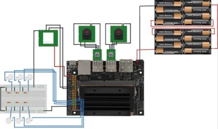
Figure 6. Electrical Circuit of System
5.2. Beta Prototype Testing
Here is the part of Beta Testing. We were focusing on getting more tests on the prediction of trajectory and sending out the warning signals from the system to the users. To achieve the prediction of trajectory of objects, we were using a neural network that is based on the mathematical model of probability contribution. The theory of how this neural network works is to estimate the final destination and to record the past specific-duration trajectory, and then to analyze the future prediction. In order to get this neural network working for the test on prediction on trajectory, we need our own dataset. Therefore, initially, we took a video of objects on the road for processing through the test. Next, the dataset for neural network is accumulated with RGB pixel values of a bunch of images. There are built-in functions from Open CV library to convert a video to a set of RGB values. About this dataset, it is created with 30 frames of a video, and each frame is with a resolution of 640*480 pixels. Finally, we should get a set of data as shown in the Table below.
Table 4. Example of RGB Pixel Values
75 | 43 | 44 |
94 | 60 | 61 |
78 | 42 | 44 |
80 | 39 | 43 |
102 | 60 | 64 |
96 | 51 | 56 |
Table 5. ADE & FDE for Prediction of Trajectory
Average ADE | 17.378018939916593 |
Average FDE | 35.37710504579852 |
Once we get the dataset, then we can import it into a neural network and do training for prediction of trajectory. In order to acquire a good performance of the result of the neural network, we set up the number of epochs as 650, which means how many cycles the neural network did for training. After completing the process of training, we get two values of error for prediction of trajectory, Average Displacement Error (ADE) and Final Displacement Error (FDE), which stands for the percentage of error with respect to the actual position. These two values are listed in Table V above.
In addition, we also acquired the data of prediction of trajectory, we need to plot it as well as plotting trajectory of the User from GPS. However, the result of data from a neural network is a 3D tuple, but data from GPS is a 2D array. In order to be able to plot both two on the same graph, we have to convert the 3D tuple to a 2*2 array as the first step. Then, we assume that x-axis is latitude and y-axis is longitude. We get the plot as shown in Fig. 7
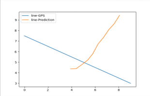
Figure 7. Plot of User’s & Object’s Trajectory
By then getting the information if two trajectories are intersected or not, which is the key command to activate the vibrating motor to send out the warning signal. However, specifically which vibrating motor will be activated? In other words, what is the direction of objects coming from? This is controlled by the information from the bounding box in the part of object recognition. Bounding box tells us what the vectors of positions are in terms of upper- left point and low-right point. With both two vectors of positions and revolution of image, we can decide where the object is coming from. The conditions of control are shown as Fig. 8 below.
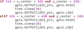
Figure 8. Conditions for Motors Controlling
6. Final Product Design
After several iterations of design ideas, our final design is shown in Fig. 9 and Fig. 10 below. The materials we used for our final design were an Nvidia Jetson TX2 development board, two 1080p webcams, a GPS component, a bulletproof vest, a sports belt, a 12V 7AH Lithium Battery, and six vibrator motors.
Two webcams are mounted on the front and rear center of the vest. The NVIDIA Jetson TX2 development board and battery are mounted below the webcam on the back. Six vibration motors are mounted evenly on the belt. All the cables go through the inter layers of the vest fabric and are reinforced through sewing. The positive and negative wires of six vibration motors are assembled and connected to the Jetson TX2 board. The webcam captures people and objects within its visual range and passes a series of image data to the Nvidia Jetson TX2 development board. Jetson then analyzes the series of images, simulates the motion trajectories of front and rear pedestrians and objects, and calculates their speed.
GPS detects the user’s position and outputs it in the form of latitude and longitude coordinates. Jetson simulates the user’s movement trajectory and speed through the series of coordinates. Jetson plots several simulated trajectory paths on a single plot. Once it finds that the user’s trajectory intersects with the trajectory of other objects, Jetson will send a signal to drive the vibration motor at the corresponding position to start working as a warning. Six vibrators are attached to an independent belt, providing vibration feedback in six directions.
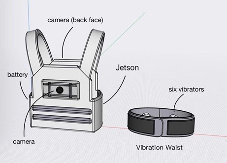
Figure 9. Final Design Prototype
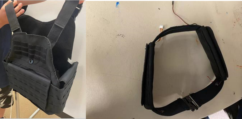
Figure 10. Final Product
7. Miscellaneous
7.1. Cost Analysis
The estimated manufacturing cost of our final product is almost 888 dollars. The MSRP should be 1099 dollars. We decided to build a long-term relationship with suppliers and plan to produce 5000 products per year, so we materials at a price slightly lower than the market wholesale price. See Tablefor detailed information.
Table 6. MSRP Analysis
MRSP Analysis (5000 pieces / year) | ||||
1. MATERIAL | Quantity | Cost | Total | |
NVIDIA Jetson TX2 development board | 5,000.0000 | $200.00 | $1,000,000.00 | |
Webcam | 10,000.0000 | $4.70 | $47,000.00 | |
256GB SD Card | 5,000.0000 | $30.00 | $150,000.00 | |
Bulletproof vest | 5,000.0000 | $25.00 | $125,000.00 | |
Vibration motor | 30,000.0000 | $1.35 | $40,500.00 | |
12V 7AH Lithium Battery | 5,000.0000 | $25.00 | $125,000.00 | |
Sports waist belts | 5,000.0000 | $10.00 | $50,000.00 | |
Indirect costs (35% of all material) | – | 35% | $538,125.00 | |
MATERIAL | – | – | $2,075,625.00 | |
2. LABOR | Set Up (# of Min) | Run (# of Min) | Cost / Hour | Total |
Assembly | 5 | 50,000.00 | $6.00 | $5,000.50 |
Sewing | 10 | 100,000.00 | $20.00 | $33,336.67 |
Machining | 5 | 50,000.00 | $10.00 | $8,334.17 |
Welding | 5 | 150,000.00 | $30.00 | $75,002.50 |
Labor | – | – | – | $121,673.83 |
3. OVERHEAD | 100% | $2,197,298.83 | ||
(ON MATERIAL & LABOR COSTS) | Subtotal | $4,394,597.67 | ||
25% Profit | 1.25 | |||
4. Price | $5,493,247.08 | |||
7.2. Time Line
The actual timeline is a little different between we planned before. We finished the GPS part and realized identifying objects and measuring their size before the spring break. However, we did not finish the trajectory prediction part [11]. There are several reasons. The first problem is that finally we did not use raspberry pi but Jetson TX2, which wastes us a lot of time completing transfer of all data, code and libraries. Meanwhile, due to our unfamiliarity with Jetson TX2, we spent a lot of time learning how to use it. After the spring break, we finally finished the task of trajectory prediction, and the real data were collected for testing. We did not finish the vibration part, but we can plot two lines from GPS and trajectory prediction on one figure and define whether they have the potential to have an intersection. The timeline figure (Fig. 11) is attached below.
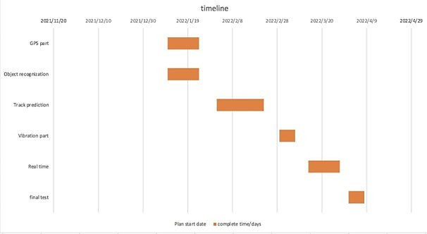
Figure 11. Last Semester Timeline Gantt Chart
7.3. Learning Plans and New Knowledge Acquired
We learnt about how to use Jetson TX2 to train some models. Meanwhile we successfully use GPS to get the latitude and longitude coordinates to get the users’ trajectory. We also learned how to capture continuous images from the video and export them into pixel values.
7.4. Codes and Standards
We will strictly abide by professional and business ethical standards and requirements. All actions will be in accordance with the provisions of the law and we will not steal the results of others [12]. The use of other people’s technical and theoretical knowledge clearly states its origin. Meanwhile, we strictly comply with product safety standards when making products to ensure the safe use of users.
8. Next Steps
Our project still has a lot of potential for improvement and development. Firstly, the functions that our products can do at present are not very comprehensive. There should be many ideas for the function of helping the visually impaired people to travel alone. So we can enrich the functionality of our products, build another assistive system to ensure the safety level. Secondly, our products do not use sensors for distance detection. Our team has also considered whether using lidar or other sensors can achieve better results. A better solution is that we can build a sensor system, provides a double-protection in case that vision not working accurately. Thirdly, our team also gave serious thought to the power supply problem. At present, our products can continue to work for about ten hours on a single charge and we can apply solar technology to extend the working duration. Otherwise, if we have more resources and time, we can overcome some technical problems that we have not solved yet, such as processing video automatically, letting the neural network match the identified object with the number and so on.
9. Conclusions
Our team has designed and manufactured a wearable device that can help users avoid obstacles in view of the difficulty of traveling alone for visually impaired people. We decided to use the vision system and GPS to predict the trajectory of the obstacle, and use the vibrator in different positions to help the user identify the direction of the obstacle for the purpose of obstacle avoidance. During the first semester, we clarified the direction of our subject, conducted market research, and understood the objective needs of visually impaired people. We designed and modeled our product and purchased the parts and materials we needed. In the second semester, we have a reasonable division of labor for the functions we want to accomplish. We have carried out research on vision systems, GPS and neural networks respectively. Finally, we carried out a series of data collection and functional tests and completed the construction of the finished product. This project is roughly completed, and it can predict the trajectory of humans and provide warnings via vibrators to users. But at present, our project still has some errors and deficiencies. The direct beneficiaries of our products are all visually impaired people. Relatively speaking, it’s able to help vision-impaired people decrease the risk of independently walking on the street.
References
[1]. Tim. “Object and Animal Recognition With Raspberry Pi and OpenCV.” core electronics, https://core-electronics.com.au/guides/object-identify-raspberry- pi/.15 April 2022.
[2]. Kuriakose, Bineeth, Raju Shrestha, and Frode Eika Sandnes. ”Tools and technologies for blind and visually impaired navigation support: a review.” IETE Technical Review (2020): 1- 16.
[3]. Real, Santiago, and Alvaro Araujo. ”Navigation systems for the blind and visually impaired: Past work, challenges, and open problems.” Sensors 19.15 (2019): 3404.
[4]. National Federation of the Blind. “Blindness Statistics”. National Federation of the Blind, https://nfb.org/resources/blindness-statistics 4 December 2021.
[5]. Strap Technologies. https://strap.tech/ . 4 December 2021.
[6]. Church, Andy. “This is Why Product Quality is Important for Consumer Brands (5 Reasons)”. Insight Quality Services, https://insight-quality.com/why- product-quality-is- important/ 3 September 2021.
[7]. Hattori, Masayuki, and Sumiyoshi Abe. ”Path probability of stochastic motion: A functional approach.” Physica A: Statistical Mechanics and its Applications 451 (2016): 198- 204.
[8]. Hesse, Constanze, et al. ”Pathways involved in human conscious vision contribute to obstacle-avoidance behaviour.” European Journal of Neuroscience 36.3 (2012): 2383-2390.
[9]. Tim. “Detect Speed with a Raspberry Pi, Camera and OpenCV.” core electronics, https://core-electronics.com.au/guides/detect-speed-raspberry-pi/ .15 April 2022.
[10]. EdjeElectronics, and ladyada, and davidbradway. “Tutorial to set up TensorFlow Object Detection API on the Raspberry Pi.” Github, https://github.com/EdjeElectronics/ TensorFlow- Object-Detection-on-the-Raspberry-Pi .20 April 2022.
[11]. Automaticaddison. “How to Read Input from a Push Button Switch on Raspberry Pi 3 Model B+.” Automatic Addison, https://automaticaddison.com/how- to-read-input-from-a- push-button-switch-on-raspberry-pi-3-model-b/ . 20 April 2022.
[12]. BOXENTRIQ, “https://www.boxentriq.com/code-breaking/pixel-values-extractor”, Pixel Values Extractor, 20 April 2022.
Cite this article
Chen,Y.;Zhan,Z. (2024). Clairvoyance: Vision-impaired friendly assistive mobile device. Applied and Computational Engineering,65,45-65.
Data availability
The datasets used and/or analyzed during the current study will be available from the authors upon reasonable request.
Disclaimer/Publisher's Note
The statements, opinions and data contained in all publications are solely those of the individual author(s) and contributor(s) and not of EWA Publishing and/or the editor(s). EWA Publishing and/or the editor(s) disclaim responsibility for any injury to people or property resulting from any ideas, methods, instructions or products referred to in the content.
About volume
Volume title: Proceedings of Urban Intelligence: Machine Learning in Smart City Solutions - CONFSEML 2024
© 2024 by the author(s). Licensee EWA Publishing, Oxford, UK. This article is an open access article distributed under the terms and
conditions of the Creative Commons Attribution (CC BY) license. Authors who
publish this series agree to the following terms:
1. Authors retain copyright and grant the series right of first publication with the work simultaneously licensed under a Creative Commons
Attribution License that allows others to share the work with an acknowledgment of the work's authorship and initial publication in this
series.
2. Authors are able to enter into separate, additional contractual arrangements for the non-exclusive distribution of the series's published
version of the work (e.g., post it to an institutional repository or publish it in a book), with an acknowledgment of its initial
publication in this series.
3. Authors are permitted and encouraged to post their work online (e.g., in institutional repositories or on their website) prior to and
during the submission process, as it can lead to productive exchanges, as well as earlier and greater citation of published work (See
Open access policy for details).
References
[1]. Tim. “Object and Animal Recognition With Raspberry Pi and OpenCV.” core electronics, https://core-electronics.com.au/guides/object-identify-raspberry- pi/.15 April 2022.
[2]. Kuriakose, Bineeth, Raju Shrestha, and Frode Eika Sandnes. ”Tools and technologies for blind and visually impaired navigation support: a review.” IETE Technical Review (2020): 1- 16.
[3]. Real, Santiago, and Alvaro Araujo. ”Navigation systems for the blind and visually impaired: Past work, challenges, and open problems.” Sensors 19.15 (2019): 3404.
[4]. National Federation of the Blind. “Blindness Statistics”. National Federation of the Blind, https://nfb.org/resources/blindness-statistics 4 December 2021.
[5]. Strap Technologies. https://strap.tech/ . 4 December 2021.
[6]. Church, Andy. “This is Why Product Quality is Important for Consumer Brands (5 Reasons)”. Insight Quality Services, https://insight-quality.com/why- product-quality-is- important/ 3 September 2021.
[7]. Hattori, Masayuki, and Sumiyoshi Abe. ”Path probability of stochastic motion: A functional approach.” Physica A: Statistical Mechanics and its Applications 451 (2016): 198- 204.
[8]. Hesse, Constanze, et al. ”Pathways involved in human conscious vision contribute to obstacle-avoidance behaviour.” European Journal of Neuroscience 36.3 (2012): 2383-2390.
[9]. Tim. “Detect Speed with a Raspberry Pi, Camera and OpenCV.” core electronics, https://core-electronics.com.au/guides/detect-speed-raspberry-pi/ .15 April 2022.
[10]. EdjeElectronics, and ladyada, and davidbradway. “Tutorial to set up TensorFlow Object Detection API on the Raspberry Pi.” Github, https://github.com/EdjeElectronics/ TensorFlow- Object-Detection-on-the-Raspberry-Pi .20 April 2022.
[11]. Automaticaddison. “How to Read Input from a Push Button Switch on Raspberry Pi 3 Model B+.” Automatic Addison, https://automaticaddison.com/how- to-read-input-from-a- push-button-switch-on-raspberry-pi-3-model-b/ . 20 April 2022.
[12]. BOXENTRIQ, “https://www.boxentriq.com/code-breaking/pixel-values-extractor”, Pixel Values Extractor, 20 April 2022.