


SLAM technology, Unmanned inspection robots, Autonomous navigation, LiDAR integration, ORB-SLAM3.
1. Introduction
With the continuous advancement of technology, the wave of intelligence and automation is sweeping across various industries. In this era, unmanned inspection robots have emerged as the new favorite in the field of inspection, thanks to their efficient, precise, and safe characteristics. [1] The advent of unmanned inspection robots has brought revolutionary changes to inspection work. Leveraging their efficient, precise, and safe features, they play a significant role in various sectors such as electricity, petrochemicals, and manufacturing. Within the technical system of unmanned inspection robots, positioning and navigation technology are the key to achieving autonomous operation. Simultaneous Localization and Mapping (SLAM) technology, in particular, is an important innovation in the positioning and navigation technology of unmanned inspection robots. Today, let us unveil the mysterious veil of SLAM [2] technology and explore its applications and advantages in unmanned inspection robots. In this article, we delve into the intricacies of SLAM technology, its integration with artificial intelligence, and how it facilitates robotic navigation and localization in environments where the terrain is unknown. We will discuss its role in enabling robots to create maps of their surroundings in real-time, while simultaneously determining their own position within those maps. Through this exploration, we aim to shed light on the [3] transformative potential of integrating artificial intelligence with SLAM technology, paving the way for safer, more efficient, and more autonomous robotic inspection systems across industries.
2. Related work
2.1. Simultaneous Localization And Mapping(SLAM)
SLAM, short for Simultaneous Localization And Mapping, was first proposed by Hugh Durrant-Whyte and John J.Leonard in 1988. SLAM is more of a concept than an algorithm. It is defined to solve the problem of "starting from an unknown location in an unknown environment, the robot locates its own position and posture through repeated observed map features (such as corners, columns, etc.) in the process of movement, and then incrementally builds a map according to its own position. To achieve simultaneous positioning and map construction of the purpose of the "problem method." The principle of SLAM technology is to use cameras, [3-4] liDAR or sensors such as vision sensors, inertial measurement units, to collect environmental information, and then use algorithms to fuse this information to determine the location of the robot in an unknown environment and build a map of the environment. Therefore, the SLAM problem can be formalized as a Bayesian filtering problem, where the robot's state and map features are modeled as probability distributions. Common SLAM algorithms include methods based on [5] Extended Kalman filter (EKF-SLAM), particle filter, and graph optimization. These algorithms use different mathematical tools to solve SLAM problems, the specific choice depends on the application scenario and the availability of computing resources. SLAM technology is critical to the ability of a robot or other agent to move and interact, because it represents the basis for that ability: knowing where it is, knowing what its surroundings are like, and then knowing how to act autonomously next.
The entire visual SLAM process consists of the following steps:
1. Read the sensor information. The main purpose of visual SLAM is to read and preprocess camera image information.
2. Visual Odometry (VO). The task of the visual odometer is to estimate the motion of the camera between adjacent map images and what the local map looks like. [6] VO is also known as the preceding segment.
3. Back-end Optimization. The back end receives the camera position and attitude measured by the visual odometer at different times and the information of the loop detection, and optimizes them to get a globally consistent trajectory and map. Since it is connected after VO, it is also called the back end.
4. Check the Loop Closing. Loop detection determines whether the robot has reached the previous position. If a loop is detected, it provides the information to the back end for processing.
5. Mapping. Based on the estimated trajectory, he builds a map corresponding to the mission requirements.
2.2. LIDAR
Implementing SLAM requires two types of techniques. One type of technology is sensor signal processing (including front-end processing), which depends largely on the sensor used. Another type of technology is pose optimization (including back-end processing), which is sensor-independent. Therefore, although SLAM is an algorithm technology, the basis for the application of SLAM is a sensor with excellent performance (LiDAR or image sensor). Depending on the sensor choice, there are currently two schools of technology: visual V-SLAM and liDAR SLAM [7]. Multi-line LiDAR can acquire multiple scanning lines at the same time, which improves the efficiency and accuracy of data acquisition. [8]2D LiDAR and [9]3D LiDAR: 2D LiDAR can only acquire two-dimensional information about the environment, such as distance and Angle, and is commonly used for plane navigation and obstacle avoidance. 3D Lidar can obtain three-dimensional information about the environment, including height, for building three-dimensional maps and conducting three-dimensional navigation.
The multi-line LiDAR 3D SLAM technology can theoretically build a 3D point cloud map of a million square meters of large scenes, and the perceived environmental information features are rich, and the positioning and matching are stable, which is suitable for most scenes. Why theoretical? Because the premise is that the sensor is good enough to generate a dense point cloud.
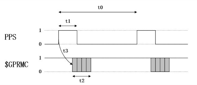
Figure 1. Transmission architecture of Lidar implemented by sdk protocol
Therefore, in the Figure 1,in the realization of robot self-positioning and navigation, according to the sensor configuration given by the laser God intelligence, the 16-line 3D [10]Lidar uses the leading core signal processing ASIC chip and advanced multiple echo detection technology and data calibration technology, and the point cloud output can reach 320,000 points/second, which is the leading point cloud performance in the entire industry. With this level of composition, the outdoor measurement accuracy can reach ±3cm and the indoor measurement accuracy can reach ±2cm.
2.3. Robot autonomous localization
SLAM technology can realize autonomous localization and navigation of inspection robots by integrating sensor data and map information. The robot uses lidar, vision sensors and other devices to collect data to estimate its position and update the map in real time. The robot can accurately navigate in the unknown environment and complete the inspection task. In the visual navigation and positioning system for autonomous positioning of robots, the navigation method of installing vehicle cameras in robots based on local vision is widely used at home and abroad. In this navigation mode, control equipment and sensing devices are loaded on the robot body, and [11] high-level decisions such as image recognition and path planning are completed by the on-board control computer.
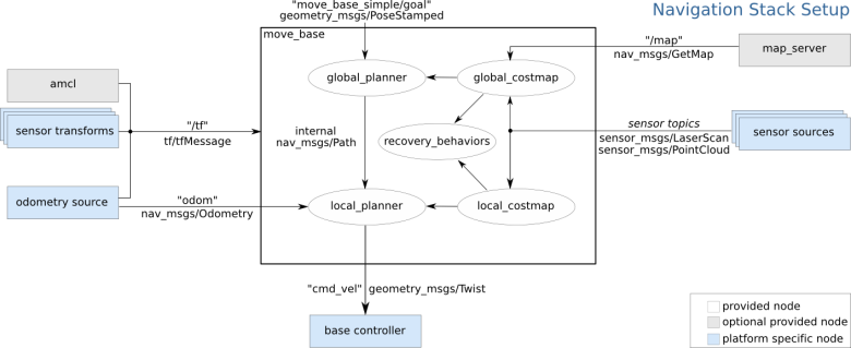
Figure 2. Multi-modal path architecture of robot autonomous navigation and positioning
In Figure 2, move_base function package realizes optimal path planning in robot navigation, and amcl realizes robot positioning in two-dimensional map. In order to realize the robot's global optimal path planning and real-time obstacle avoidance path planning, move_base needs to subscribe to depth sensor information (sensor_msgs/LaserScan or sensor_msgs/PointCloud) and Odometry information published by the robot, At the same time, the complete TF coordinate transformation is also an important basis for path planning. The final output of the navigation frame is the control robot's velocity instruction (geometry_msgs/Twist) [12], which requires the robot control node to have the ability to analyze the center line velocity and angular velocity of the control instruction, and control the robot to complete the corresponding motion.
Through SLAM technology, the robot can detect and avoid obstacles more accurately, thus improving the safety and efficiency of inspection.SLAM technology associates the robot's perception data with map information through data association technology to realize the perception and understanding of the environment. The robot can perform positioning and attitude estimation by matching sensor data with map features. This allows the robot to accurately sense changes in the environment and provide reliable navigation and inspection data. SLAM technology is relevant here because it allows the robot to update the map based on real-time perception data and combine the perception data with map information through data association technology. Through SLAM technology, robots can better understand the environment and improve the accuracy and reliability of navigation and inspection.
3. Methodology
Completing complex tasks in large-scale complex scenes is a challenging task for robots, especially the need to build dense point cloud maps to provide more effective information, and the need for efficient composition. However, the traditional multi-robot SLAM algorithm often has some problems such as high computational complexity, low efficiency and poor real-time performance when constructing global maps. To address these challenges, a multi-robot collaborative map building algorithm based on ORB-SLAM3is proposed. Through the collaborative method, the algorithm significantly improves the efficiency of map construction, while maintaining high real-time and positioning accuracy, showing a good development prospect.
3.1. ORB-SLAM3
Visual SLAM is a SLAM system based on visual sensors. Compared with laser sensors, visual sensors have the advantages of low cost, preserving environmental semantic information, and can be combined with deep learning. ORB-SLAM series algorithms are the most widely concerned and applied algorithms in visual SLAM. The ORB-SLAM3 is a visual, visual + INS, hybrid mapping SLAM system that can operate with pinhole or fisheye models on monocular, binocular, and RGB-D cameras. In large/small scenes, indoor/outdoor, ORB-SLAM3 can be robust real-time operation, is widely used in commercial products.Multiple submap systems greatly improve system recall, and ORBSLAM3 is more robust when visual information is lacking or even lost. When the target is lost, a submap is rebuilt and merged with the previous inactive map during the loop closing process. Therefore, ORB-SLAM3 is the first system that can reuse the information obtained by all the algorithms in the history, which means that previous co-view keyframes can also be used together (both the co-view keyframes of active and inactive maps in the Atlas).
In order to obtain a higher recall rate, for each new active key frame, the system queries several similar key frames in Atlas in the DBoW2 database. In order to achieve 100% accuracy, each candidate keyframe is geometrically validated in several steps. The basic operation of all geometry validation steps is to check whether there are ORB feature points in the image window whose descriptors match the ORB descriptors of the mapping points, and to use the Hamming distance threshold between them.
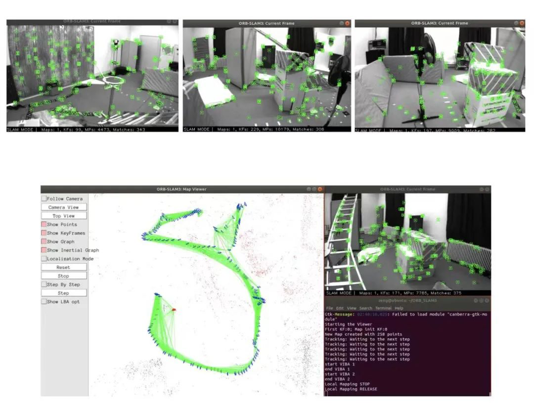
Figure 4. Procedure diagram for constructing and locating the ORB-SLAM3 multimodal map
3.2. Robotic autonomous positioning results
In pure vision, the multi-map system adds robustness to fast motion by creating a new map when tracking is lost, which is later merged with the global map. This can be seen in the sequences V103 monocular and V203 Binocular 11, ORB-SLAM2 cannot solve these problems, and our system successfully solves these problems in most implementations. Precisely because of its faster feature initialization, binocular vision is more robust than monocular vision and has the added advantage of estimating true proportions. However, a huge leap in robustness was achieved with our novel Visual Inertial SLAM system, in both monocular and binocular configurations. Binocular inertial systems have a very small advantage, especially in the most challenging V203 sequences. We can conclude that inertial integration not only improves accuracy and reduces median ATE error compared to purely visual solutions, but also gives the system excellent robustness and more stable performance.
3.3. Result discussion
Therefore, an open-source library for visual-inertial and multi-session SLAM, supporting monocular, stereo, RGB-D, pinhole, and fisheye cameras, has been developed. Apart from the integrated libraries themselves, our primary contributions include rapid and accurate initialization techniques for inertial measurement units and multi-session map merging functionalities. These functionalities rely on a novel position recognition technique with improved recall rates, rendering ORB-SLAM3 highly suitable for long-term and large-scale SLAM applications.
The experimental results demonstrate that ORB-SLAM3 is the first system capable of effectively utilizing short-term, medium-term, long-term, and multi-map data associations in visual and visual-inertial systems, achieving precision levels beyond what existing systems can achieve. On the other hand, matching feature descriptors successfully addresses long-term multi-map data associations but seems less robust than using Lucas-Kanade tracking.
4. Conclusion
SLAM has been a hot research topic in the field of intelligent vehicles for the past three decades. The first principle study of this method was initially focused on the autonomous control of mobile robots. SLAM applications have been used for a wide range of topics such as augmented reality (AR)visualization, computer vision modeling, and self-driving cars. In recent years, SLAM has been used as an intelligent technology for building 3D maps of environments using sensor fusion algorithms. In robotics, map building in SLAM usually refers to building a map that is geometrically consistent with the environment. This method has the largest redundancy of information, which is a great challenge for data storage. At the same time, it takes a lot of trouble for robots to extract useful data from it, so direct representation method is rarely used in practical applications.
In conclusion, we have introduced the pivotal role of SLAM technology in the advancement of robotic inspection systems. Leveraging SLAM's capabilities, robots can navigate, localize, and create maps of unknown environments autonomously. We have discussed the integration of SLAM with LiDAR technology, enabling precise environment mapping crucial for obstacle avoidance. Additionally, we presented a collaborative mapping algorithm based on ORB-SLAM3, enhancing map construction efficiency and real-time performance. Our findings demonstrate the transformative potential of SLAM technology, promising safer, more efficient, and more autonomous robotic inspection systems across industries. Through continued research and development, SLAM technology is poised to revolutionize robotic applications, driving further advancements in automation and intelligence.
References
[1]. Grisetti, Giorgio, et al. "A tutorial on graph-based SLAM." IEEE Intelligent Transportation Systems Magazine 2.4 (2010): 31-43.
[2]. Chong, T. J., et al. "Sensor technologies and simultaneous localization and mapping (SLAM)." Procedia Computer Science 76 (2015): 174-179.
[3]. Taketomi, Takafumi, Hideaki Uchiyama, and Sei Ikeda. "Visual SLAM algorithms: A survey from 2010 to 2016." IPSJ transactions on computer vision and applications 9 (2017): 1-11.
[4]. Kümmerle, Rainer, et al. "On measuring the accuracy of SLAM algorithms." Autonomous Robots 27 (2009): 387-407.
[5]. Mur-Artal, R., Montiel, J. M. M., & Tardos, J. D. (2015). ORB-SLAM: a versatile and accurate monocular SLAM system. IEEE transactions on robotics, 31(5), 1147-1163.
[6]. Wu, Y., Jin, Z., Shi, C., Liang, P., & Zhan, T. (2024). Research on the Application of Deep Learning-based BERT Model in Sentiment Analysis. arXiv preprint arXiv:2403.08217.
[7]. Ball, T., & Rajamani, S. K. (2000). The SLAM toolkit. In Proceedings of CAV’2001 (13th Conference on Computer Aided Verification) (Vol. 2102, pp. 260-264).
[8]. Forster, C., Lynen, S., Kneip, L., & Scaramuzza, D. (2013, November). Collaborative monocular slam with multiple micro aerial vehicles. In 2013 IEEE/RSJ International Conference on Intelligent Robots and Systems (pp. 3962-3970). IEEE.
[9]. Shi, C., Liang, P., Wu, Y., Zhan, T., & Jin, Z. (2024). Maximizing User Experience with LLMOps-Driven Personalized Recommendation Systems. arXiv preprint arXiv:2404.00903.
[10]. Huang, Zengyi, et al. "Application of Machine Learning-Based K-Means Clustering for Financial Fraud Detection." Academic Journal of Science and Technology 10.1 (2024): 33-39.
[11]. Haowei, M. A., et al. "Employing Sisko non-Newtonian model to investigate the thermal behavior of blood flow in a stenosis artery: Effects of heat flux, different severities of stenosis, and different radii of the artery." Alexandria Engineering Journal 68 (2023): 291-300.
[12]. Zou, D., & Tan, P. (2012). Coslam: Collaborative visual slam in dynamic environments. IEEE transactions on pattern analysis and machine intelligence, 35(2), 354-366.
Cite this article
Fan,C.;Li,Z.;Ding,W.;Zhou,H.;Qian,K. (2024). Integrating artificial intelligence with SLAM technology for robotic navigation and localization in unknown environments. Applied and Computational Engineering,77,245-250.
Data availability
The datasets used and/or analyzed during the current study will be available from the authors upon reasonable request.
Disclaimer/Publisher's Note
The statements, opinions and data contained in all publications are solely those of the individual author(s) and contributor(s) and not of EWA Publishing and/or the editor(s). EWA Publishing and/or the editor(s) disclaim responsibility for any injury to people or property resulting from any ideas, methods, instructions or products referred to in the content.
About volume
Volume title: Proceedings of the 2nd International Conference on Software Engineering and Machine Learning
© 2024 by the author(s). Licensee EWA Publishing, Oxford, UK. This article is an open access article distributed under the terms and
conditions of the Creative Commons Attribution (CC BY) license. Authors who
publish this series agree to the following terms:
1. Authors retain copyright and grant the series right of first publication with the work simultaneously licensed under a Creative Commons
Attribution License that allows others to share the work with an acknowledgment of the work's authorship and initial publication in this
series.
2. Authors are able to enter into separate, additional contractual arrangements for the non-exclusive distribution of the series's published
version of the work (e.g., post it to an institutional repository or publish it in a book), with an acknowledgment of its initial
publication in this series.
3. Authors are permitted and encouraged to post their work online (e.g., in institutional repositories or on their website) prior to and
during the submission process, as it can lead to productive exchanges, as well as earlier and greater citation of published work (See
Open access policy for details).
References
[1]. Grisetti, Giorgio, et al. "A tutorial on graph-based SLAM." IEEE Intelligent Transportation Systems Magazine 2.4 (2010): 31-43.
[2]. Chong, T. J., et al. "Sensor technologies and simultaneous localization and mapping (SLAM)." Procedia Computer Science 76 (2015): 174-179.
[3]. Taketomi, Takafumi, Hideaki Uchiyama, and Sei Ikeda. "Visual SLAM algorithms: A survey from 2010 to 2016." IPSJ transactions on computer vision and applications 9 (2017): 1-11.
[4]. Kümmerle, Rainer, et al. "On measuring the accuracy of SLAM algorithms." Autonomous Robots 27 (2009): 387-407.
[5]. Mur-Artal, R., Montiel, J. M. M., & Tardos, J. D. (2015). ORB-SLAM: a versatile and accurate monocular SLAM system. IEEE transactions on robotics, 31(5), 1147-1163.
[6]. Wu, Y., Jin, Z., Shi, C., Liang, P., & Zhan, T. (2024). Research on the Application of Deep Learning-based BERT Model in Sentiment Analysis. arXiv preprint arXiv:2403.08217.
[7]. Ball, T., & Rajamani, S. K. (2000). The SLAM toolkit. In Proceedings of CAV’2001 (13th Conference on Computer Aided Verification) (Vol. 2102, pp. 260-264).
[8]. Forster, C., Lynen, S., Kneip, L., & Scaramuzza, D. (2013, November). Collaborative monocular slam with multiple micro aerial vehicles. In 2013 IEEE/RSJ International Conference on Intelligent Robots and Systems (pp. 3962-3970). IEEE.
[9]. Shi, C., Liang, P., Wu, Y., Zhan, T., & Jin, Z. (2024). Maximizing User Experience with LLMOps-Driven Personalized Recommendation Systems. arXiv preprint arXiv:2404.00903.
[10]. Huang, Zengyi, et al. "Application of Machine Learning-Based K-Means Clustering for Financial Fraud Detection." Academic Journal of Science and Technology 10.1 (2024): 33-39.
[11]. Haowei, M. A., et al. "Employing Sisko non-Newtonian model to investigate the thermal behavior of blood flow in a stenosis artery: Effects of heat flux, different severities of stenosis, and different radii of the artery." Alexandria Engineering Journal 68 (2023): 291-300.
[12]. Zou, D., & Tan, P. (2012). Coslam: Collaborative visual slam in dynamic environments. IEEE transactions on pattern analysis and machine intelligence, 35(2), 354-366.