


1. Introduction
While the potential shortage of the workforce will be more likely an unignorable issue for the most traditional manufacturers because of the factors from different aspects, no matter the concerns regarding the working intensity, the abruption of the talent storage for the realm of traditional manufacturing, or the siphon of informative industries, try to reduce the workload of the involved processes by partially or fully automating the working steps has become the most valuable choice if it’s not the only choice for seeking a smoother transition to meet the requirements of technological upgrades, in comparison with shifting the plant and adapting a new supply system. Even the urgency of the automation can be sensed by every traditional manufacturer at a specific moment, it’s still not an easy step for most of them to invest the automation, especially for those manufacturers that their products are all customized or non-standardized, not only the advantage of automation on manufacturing efficiency will be squeezed, the weakness of its robustness will be amplified, and the highly cost will be questioned by the high degree of the operational complexity [1]. Precision Casting is also a participant of manufacturing the non-standard parts; however, benefitted from its recognizable patterns of the manufacturing processes, most of its involved processes already have the corresponding automation solutions, such as the processes of Tree Assembly, Shell Making, and Surface Finishing, even though the automation solution for each process requires an expensive price.
This article will try to explore a general concept for automating the process with the heaviest workload among all the involved processes of Precision Casting– the metal pouring process. Instead of fully automating the entire metal pouring process, a human-robots collaborative mode will be proposed for integrating into the automation, along with the implementation of matured technologies (e.g. 3D Scanning and Visual Identification) and the utilization of the Computer Science algorithms (e.g. Object Bounding, Greedy Strategic, Last-In-First-Out). By simplifying the specific working steps with the involvement of human intervention and shifting the potential complexities to the corresponding algorithms, the introduced method of automation will repetitively emphasize the priority of maximizing the robustness and the flexibility of the automation when dealing with the various types of pouring targets.
2. Workflow and analysis for the metal pouring process
The workflow for the metal pouring process is consisted of Mould Grasp, Placement, Retrieval from Pre-heating Oven and Pouring, and Cycle-finish Placement, which is shown in figure 1. Each stage will be exposited as the working sequence with the explanation of how the operations are expected to be done by robotics or adaptively processed by the applied computer algorithms.
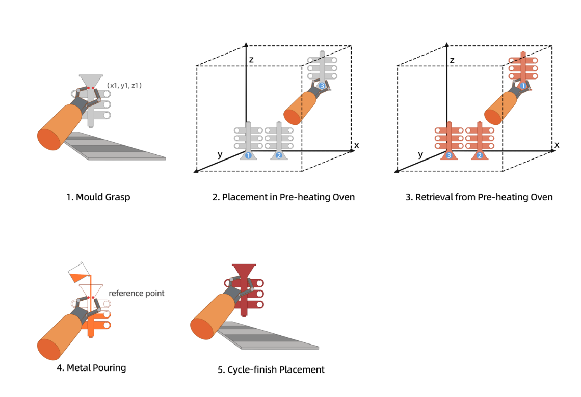
Figure 1. Workflow Diagram (Photo/Picture credit: Original)
2.1. World Frame and User Frames
The automation solution on this process requires a giant world frame for the involved robotic arms; however, directly constructing a complete world frame while also requiring an ideal accuracy on robots’ operation will incredibly lift the pressure on coordinate system calibration and be lack of capability to the potential changing layout of the work area [2]. Construct a world frame that is mainly consisted of the moving routes, separate the other involved frames for working operations into different modules and trigger the needed user frames when the robotic arms arriving the specified location or reference point has become a method to distribute the processing pressure to the involved stages correspondingly, since the user frames can be relatively established at any position within the working space of the robot mentioned by Cheng in Robot Manipulators [3].
The constructed user frames can be classified into the 3 working areas, i.e. the area of Mould Grasp and Finish Placement, the area of Placement and Retrieval from Pre-heating Oven, and the area of Pouring. The separated scenarios additionally ask the smooth collaboration between each two stages from the workflow in comparison with the single integrated world frame, but this offers more possibilities on the profound upgrades on each defined user frame without affecting the overall system, a higher efficiency can also be realized by tailoring the robots’ performance according to the required operational accuracies from different stages.
2.2. Manual Preparation
As a necessity, some initial preparations of the other stages also require manual collaboration for the construction of user frames or the designation of reference points.
These manual preparations are categorized into the preparations on invariables and variables respectively. The invariable here are defined as the element from the preparations remaining unchanged and repetitively utilizable until the working environment changes, while the variables are requiring more frequent manual interventions because of the diversity of pouring targets under this context.
2.2.1. Invariables
Except the world frame construction and the fixed coordinates defined from different user frames, such as the specified location for the cycle-finish placement, the relevant preparation on pre-heating oven should be deliberated.
The inner space of the pre-heating oven is required to be mirrored by 3D scanning, form a spatial coordinate serving for the robots’ movement and operation, meanwhile, the coordinate is expected to be convertible to 3 dimensional binary matrices for reducing the computation complexity and ease the scheduling of mould placement with greedy strategic algorithm.
Noticeably, both the process of 3D scanning and the construction of spatial coordinates for robotic movement can be simultaneously conducted during the manually guided movement if the robotic arm is available to be equipped with the 3D scanner and is integrated with human-robot collaboration control algorithms that has been introduced in Safe and intuitive manual guidance of a robot manipulator using adaptive admittance control towards robot agility [4].
2.2.2. Variables
The preparations for the stages of Mould Grasp and Pouring are defined as variables, since these stages constantly requires a certain manual intervention for more accurately measuring and effectively dealing with the potential changing elements brought by the different pouring targets.
Once a mould is planned into the pouring process, the 3D models of the pouring target need to be constructed by the 3D scanner. As long as the 3D model been constructed, the corresponding grasp position is expected to be determined by passing the model into the trained algorithms of grasp detection that have been mentioned and summarized in Overview of robotic grasp detection from 2D to 3D [5], and store the grasp position in the database for avoiding the repetitive detection of the same type moulds.
Since the different pouring targets may also have the different designs regarding the sprue location and sizes, manual intervention can more efficiently to guarantee an accurate pouring point for the robotic arms if no additional cooperative cameras are intended to be equipped around pouring area because at least one staff is always required to present for adding microelements, decide the pouring operation and supervise the real-time status during the process.
The determination of pouring position can be done and recorded just after the grasp detection and before placing the grasped mould into the oven, involve human-robot collaboration can also drastically increase the efficiency for this process [4].
A further considerable give-and-take on this process is whether all the same type moulds should still perform the movement of pouring position determination before placing into the pre-heating oven, or directly retrieve the coordinates of pouring point which was recorded from the first mould of the corresponding type during the pouring stage. Repetitively performing the trajectory and operations from grasp moulds to arrive specified pouring point then place the mould into pre-heating oven can form a consistent movement and operation sequence that is just reversed to the sequence should be performed during the pouring stage. The benefits brought by reverse execution and the logics behind are demonstrated by Laursen, Ellekilde and Schultz with the study cases of robotic assembly [6]. In this solution, this approach no longer requires additional programing for complementing the robots’ trajectories and operations from the pre-heating oven to the specified pouring point, but the processing time of placement in pre-heating oven and attrition rate of the robotic joints will be predicatively prolonged and increased.
2.3. Mould Grasp
At the stage of mould grasp, the same type moulds that have been recorded with the corresponded 3D model can be delivered to the robots through the conveyor one at a time, but place the moulds in the same direction towards the robots if the mould structure is not symmetrical will be more likely to increase the efficiency of the grasp operation and ensure the validity for the repetitive usage of the stored detections.
Regarding switching the grasp position for the mould that its type is different with the previous one, Approach 1. pre-defining a grasp number and sequence for each type of the mould and switch the grasp coordinates as the specified sequence once the grasp number for the mould is reached; Approach 2. or equipping cameras for visual identification and automatically retrieving the grasp coordinates according to the matching results; both can save the manual intervention during the process of deliver-to-grasp.
Even if applying Approach 2, the behaviour of pre-defining grasp number and sequence is still encouraged, because it enables the pre-scheduling of the placement in pre-heating oven, releases the tension for the algorithm performance on real-time processing, and leaves more space for the placement optimization.
2.4. Placement in Pre-heating Oven
Following the stage of mould grasp and pouring point determination if it’s applied, the stage of placement in pre-heating oven will be extended starting from the common behaviours of placing the moulds, to the explanation of the techniques and algorithms that need to be involved by the solution, i.e. Object Bounding and Greedy Strategy.
2.4.1. Placing Behaviours
It is valuable to summarize the common placement behaviours to form an operational norm and functioning as a reference for the placement processing by robots. There, 3 behaviours of placement will be briefly introduced and considered into the solution.
The moulds that been placed into the pre-heating oven in a same batch will be pre-heated with the same configuration, generally means those moulds are going to be poured with the same materials even they’re the different types. Regardless, different post-pouring actions may require to be applied on those moulds for a stable process of solidification; hence, the same type moulds will still be placed next to each other instead of mixing the placement of different types for seeking a maximized space utilization.
The sprue of the moulds should be downwardly placed to prevent the dust enter the cavity of moulds during the process of pre-heating and causes surface defects. During the entire pouring process, the involved robots will turn the mould sprue upside down for at least twice if sprue is strictly required downward placement; meanwhile, the coordinates transformation for changing the grasp direction should also be considered between each connected stage. For seeking an operation sequence to be completely invertible, the placement direction of the sprue should be upwardly placed on the conveyor initially to make sure the sprue of the poured mould is also upward. In other words, the initial placement posture decides the final placement posture if operation sequence will be fully inverted.
For increasing the pre-heating number of moulds at once, the moulds may be stacked 2 or 3 moulds high depending on the height of the inner volume of the pre-heating oven if the mould shape is stable and supportive, and the heating effect will not be influenced by the large occupation rate of the space. In this solution, the number of stacks should be manually specified and inputted into the placement algorithm for setting the constraints and generating the corresponding placement schedule.
2.4.2. Object Bounding
Due to the various designs and shapes of the moulds, directly input these shapes into the computation of the placement scheduling will bring unnecessary complexity to both the relevant programming and the profound movement of robots when grasping a mould.
In this solution, all the moulds will be object bounded using the simplest AABBs approach by only retrieving the maximum length from different coordinate directions and form a cube. The simplicity of this approach not only intuitively reduces the complexity of the grasping movement of robots, but also converts the disadvantage of this approach on spatial utilization to become another guarantee for preventing the potential collision during the robotic grasp movement. The difference between the AABBs and OBBs on 3D objects have already been presented in 3D model-based scan planning for space frame structures considering site conditions under the context of site constructions [7]. The flowchart for the algorithm of AABBs when applying on the moulds can be illustrated as in figure 2.
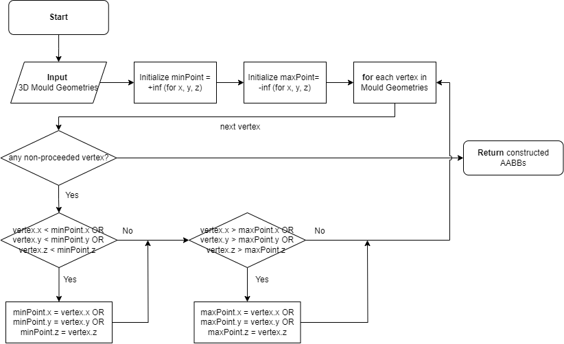
Figure 2. AABBs Object Bounding Flowchart (Photo/Picture credit: Original)
2.4.3. Greedy Strategy
Greedy strategy has been commonly applied on the Computer Science issues for pathfinding, activity selection and scheduling with its simplicity of the applied algorithm, efficiency brought by the discovery of only local optimal solution, and the adaptability to the specified constraints [8, 9].
At this stage, greedy strategy can offer ideal response time and reasonable occupancy, while also assure the multi-constraints like grouping placement, initiating placement from the inner side, spacing moulds to prevent collisions, and maintaining adequate clearance for robotic grasp operations.
The general part of the placement algorithm with the considerations of constraints can be extended by the flowchart as in figure 3.
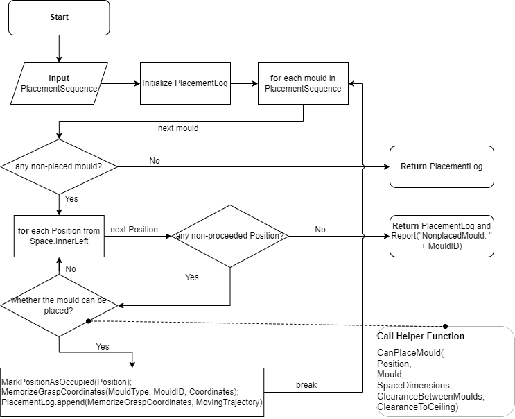
Figure 3. Greedy Strategic Placement Flowchart (Photo/Picture credit: Original)
The involved helper function CanPlaceMould is responsible for the heaviest tasks of both checking the compliance of constraints and determining the space availability; however, this helper function will not be further expanded in detail even there is still a lot of strategies can be explored and deployed for increasing the overall computational complexity, such as discretize the space of pre-heating oven or keep recording and tracking the space utilization status.
During the process of placement, the grasp coordinates and moving trajectory of each mould is memorized and merged to the history of robotic operation sequence for reversely retrieving the pre-heated moulds at the pouring stage.
2.5. Retrieval from Pre-heating Oven, Pouring and Cycle-finish Placement
With the recorded operation sequence from previous stages, when processing these stages, the recorded sequence will be reversed as the principle of LIFO (Last In First Out) to realize all the automations of retrieval from pre-heating oven, reaching the specified pouring point, and placing the poured mould to the conveyor [8].
For ensuring the flexibility and efficiency of the data invoking, the method of LIFO instead of the strict data structure of stack will be applied; hence, no stack will be additionally created for the reverse execution, instead, the operations will be directly processing from the tail of the recorded operation sequence.
The relevant flowchart for the algorithm of realizing reverse retrieval, reaching to pouring point and final placement can be illustrated as in figure 4.
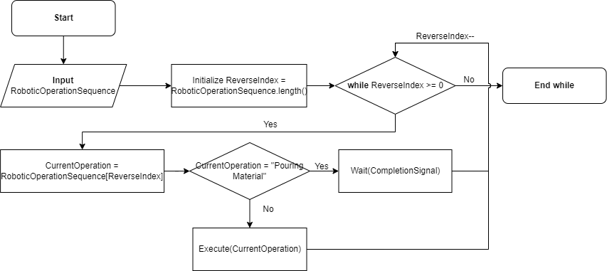
Figure 4. Reverse Operation Sequence Flowchart (Photo/Picture credit: Original)
The operation – “Pouring Material” within the algorithm is an abstract pause command for waiting the process of pouring material, the abstract command should be placed right after the pouring point determination and before the movement for placing the mould into the pre-heating oven.
The completion signal is proposed to be manually sent if the pouring oven is controlled by supervisors, but the signal sending is surely automatable if combined with visual identification or some simple trigger mechanisms such as – 1. Active Trigger: the measurement on robotic lifting weight, or 2. Passive Trigger: the measurement of the weight difference, and the additional variables and pre-specification for the pouring weight of each mould will become necessary.
Regarding the reverse execution of robotic operations, it is critical to assure that the robotic commands follow the one-to-one pattern mentioned in to avoid the reversibility being broken by the commands that work as implicit conditions and perform the operations in the unintended ways [6].
2.6. Challenges analysis
The compatibilities between the non-uniform operating systems and the different data formats have been discovered as the most obvious issue that need to be confronted with when implementing an automation consisted of the multiple facilities from the different platforms, especially when those operating platforms are not constructed based on the same underlying infrastructure; moreover, the facilities from the different platforms also have the different freedom of interactions, which causes the results of certain steps cannot be solely processed in the most efficient way. The compatibility issues have been addressed and categorized into the different levels by Vyatkin, here, this kind of status also restricts that the actual solution can only be designed and generated from the compromise, within the intersection of the functions from different platforms [10].
3. Conclusion
This article intends to present a robust and easy-operational automation method on the metal pouring process of Precision Casting to deal with the various types of pouring targets, the method keeps trying to reduce the unnecessary complexities from all the involved steps to save the cost and increase its overall acceptability.
Beginning with the construction of the world frame and user frames, establishing multiple user frames has been proposed to increase the capability to the potential change of the working layout. The manual preparations are then introduced as the categories of invariables and variables, including the discussion regarding the fundamental topics like – 3D model construction of the inner space of the pre-heating oven, mould modelling, identifications of grasp and pouring positions. Two different approaches – pre-defining grasp numbers, and adaptively selecting grasp coordinates by visual identification are further expanded in the section of Mould Grasp, meanwhile, the idea of reversing operation sequence of robotics by utilizing the symmetrical characteristics of the working steps is imported. Transfer the theme to the section of placement in pre-heating oven, the discussion starts from the summarization of placing behaviours, then dive into the employed techniques – AABBs Object Bounding and Greedy Strategy, illustrate the purposes and the logics behind the optimization by walking through the corresponding flow charts of the algorithms. After that, all the left working steps – retrieval from pre-heating oven, pouring, and cycle-finish placement will be reversely processed according to the principles of LIFO (Last-In-First-Out), while the step of pouring requires the insertion of the waiting signal between the adjacent processes to hold a duration of pouring, it also brings the considerations regarding the difference between the signal responses or trigger mechanisms.
References
[1]. Jimeno-Morenilla A, Azariadis P, Molina-Carmona R, et al. Technology enablers for the implementation of Industry 4.0 to traditional manufacturing sectors: A review. Computers in Industry, 2021, 125: 103390.
[2]. Henry N. Understanding Robot Coordinate Frames and Points//www.solisplc.com. 2024. https://www.solisplc.com/tutorials/robot-coordinate-frames-and-points.
[3]. Cheng F S. Calibration of robot reference frames for enhanced robot positioning accuracy. Robot Manipulators, 2008: 95-112.
[4]. Reyes-Uquillas D, Hsiao T. Safe and intuitive manual guidance of a robot manipulator using adaptive admittance control towards robot agility. Robotics and Computer-Integrated Manufacturing, 2021, 70: 102127.
[5]. Yin Z, Li Y. Overview of robotic grasp detection from 2D to 3D. Cognitive Robotics, 2022, 2: 73-82.
[6]. Laursen J S, Ellekilde L P, Schultz U P. Modelling reversible execution of robotic assembly. Robotica, 2018, 36(5): 625-654.
[7]. Li D, Liu J, Zeng Y, et al. 3D model-based scan planning for space frame structures considering site conditions. Automation in Construction, 2022, 140: 104363.
[8]. Cormen T H, Leiserson C E, Rivest R L, et al. Introduction to algorithms. MIT press, 2022.
[9]. ALABI T H. What is a greedy algorithm? examples of greedy algorithms. freeCodeCamp, 2023. https://www.freecodecamp.org/news/greedy-algorithms/.
[10]. Vyatkin V. Software engineering in industrial automation: State-of-the-art review. IEEE Transactions on Industrial Informatics, 2013, 9(3): 1234-1249.
Cite this article
Feng,X. (2024). Automating pouring process in precision casting. Applied and Computational Engineering,76,79-86.
Data availability
The datasets used and/or analyzed during the current study will be available from the authors upon reasonable request.
Disclaimer/Publisher's Note
The statements, opinions and data contained in all publications are solely those of the individual author(s) and contributor(s) and not of EWA Publishing and/or the editor(s). EWA Publishing and/or the editor(s) disclaim responsibility for any injury to people or property resulting from any ideas, methods, instructions or products referred to in the content.
About volume
Volume title: Proceedings of the 2nd International Conference on Software Engineering and Machine Learning
© 2024 by the author(s). Licensee EWA Publishing, Oxford, UK. This article is an open access article distributed under the terms and
conditions of the Creative Commons Attribution (CC BY) license. Authors who
publish this series agree to the following terms:
1. Authors retain copyright and grant the series right of first publication with the work simultaneously licensed under a Creative Commons
Attribution License that allows others to share the work with an acknowledgment of the work's authorship and initial publication in this
series.
2. Authors are able to enter into separate, additional contractual arrangements for the non-exclusive distribution of the series's published
version of the work (e.g., post it to an institutional repository or publish it in a book), with an acknowledgment of its initial
publication in this series.
3. Authors are permitted and encouraged to post their work online (e.g., in institutional repositories or on their website) prior to and
during the submission process, as it can lead to productive exchanges, as well as earlier and greater citation of published work (See
Open access policy for details).
References
[1]. Jimeno-Morenilla A, Azariadis P, Molina-Carmona R, et al. Technology enablers for the implementation of Industry 4.0 to traditional manufacturing sectors: A review. Computers in Industry, 2021, 125: 103390.
[2]. Henry N. Understanding Robot Coordinate Frames and Points//www.solisplc.com. 2024. https://www.solisplc.com/tutorials/robot-coordinate-frames-and-points.
[3]. Cheng F S. Calibration of robot reference frames for enhanced robot positioning accuracy. Robot Manipulators, 2008: 95-112.
[4]. Reyes-Uquillas D, Hsiao T. Safe and intuitive manual guidance of a robot manipulator using adaptive admittance control towards robot agility. Robotics and Computer-Integrated Manufacturing, 2021, 70: 102127.
[5]. Yin Z, Li Y. Overview of robotic grasp detection from 2D to 3D. Cognitive Robotics, 2022, 2: 73-82.
[6]. Laursen J S, Ellekilde L P, Schultz U P. Modelling reversible execution of robotic assembly. Robotica, 2018, 36(5): 625-654.
[7]. Li D, Liu J, Zeng Y, et al. 3D model-based scan planning for space frame structures considering site conditions. Automation in Construction, 2022, 140: 104363.
[8]. Cormen T H, Leiserson C E, Rivest R L, et al. Introduction to algorithms. MIT press, 2022.
[9]. ALABI T H. What is a greedy algorithm? examples of greedy algorithms. freeCodeCamp, 2023. https://www.freecodecamp.org/news/greedy-algorithms/.
[10]. Vyatkin V. Software engineering in industrial automation: State-of-the-art review. IEEE Transactions on Industrial Informatics, 2013, 9(3): 1234-1249.